Neumaerker E-20P-S5 User manual

Lohstr.
13
-
58675
Hemer
/
Postfach
4063
-
58663
Hemer
Telefon:
+49
2372
9274-0
Fax:
+49
2372 3304
DEUTSCHLAND
Operatinq
Manual
Wall
Poultry
grill
art.-no.
05-71023
www.neumaerker.de

DRAWING
OF
THE
EQUIPMENT
Fig.1
CHARACTERISTICS
Model
E-15P-S5
E-20P-S5
E-30P-S5
E-36P-S6
E-48P-S8
Splts
5
5
5
6
8
Chickens
15
20
30
36
48
WIdth
705
mm
880
mm
1160
mm
1270
mm
1270
mm
Dopth
450
mm
450
mm
450
mm
500
mm
500
mm
Helaht
1250
mm
1250
mm
1250
mm
2030
mm
2030
mm
Voltaae
230V
3-
400V3N-
230V
3-
400V3N-
230V
3-
400V3N-
230V
3-
400V
3N-
230V
3-
400V
3N-
Power
8.3
KW
10.7
KW
15
KW
18.7
KW
24
KW
•
INSTALLATION
Installation,
oommissioning
and
repairs
must
only
be
carried
out
by
a
qualifiad
and
approved
Service
engineer,
and
wHh
careful
reference
to
the
following
instructions:
Take
the
appliance
out
of
its
packaging.
Remove
the
protection
film;
in
case
of
any
residues
of
adhesive,
use
an
appropriate
solvent
and
then
dry.
The
serial
number
label
is
set
on
the
rear
of
the
appliance
and
indicates
if
the
machine
can
be
supplied
with
the
available
tension.
The
electrical
connection
must
be
in
accordance
wilh
the
stated
requirements
on
the
data
plate
fixed
to
the
rear
panel
of
the
appliance.
When
the appliance
is
in
Operation
ensure
that
the
voltage
does
not
vary
from
the
fixed
value
by
more
then
+M0%.
According
to
the
rules
in
force
the
equlpment
installation
must
be
done
by
an
Omni
polar
switch
between
power
grid
and
equlpment
wlth
a
conlacls
opening
of
at
least
3
mm.
for
each
pole.
The
switch
must
be
easily
accessible.
Make
sure
that
the
appliance
is in
a
perfectly
level
Position
by
regulating
(he
feet,
if
necessary.
Use
an
appropriate
lagging
by
setting
the
appliance
near
Inflammable
wails
and
fumitura;
fire
prevention
prescriptlons
must
be
followed
very
strictiy.
Leave
a
free
space
of
at
least
15
cm
from
inflammable
side
walls
and
back.
The
equlpment
installation
must
be done
in
the
respect
of
local
prescriptions
and
according
to
Ihe
European
rules
in
force.
rev.
2
-
28/02/2007
3/7
•
INSTRUCTIONS
FOR
USE
Fig.
2
D
Fig.
3
B
B
;OM<33
8
.'
7
-
:
6"
OFF
{
i
'
*■,
^
MIR
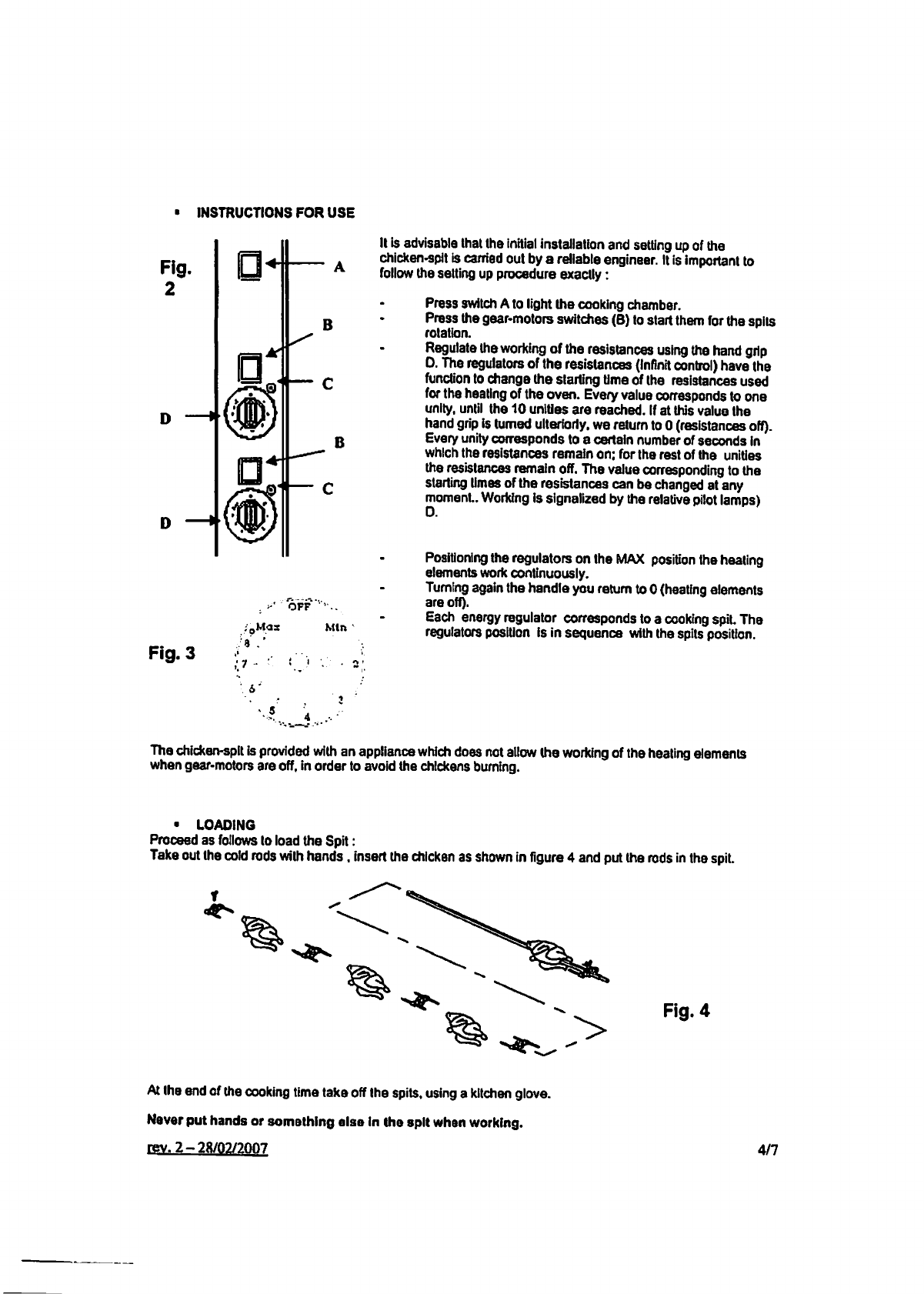
It
is
advisable
that
the
initial
Installation
and
setting
up
of
the
chicken-spit
is
carried
out
by
a
rdiable
engineer.
It
is
impoitant
to
follow
the
setting
up
procedure
exactly:
Press
switch
A
to
light
the
cooking
chamber.
Press
the
gear-motors
switches
(B)
to
start
them
for
the
spits
rotation.
Regulate
the
working
of
the
resistances
using
the
hand
grip
0.
The
regulators
of
the
resistances
(Infinit
control)
have
the
function
to
change
the
starting
time
of
the
resistances
used
for
the
heating
of
the
oven.
Every
value
corresponds
to
one
unity,
until
the
10
unlües
are
reached.
If
at
this
value
the
hand
grip
is
tumed
ulterioriy.
we
return
to
0
(resistances
off).
Every
unity
corresponds
to
a
certain
number
of
seconds
in
whlch
the
resistances
remain
on;
for
the
rest
of
the
unities
the
resistances
remain
off.
The
value
corresponding
to
the
starting
times
of
the
resistances
can
be
changed
at
any
moment..
Working
is
signalized
by
the
relative
pilot
lamps)
0.
Positioning
the
regulators
on
the
MAX
Position
the
heating
elements
work
continuously.
Tumlng
again
the
handle
you
return
to
0
(heating
elements
are
off).
Each
energy
regulator
corresponds
to
a
cooking
spit.
The
regulators
Position
is
in
sequence
with
the
spits
Position.
The
chicken-splt
is
provided
with
an
appliance
which
does
not
allow
the
working
of
the
heating
elements
when
gear-motors
are
off,
in
Order
to
avoid
the
chlckens
buming.
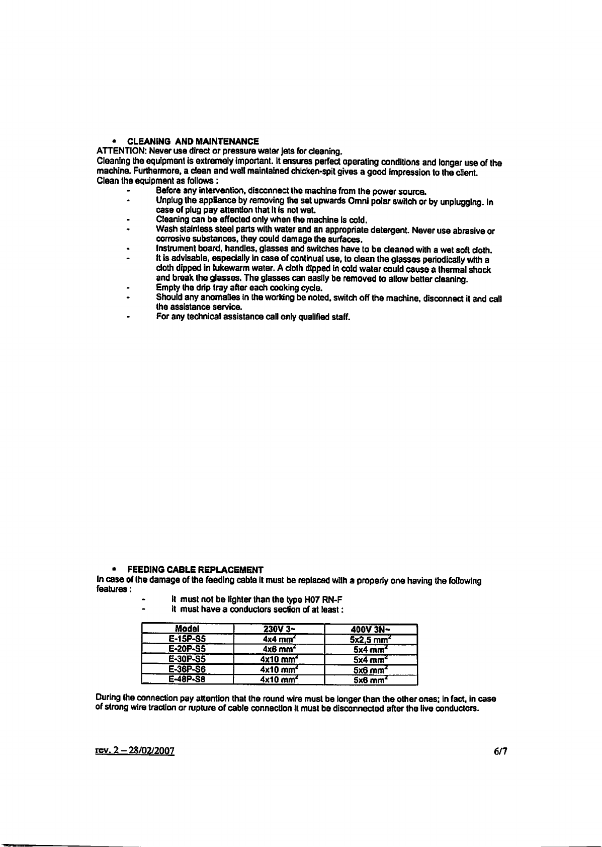
•
LOAOING
Proceed
as
follows
lo
load
the
Spit:
Take
out
the
cotd
rods
with
hands.
insert
the
chicken
as
shown
in
figure
4
and
put
the
rods
in
the
spit.
Fig.
4
At
the
end
of
the
cooking
time
take
off
Ihe
spits,
using
a
kitchen
glove.
Never
put
hands
or
somathing
alsa
in
Ihe
spll
when
working.
rev.
2-28/02/200,7
4/7

•
COOKING
TIMES
INDICATiVE
The
cooking
time
of
chlckens
of
approximately
depends
on
the
following
points:
preheating
of
the
chictcen-spit
meat
features
(lean
or
fal)
weight
and
form
of
the
product
Initial
temperature
of
the
product
to
be
cooked
and
the
desired
meat
brownlng.
The
particutar
configuraüon
of
the
cooking
chamber
of
these
new
modeis
of
chicken-spits
with
superposed
Single
spils
movement
allows
to:
obtain
the
cooking
of
the
chickens
placed
on
the
upper
spit
in
50/55
minutes
the
cooking
of
the
second
spit
will
end
withln
the
10/15
following
minutes
and
so
on
for
the
other
spits.
In
thls
way.
the
upper
spits
with
the
already
cooked
chlckens
can
be
replaced
with
other
spits
for
a
new
cooking.
•
USEINTRUCTIONS
To
obtain
better
results
foitow
these
instrudlons:
1.
Begin
the
loading
of
the
erticken
spit
starting
from
the
upper
spit
2.
Position
each
Single
energy
regulator
starting
from
pos.
8
until
the
MAX
Position
3.
If
you
want
to
make
a
partial
cooking
redudng
the
cooking
Urne
and
having
a
mlnor
cooking
surface
to
clean
it
is
possible
to
use
its
intermediate
fat
Container
(fig.
5)
Fig.
5
In
the
Internal
part
of
the
machlne
two
dilferent
positions
are
predisposed
for
the
intermediate
fat
Container:
in
the
upper
position
you
can
use
until
2
spits
in
the
second
position
(Iower)
you can
use
until
3
spits
rev.
2-28/02/2007
5/7
•
CLEANING
AND
MAINTENANCE
ATTENTION:
Never
use
dlrect
or
pressure
water
Jets
for
cleaning.
Cleaning
the
equipment
is
extremely
important.
It
ensures
perfect
operating
conditlons
and
longer
use
of
the
machine.
Furthermore,
a
dean
and
well
mainlained
chicken-spit
gives
a
good
impression
to
the
dient.
Clean
the
equipment
as
follows:
Before
any
intervention.
disconnect
the
machine
from
the
power
source.
Unplug
the
appliance
by
removing
the
set
upwards
Omni
polar
switch
or
by
unplugglng.
In
case
of
plug
pay
attention
that
it
is
not
wet.
Cleaning
can
be
effected
only
when
the
machine
is
cold.
Wash
stainless steel
parts
with
water
and an
appropriate
detergent
Never
use
abrasive
or
corrosive
substances,
they
could
damage
the
surfaces.
Instrument
board,
handles,
glasses
and
switches
have
to
be
deaned
with
a
wet
soft
clolh.
It
is
advisable,
espedally
in
case
of
continual
use.
to
clean
the
glasses
periodically
with
a
doth
dipped
in
lukewarm
water.
A
doth
dipped
in
cold
water
could
cause a
Ihermal
shock
and
break
the
glasses.
The
glasses
can
easily
be
removed
to
allow
better
cleaning.
Empty
(he
drip
tray
after
each
cooking
cycla.
Should
any
anomaties
in
the
working
be
noted,
switch
off
the
machine,
disconnect
it
and
call
(he
assistance
Service.
For
any
technical
assistance
call
only
qualified
staff.
■
FEEDING
CABLE
REPLACEMENT
In
case
of
Ihe
damage
of
the
feeding
cable
it
must
be
repiaced
with
a
properiy
orte
having
the
following
features:
It
must
not
be
lighter
than
(he
type
H07
RN-F
it
must
have
a
conductors
section
of at
least:
Model
E-15P-S5
E-20P-S5
E-30P-S5
E-36P-S6
E-48P-S8
230V
3-
4x4
mm'
4x6
mm'
4x10
mm'
4x10
mm'
4x10
mm'
400V
3N-
5x2.5
mm'
5x4
mm'
5x4
mm'
5x6
mm'
5x6
mm'
Ouring
the
connection
pay
attention
that
Ihe
round
wire
must
be
longer
than
the
other
ones;
in
fact,
in
case
of
Strang
wire
traction
or
rupture
of
cable
connection
It
must
be
disconnected
after
the
live
conductors.
rev.
2-28/02/2007
6/7

UGHT
REPLACEMENT
Unplug
the
appliance.
Remove
the
gtass
protection.
Unscrew
the
butb
and
replace
Ihe
light
with
a
new
one
having
the
same
features;
plug
the
protection
back
on.
•
ELECTRICAL
CONNECTION
See
enclosed
wiring
diagrams.
WARNING
Get
rid
of
the
machine
in
a
proper
way
following
the
national
disposal
rules.
Always
protect
the
machine
from
the
interventation
of
not
authorized
persons.
The
manufacturer
shall
not
be
held
responsible
If
the
Instructions
contained
in
the
booklet
are
not
followed.
rev.
2
-28/02/2007
7/7
This manual suits for next models
4
Table of contents
Other Neumaerker Grill manuals


Popular Grill manuals by other brands


Uniflame
Uniflame GBT1111W-C owner's manual

Black & Decker
Black & Decker SizzleLean IG100 Series Use and care book

Ducane
Ducane Affinity S 3200 owner's manual

Vermont Castings
Vermont Castings VANGUARD G54005 Assembly manual

Philips
Philips HD6372 user manual

George Foreman
George Foreman Slide-Temp GR120V Use and care book


