Neumann.Berlin N 248 User manual

neumann.berlin
the microphone company
georg neumann gmbh · ollenhauerstr. 98 · 13403 berlin · germany
Bedienungsanleitung
Operating Instructions
N 248

2 3
N 248
Table of Contents
1. N 248 Phantom Power Supply
2. Operation with Remote Controllable Directional
Characteristics
3. Con entional Operation
4. Plug Connectors and Connecting Cables
5. Opening the Case
6. Plug-In Mains Unit/External Power Supply
7. Technical Specifications
1. N 248 Phantom Power Supply
The N 248 phantom power supply pro ides pow-
er for two phantom-powered microphones accord-
ing to DIN EN 61938/IEC 1938. Alternati ely to
the standard P48 mode of operation, it is possible
to remote control of the microphone directional
characteristic, pro ided this mode of operation is
also supported by the microphone.
Inhaltsverzei hnis
1. Das Netzgerät N 248
2. Betrieb mit fernsteuerbaren
Richtcharakteristiken
3. Kon entioneller Betrieb
4. Steck erbinder und Anschlusskabel
5. Öffnen des Geräts
6. Steckernetzteil/externe Strom ersorgung
7. Technische Daten
1. Das Netzgerät N 248
Das Netzgerät N 248 dient der Strom ersorgung
zweier phantomgespeister Mikrophone nach DIN
EN 61938/IEC 1938. Alternati zur Standardbe-
triebsart P48 kann eine Betriebsart zur Fernum-
schaltung der Mikrophon-Richtcharakteristik ge-
wählt werden, sofern diese Betriebsart auch mikro-
phonseitig unterstützt wird.
N 248 EU
mit Ste kernetzteil EU
230 V, 50 Hz ......................... Best.-Nr. 08537
N 248 US
mit Ste kernetzteil US
117 V, 60 Hz ......................... Best.-Nr. 08538
N 248 UK
mit Ste kernetzteil UK
230 V, 50 Hz ......................... Best.-Nr. 08539
Die Leistungsaufnahme des Netzgeräts beträgt
maximal 3 VA.
2. Betrieb mit fernsteuerbaren
Ri ht harakteristiken
Die Steuerung fernumschaltbarer Mikrophone, wie
z.B. des TLM 127 oder TLM 170 R, wird mittels
Drehschalter an der Frontplatte des N 248 orge-
nommen. Es gibt 6 Schalterstellungen: 5 Richt-
charakteristiken in der Fernsteuerbetriebsart und
eine Stellung für die herkömmliche Betriebswei-
se P48. Im Falle der Fernsteuerbetriebsart ist es
erforderlich, dass der Richtcharakteristikschalter
am angeschlossenen Mikrophon in Stellung „R“
(Remote) gebracht wird.
Die Fernsteuerung basiert technisch auf einem
on Neumann entwickelten und patentierten Ver-
fahren, bei dem die Phantomspannung innerhalb
der in der Norm erlaubten Toleranzen geregelt
wird, so dass die auf die Tonadern eingekoppelte
Spannung einen definierten Betrag einnimmt. Das
Mikrophon wertet die absolute Höhe der Tonader-
spannung aus und stellt seine Richtcharakteristik
entsprechend ein. Die Variation der Phantomspan-
nung erfolgt derart, dass eine Tonaderspannung
on 37...43 V in 1,5 V-Schritten erzeugt wird. Wei-
tere Hinweise sind der Bedienungsanleitung des
jeweiligen Mikrophons zu entnehmen.
Anmerkung: Anmerkung:
Anmerkung: Anmerkung:
Anmerkung: Das Umschalten der Richtcharakte-
ristik wird durch elektrisches Umladen einer Kap-
selhälfte erreicht. Dies kann mit starken Störge-
räuschen erbunden sein, weil die Ladespannun-
gen um ein Vielfaches größer als typische
Audiosignale sind. Es wird deshalb empfohlen,
beim Umschalten der Richtcharakteristik die Ver-
stärkung des Mikrophonsignals zurückzunehmen.
N 248 EU
with plug-in mains unit EU
230 V, 50 Hz .......................... Part No. 08537
N 248 US
with plug-in mains unit US
117 V, 60 Hz .......................... Part No. 08538
N 248 UK
with plug-in mains unit UK
230 V, 50 Hz .......................... Part No. 08539
The maximum power consumption of the power
unit is 3 VA.
2. Operation with Remote Controllable
Dire tional Chara teristi s
Remote controllable microphones, such as the
TLM 127 or TLM 170 R, are controlled using a ro-
tary switch on the front panel of the N 248. There
are six switch positions: fi e are directional char-
acteristics in the remote control mode of operation
and one is a setting for the standard P48 mode of
operation. When the remote control mode of oper-
ation is used, the directional characteristic switch
on the connected microphone must be set to “R”
(Remote).
The remote control is based on a technology de-
eloped and patented by Neumann in which the
phantom supply oltage is regulated within the
tolerances permitted in the standard in such a
manner that the oltage coupled into the signal
conductors takes on a defined alue. The micro-
phone e aluates this alue of signal conductor
oltage and adjusts its directional characteristic
accordingly. The ariation on phantom oltage at
the signal conductor is 37…43 V with 1.5 V incre-
ments. For additional information, see the operat-
ing instructions accompanying the respecti e mi-
crophone.
Note: Note:
Note: Note:
Note: The polar pattern is changed by electrical-
ly recharging one side of the capsule. This may in-
duce a sharp noise as the polarization oltages
are much larger than typical audio signals. It is
therefore recommended to reduce the console gain
setting when switching the polar pattern.
Eine Leuchtdiode auf der Frontplatte zeigt Be-
triebsbereitschaft an.
Das N 248 wird in drei Varianten angeboten, die
sich nur im mitgelieferten Steckernetzteil unter-
scheiden:
Readiness for operation is indicated by an LED on
the front panel.
The N 248 is offered in three ariants that differ
only in the plug-in mains unit included:
4 5
N 248
3. Conventional Operation
For microphones that are not remote-controllable,
or that ha e not been set to “R” (Remote), it is rec-
ommended to set the corresponding rotary switch
on the N 248 to the P48 position. Remote-control-
lable microphones that are set to “R” (Remote), on
the other hand, should ne er be operated in the
“P48” position, since this would result in random,
uncontrolled changing of the directional charac-
teristic.
The two channels of the N 248 can be controlled
separately. Thus it is possible to operate remote-
controllable and con entional microphones in
parallel.
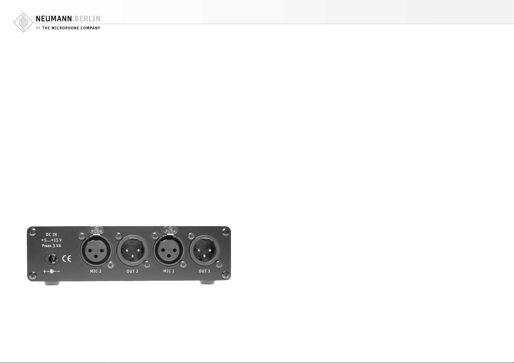
4. Plug Conne tors and Conne ting Cables
The N 248 power supply is pro ided with two
XLR 3 F inputs and two XLR 3 M outputs.
The outputs of the N 248 are dc-free and protect-
ed against damage if another, external phantom
supply is connected to the output. In order for the
remote control to function properly, it is essential
that any external phantom supply oltage con-
nected be switched off.
The lower limit frequency of the decoupling circuit
is below 5 Hz, with an output load of at least
600 ohms.
3. Konventioneller Betrieb
Für Mikrophone, die nicht fernumschaltbar sind
oder deren Richtcharakteristikschalter sich nicht
in Stellung „R“ (Remote) befindet, wird empfoh-
len, den entsprechenden Drehschalter am N 248 in
Stellung P48 zu bringen. Fernumschaltbare Mikro-
phone, die sich in Stellung „R“ (Remote) befinden,
sollten hingegen auf keinen Fall in „P48“-Stel-
lung betrieben werden, da in diesem Fall eine zu-
fällige und unkontrollierte Richtcharakteristik
entsteht.
Die beiden Kanäle des N 248 sind getrennt steu-
erbar. Daher ist es möglich, fernumschaltbare und
kon entionelle Mikrophone parallel zu betreiben.
4. Ste kverbinder und Ans hlusskabel
Das Netzgerät N 248 besitzt zwei 3-polige XLR-
Eingänge und zwei 3-polige XLR-Ausgänge.
Die Ausgänge des N 248 sind gleichstromfrei und
gegen das Anlegen einer externen Phantomspei-
sung geschützt. Für die korrekte Funktion der
Fernsteuerung ist es unbedingt nötig, eine e en-
tuell anliegende externe Phantomspeisung abzu-
schalten.
Die untere Grenzfrequenz der Auskoppelschaltung
liegt bei einer Ausgangslast on mindestens
600 Ohm unter 5 Hz.
Für den Anschluss an unsymmetrische Geräte oder
Geräte mit XLR 5-Verbindern dienen die folgenden
Adapterkabel:
AC 20 (1 m) .......................... Best.-Nr. 06595
Y-Kabel mit einer 5-poligen XLR-Buchse und zwei
3-poligen XLR-Steckern, für die Verteilung on
2-kanaliger Modulation auf 2 Monokanäle.
AC 25 (0,3 m) ...................... Best.-Nr. 06600
Adapterkabel mit XLR 3 F-Buchse und 6,3 mm Mo-
noklinkenstecker, unsymmetrisch, für den An-
schluss des 3-poligen XLR-Ausganges eines Spei-
segerätes an Geräte mit 6,3 mm Monoklinken-
buchse. Für alle Mikrophone mit Ausnahme der
Ausgangsstufe KM 100 und des GFM 132.
AC 26 (0,3 m) ...................... Best.-Nr. 06601
Adapterkabel mit XLR 3 F-Buchse und 6,3 mm Mo-
noklinkenstecker, unsymmetrisch, für den An-
schluss des XLR 3 F-Ausganges eines Speisegerä-
tes an Geräte mit 6,3 mm Monoklinkenbuchse. Vor-
gesehen nur für die Ausgangsstufe KM 100 und
das GFM 132.
5. Öffnen des Geräts
Das Netzgerät darf nur in spannungsfreiem Zustand
geöffnet werden. Vor dem Öffnen des Netzgeräts
sind die Bedienknöpfe on den Schalterachsen
abzuziehen. Dann werden die ier Kreuzschlitz-
schrauben auf der Rückseite herausgeschraubt.
Anschließend lässt sich der gesamte Innenaufbau
herausziehen.
Der Zusammenbau erfolgt in umgekehrter Reihen-
folge. Beim Aufsetzen der Bedienknöpfe ist auf
deren Ausrichtung bezüglich der Schalterposition
zu achten.
For connection to unbalanced inputs, or de ices
with XLR 5 connectors the following cables are
a ailable:
AC 20 (1 m) ............................ Cat. No. 06595
Y-cable with one XLR 5 F connector and two
XLR 3 M connectors. It is used to split two-chan-
nel signals into two mono channels.
AC 25 (0.3 m) ......................... Cat. No. 06600
Adapter cable with XLR 3 M connector and unbal-
anced 6.3 mm mono jack. It is used to connect 3-
pin XLR outputs of power supplies to units with a
6.3 mm monojack input. Designed for all micro-
phones, excluding KM 100 System and GFM 132.
AC 26 (0.3 m) ......................... Cat. No. 06601
Adapter cable with XLR 3 M connector and unbal-
anced 6.3 mm mono jack. It is used to connect
XLR 3 outputs of power supplies to units with a
6.3 mm monojack input. Designed only for KM 100
System and GFM 132.
5. Opening the Case
The case may only be opened when it is not con-
nected to oltage. Remo e the control knobs from
the switch axes, then the four Philips screws on the
back. The entire inner assembly can then be pulled
out.
Reassembly takes place in re erse order. When re-
attaching the control knobs, attention should be
paid to how they are orientated in relation to the
switch position.

6 7
N 248
6. Separates Netzgerät/
externe Stromversorgung
Die Speisung des N 248 erfolgt im Normalfall über
das mitgelieferte Steckernetzteil. Alternati kann
auch ein anderes handelsübliches Steckernetzteil
mit einer Spannung zwischen +5...+15 V ( orzugs-
weise geregelt) erwendet werden; die abgege-
bene Leistung muss mindestens 3 VA betragen,
auf richtige Polung des Steckers ist zu achten.
Ersatzteilnummern Steckernetzteil:
NT 2 EU ................................ Best.-Nr. 77687
NT 2 UK ................................ Best.-Nr. 77688
NT 2 US ................................ Best.-Nr. 77689
7. Te hnis he Daten
Für alle Versionen:
Leistungsaufnahme ............................. max. 3 VA
Eingangsspannung ............................ +5...+15 V
Ausgangsspannung (auf den Tonade n)
Bet iebsa t P48 ..................... abhängig von de
St omaufnahme des Mik ophons,
inte ne Einspeisung (+48 VDC)
gemäß Standa d
DIN EN 61938/IEC 1938
Bet iebsa t REMOTE ................. +37...+43 VDC,
abhängig von Schalte position
bzw. de gewünschten
Richtcha akte istik
Ausgangsst om
Bet iebsa t P48 .......................... max. 2 x 6 mA
Bet iebsa t REMOTE .................... max. 2 x 4 mA
Eigenstö pegel ............... –132 dBu (0,2 µVeff)
(Mik ophonausgangsimpedanz
200 Ohm, f=20 Hz...20 kHz)
Bet iebsspannungsunte d ückung ............ >80 dB
(bezogen auf DC-Eingang,
Mik ophonausgangsimpedanz
200 Ohm, f 50 Hz)
Abmessungen (B x H x T) ....... 143 x 38 x 103 mm
Gewicht (ohne Stecke netzteil) .................. 415 g
6. Separate Plug-In Mains Unit/
External Power Supply
The N 248 is normally powered by the plug-in
mains unit included. Alternati ely, it is possible
to use another ordinary plug-in mains unit with a
oltage of +5 to +15 V (preferably regulated); the
unit must deli er at least 3 VA. Take care that the
plug has the correct polarity.
Plug-in mains unit replacement part numbers:
NT 2 EU ................................. Part No. 77687
NT 2 UK ................................. Part No. 77688
NT 2 US ................................. Part No. 77689
7. Te hni al Data
For all versions:
Powe consumption .............................. max. 3 VA
Input voltage ..................................... +5...+15 V
Output voltage (on the signal conducto s)
P48 mode .............................. depending on the
powe consumption of the mic ophone,
phantom supply voltage (+48 VDC)
acco ding to standa d
DIN EN 61938/IEC 1938
REMOTE mode ......................... +37...+43 VDC,
depending on switch position
and/o the desi ed
di ectional cha acte istic
Output cu ent
P48 mode ................................... max. 2 x 6 mA
REMOTE mode ............................ max. 2 x 4 mA
Self-noise level .............. –132 dBu (0.2 µVeff)
(Mic ophone output impedance
200 Ohm, f=20 Hz...20 kHz)
Supply voltage supp ession ..................... >80 dB
( elative to DC input,
Mic ophone output impedance
200 Ohm, f 50 Hz)
Dimensions (W x H x D) ......... 143 x 38 x 103 mm
Weight (without plug-in mains unit) ........... 415 g
AC 20 AC 25 AC 26

Irrtümer und technische Änderungen vorbehalten • Errors excepted, subject to changes
Printed in Germany • Publ. 7/ 4 93813
Table of contents
Other Neumann.Berlin Power Supply manuals


