Neumann.Berlin KH 420 User manual
· . · ·
()/ - · - · @. · ..
KH
A S M
O M


KH 420 | 1
Important safety instructions ...............................................2
The KH 420 studio monitor..................................................4
Package contents ..........................................................4
Product overview ..........................................................5
Installing and connecting the KH 420 ........................................8
Preparing the loudspeakers ............................................8
Preparing the room...................................................10
Positioning the loudspeaker ...........................................10
Connecting audio signals..............................................13
Connecting/disconnecting the KH 420 to/from the mains power supply......16
Configuring and using the KH 420 .......................................... 17
Switching the KH 420 on/o ...........................................17
Adjusting the frequency response ......................................17
Adjusting the acoustical level..........................................19
Compensating for video delay (lip sync) ................................20
Compensating for listening distance dierences (time-of-flight) ............20
Activating ground lift .................................................21
Adjusting the brightness of the Neumann logo ...........................22
Cleaning and maintaining the KH 420 .......................................22
Troubleshooting ..........................................................22
Specifications ............................................................23
Accessories ..............................................................25
Manufacturer Declarations .................................................26
Contents
Appendix
System Block Diagram ............................................I
Pin assignment of the XLR socket....................................I
Acoustical Measurements..........................................I
Installation angles ..............................................XI
Delay Lookup Table ............................................XII
EN

2| KH 420
Important safety instructions
1. Read these instructions.
2. Keep these instructions. Always include these instructions when passing the product on
to third parties.
3. Heed all warnings.
4. Follow all instructions.
5. Do not use this apparatus near water.
6. Only clean the product when it is not connected to the mains power supply. Clean only
with a dry cloth.
7. Always ensure a free air flow around the cooling fins on the rear of the product. Do not
block any ventilation openings. Install in accordance with the manufacturer’s instructions.
8. Do not install near any heat sources such as radiators, heat registers, stoves, or other
apparatus (including amplifiers) that produce heat.
9. Do not defeat the safety purpose of the polarized or grounding-type plug. A polarized plug
has two blades with one wider than the other. A grounding type plug has two blades and
a third grounding prong. The wide blade or the third prong are provided for your safety.
If the provided plug does not fit into your outlet, consult an electrician for replacement of
the obsolete outlet.
10. Protect the power cord from being walked on or pinched, particularly at plugs, conveni-
ence receptacles, and the point where it exits from the apparatus.
11. Only use attachments/accessories specified by the manufacturer.
12. Use only with the cart, stand, tripod, bracket, or table specified by the manu-
facturer, or sold with the apparatus. When a cart is used, use caution when
moving the cart/apparatus combination to avoid injury from tip-over.
13. Unplug this apparatus during lightning storms or when unused for long periods of time.
14. Refer all servicing to qualified service personnel. Servicing is required when the appara-
tus has been damaged in any way, such as power supply cord or plug is damaged, liquid
has been spilled or objects have fallen into the apparatus, when the apparatus has been
exposed to rain or moisture, does not operate normally, or has been dropped.
15. To completely disconnect this apparatus from the AC mains, disconnect the power supply
cord plug from the AC receptacle.
16. WARNING: To reduce the risk of fire or electric shock, do not expose this apparatus to rain
or moisture.
17. Do not expose this equipment to dripping or splashing and ensure that no objects filled
with liquids, such as vases, are placed on the equipment.
18. The mains plug of the power supply cord shall remain readily accessible.
• Ensure that the room in which you use this product is wired in accordance with the local
electrical code and checked by a qualified inspector.
• Only use the product indoors.
• Do not install the product in hot, humid, or excessively dusty locations, in direct sunlight or
in locations where it is exposed to externally generated vibrations.
• Do not place burning objects (e.g. candles) on top of or near the product.
• If condensation has formed on the product, e.g. because it was moved from a cold environ-
ment to a warm one, allow the product to acclimatize to room temperature before using it.
• Do not overload wall outlets and extension cables as this may result in fire and electric
shock.
Installation
EN

KH 420 | 3
WARNING
Danger of hearing damage due to sudden high sound pressure levels!
Audio signals that are present at switch-on of the product or that can be present during
operation, can create sudden, very high sound pressure levels which can damage your hea-
ring.
XAlways lower the output level of the audio source before connecting it to the loudspeaker
or starting it (pressing “play”).
If the DIM1 accessory has been fitted:
XAlways lower the output level of the audio source before switching to a dierent
source (analog/digital) via the SIGNAL SELECT rotary switch Lof the DIM1
accessory.
DIM 1
DIM 1
DIM 1
1
1
1
1
1
1
1
1
1
1
1
1
1
1
1
1
1
1
1
1
1
1
1
1
1
M
M
M
M
M
M
M
M
M
M
M
M
M
M
M
M
M
M
M
M
M
M
M
M
M
M
M
M
M
M
I
I
I
I
I
I
I
I
I
II
I
II
I
I
I
I
D
D
D
D
D
D
D
D
D
D
D
D
D
D
D
D
D
D
D
D
D
D
D
D
D
D
D
This loudspeaker can be used for commercial purposes. Commercial use is subject to the rules
and regulations of the trade association responsible. Neumann, as the manufacturer, is there-
fore obliged to expressly point out possible health risks arising from use. This loudspeaker is
capable of producing sound pressure levels exceeding 85dB(A) SPL. This is the sound pres-
sure corresponding to the maximum permissible level which is by law (in some countries)
allowed to aect your hearing for the duration of a working day (8 hours). It is used as a basis
according to the specifications of industrial medicine. Higher sound pressure levels and/or
longer durations can damage your hearing. At higher sound pressure levels, the duration must
be shortened in order to prevent hearing damage. The following are signs that you have been
subjected to excessive sound pressure levels for too long a time:
• You can hear ringing or whistling sounds in your ears.
• You have the impression (even for a short time only) that you can no longer hear high fre-
quencies (temporary threshold shift).
WARNING
Interference due to magnetic fields!
This product generates a permanent magnetic field (> 1.5 mT) that can interfere with car-
diac pacemakers and implanted defibrillators (ICDs).
XAlways maintain a distance of at least 10 cm (4") between the loudspeaker and the car-
diac pacemaker or implanted defibrillator.
The label shown on the right is attached to the rear of the
product.
The symbols on this label have the following meaning:
Presence of uninsulated dangerous voltage within the product’s enclo-
sure that may be of sucient magnitude to constitute a risk of fire or
electric shock.
Never open the product or remove the grilles fitted to the product as
there is a risk of electric shock. There are no user serviceable parts
inside. Refer servicing to your Neumann service partner.
Read and follow the safety and operating instructions contained in the
operating manual.
Intended use of the product includes:
• having read this operating manual, especially the chapter “Important safety instructions”,
• using the product within the operating conditions and limitations described in this opera-
ting manual.
“Improper use” means using the product other than as described in this operating manual, or
under operating conditions which dier from those described herein.
Danger due to
high sound
pressure levels
Magnetic fields
Hazard warnings
on the rear of
the product
Intended use
EN

4| KH 420
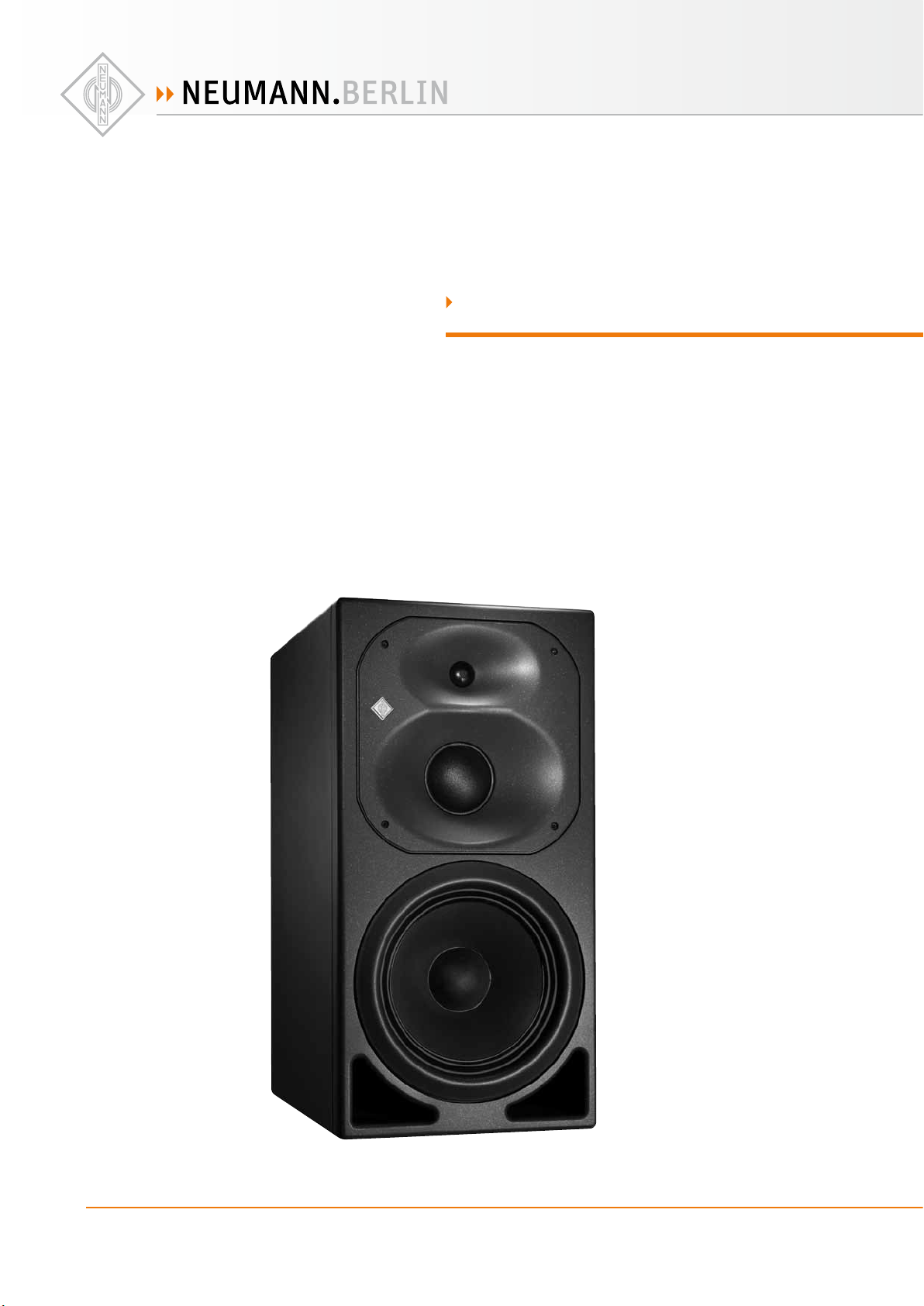
The KH 420 studio monitor
Thank you for purchasing a Neumann studio monitor. The KH 420 features a Mathematically
Modeled Dispersion™ Waveguide (MMD™), flexible acoustical controls, various input options
and an extensive range of mounting hardware. This allows the loudspeaker to be used in
diverse acoustical conditions, with any source equipment and in a wide variety of physical
locations. The KH 420 represents the latest in acoustic and electronic simulation and measure-
ment technologies to ensure the most accurate sound reproduction possible.
The KH420 is designed for use as mid-field and main monitor. It can be used as a front louds-
peaker in mid-sized and large multi-channel systems, or as a rear loudspeaker in larger multi-
channel systems.
Package contents
1 KH 420
3 Mains cables (European, UK and US versions)
1 Operating manual
1 “Getting Started Quickly” supplement
Note that imperial dimensions are approximate.
The current operating manual as well as the supplement “Getting Started Quickly” can also be
downloaded from the “Downloads” area on the product page at www.neumann.com.
EN
KH 420 | 5
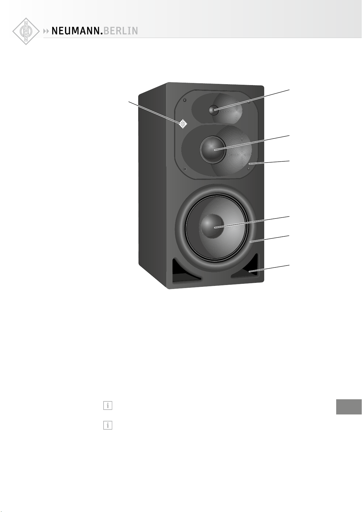
Product overview
2
4
1
3
5
6
7
1Neumann logo
•lights up white:
loudspeaker is switched on and ready for operation
•flashes red:
loudspeaker’s protection system is active
output level is reduced
or, if the optional DIM1 accessory is installed:
A digital signal is selected via the SIGNAL SELECT rotary
switch Lbut there is no valid digital signal connected
•lights up red:
electronic’s temperature is too high
output level is reduced by 20dB
or
input signal is constantly high
output level is slightly reduced
2Treble driver
3Midrange driver
4Rotatable waveguide
5Bass driver
6Woofer ring*
7Bass reflex ports
You can adjust the brightness of the Neumann logo. For more information, refer to
page22.
When installing a Remote Electronics Kit (REK4) the electronics panel and the cabi-
net that were originally shipped together should be connected together, otherwise the
anechoic calibration is lost. To help with this during installation, the serial number
shown on the electronics panel is also printed behind the woofer ring 6. To remove the
woofer ring, carefully place your fingers on either side of the inside of the woofer ring,
press outwards, and then pull towards you. To refit the woofer ring, align the pegs with
the holes and gently push until the woofer ring is fully inserted.
EN
6| KH 420
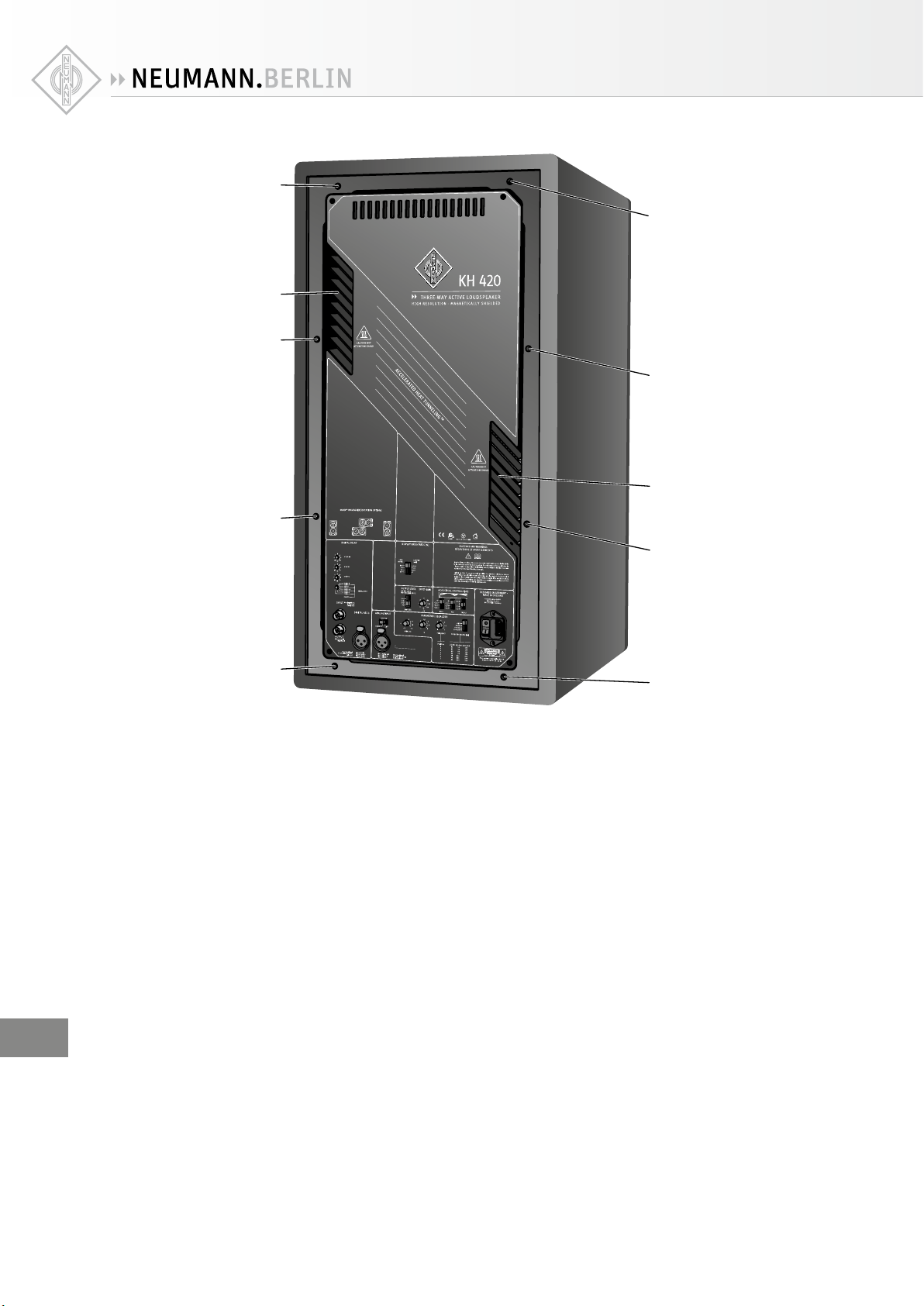
9
8
8
8
8
8
8
9
8
8
8Threaded inserts for mounting hardware
Remove inserted plastic plugs before attaching mounting hardware.
9Accelerated Heat Tunneling™ cooling fins (AHT™)
EN
KH 420 | 7
Pin 1: Audio GND
Pin 2: Signal +
Pin 3: Signal -
ANALOG INPUT
GROUND
CONNECT
PARAMETRIC EQUALIZER
GAIN [dB] Q
TREBLEMIDBASS
ACOUSTICAL CONTROLS [dB]
25-80
50-160
100-320
OFF
OUTPUT LEVELINPUT GAIN
for 0 dBu
DISPLAY BRIGHTNESS [%]
100
60
30
OFF
OUTPUT
SIGNAL SELECT
DIGITAL DELAY
x 1.6 ms
x 25.6 ms
x 0.1 ms
DIGITAL AES 3
Max. input level
1.2 V pk-pk
unbalanced
INPUT
ANALOG
ANALOG *
DIGITALA+B
DIGITALA+B
DIGITAL A
DIGITAL A
DIGITAL B
DIGITAL B
DELAYED 114
94
100
108
LIFT
100
60
30
LOGO
(white)
LIMITER
(red)
Pin 1: Shield
Pin 2: Signal +
Pin 3: Signal -
Sleeve: Shield
Tip: Signal
-12
-5
-2
0
+1
+2
+4
1
1.5
22.5 3
4
81
2
345
6
7
FREQUENCY FREQUENCY RANGE [Hz]
Position
25
32
40
45
52
65
80
25-80
50
64
80
90
105
130
160
50-160
100
130
160
180
210
260
320
100-320
1
2
3
4
5
6
7
-12
-4
-14
-10
-6
-2
[dB SPL at 1 m
for 0 dBu / -18 dB FS]
-1.0
-2.0
+1.0
-1.5
-3.0
-4.5
-2.5
-7.5
-5.0
0
00
Max. input level
7 V pk-pk transformer
balanced
Max. input level
24 dBu (*18 dBu for
analog delayed)
-8
0
IF
C
AB
KHGD
E
MLJ
DIM 1
DIM 1
DIM 1
D
D
D
DD
D
D
D
D
D
D
D
D
D
D
D
D
D
D
D
D
D
D
D
D
D
1
1
1
1
1
1
1
1
1
1
1
1
1
1
1
1
1
1
1
M
M
M
M
M
M
M
M
M
M
M
M
M
M
M
M
M
M
M
M
M
M
M
I
I
I
I
I
I
I
I
I
I
I
I
I
0DISPLAY BRIGHTNESS switch
(Dims the Neumann logo)
AOUTPUT LEVEL switch
BINPUT GAIN control
CACOUSTICAL CONTROLS switches
DIEC mains socket
EOn/o switch I/0
FPARAMETRIC EQUALIZER controls
• PARAMETRIC EQUALIZER | GAIN [dB]
• PARAMETRIC EQUALIZER | Q
• PARAMETRIC EQUALIZER | FREQUENCY [Hz]
• PARAMETRIC EQUALIZER|FREQUENCY RANGE [Hz]
GGROUND switch
(Connects/disconnects ground)
HANALOG INPUT socket (XLR)
IAES3 INPUT socket (XLR)
JAES3 INPUT socket (BNC)
KAES3 OUTPUT socket (BNC)
LSIGNAL SELECT rotary switch
MDELAY rotary switches
DIM 1
DIM 1
DIM 1
1
1
1
1
1
1
1
1
1
1
1
1
1
1
1
1
1
1
1
1
1
1
1
1
1
M
M
M
M
M
M
M
M
M
M
M
M
M
M
M
M
M
M
M
M
M
M
M
M
M
M
M
M
M
M
I
I
I
I
I
I
I
I
III
I
II
I
I
I
I
D
D
D
D
D
D
D
D
D
D
D
D
D
D
D
D
D
D
D
D
D
D
D
D
D
D
D
DIM1 is an optional accessory not included in
the package contents of the KH420. If the DIM1
is not installed, the backplate‘s area marked
with DIM1 in the drawing above will be covered
with a sticker.
Always have the DIM1 installed by an autho-
rized Neumann service partner.
EN

8| KH 420
Installing and connecting the KH 420
CAUTION
Danger of injury and material damage due to tipping/dropping of the product!
If improperly mounted, the product and/or the mounting hardware (e.g. rack) can tip over
or drop down.
XAlways have the product mounted by a qualified specialist according to local, national
and international regulations and standards.
XUse the mounting systems recommended by Neumann and always provide sucient
additional protection against tipping or dropping!
CAUTION
Damage to the product due to overheating!
If air cannot circulate properly around the cooling fins on the rear of the product, the
amplifier(s) may overheat leading to premature activation of the thermal protection system
which limits the maximum output level of the loudspeaker. In rare cases, damage to the
product may also occur.
XNever cover the entrance and exit slots for the Accelerate Heat Tunneling™ cooling fins.
XRegularly clean the Accelerate Heat Tunneling™ cooling fins.
XWhen installing the product into tight spaces such as wall recesses, maintain an air gap
of at least 5 cm (2") around the rear of the product and provide sucient air circulation.
If necessary, use forced-air cooling (e.g. when flush mounted in a wall), or use a REK4
(remote electronics kit).
It is possible to remove the electronics panel and locate it remotely, using the REK4
accessory and Cable Packs, CP nn.
For information on installation, please refer to the supplied “Getting Started Quickly”
supplement. This will help you set up the loudspeakers in a way that will give you the
best acoustic performance from the system.
For further information on setting up loudspeakers, please refer to the “Questions &
Answers” section on the product page at www.neumann.com.
For more information on building systems using Neumann loudspeaker products, please
refer to the “Product Selection Guide” at www.neumann.com
Preparing the loudspeakers
CAUTION
Risk of staining surfaces!
Some surfaces treated with varnish, polish or synthetics may suer from stains when they
come into contact with other synthetics. Despite a thorough testing of the synthetics used
by us, we cannot rule out the possibility of staining.
XDo not place the KH420 on delicate surfaces.
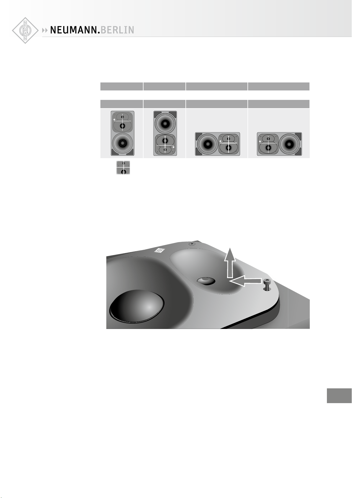
The MMD™ waveguide of the KH420 is rotatable. Rotating the MMD™ waveguide allows you
to place the bass driver either side of it. If the cabinet is positioned upside down, the MMD™
should also be upside down to maintain an optimum response in the bass-midrange crossover
region. In all cabinet orientations, the acoustical axis should point towards the engineer’s
listening position, or the center of the listening area, in both the horizontal and vertical planes
– see the definition of the acoustical axis.
Rotating the
MMD™ waveguide
EN
KH 420 | 9
See the table below for rotation angles of the MMD™ waveguide depending on the mounting
direction.
If you rotate your cabinet by …
0° 180° 90° clockwise 90° anticlockwise
Your MMD™ waveguide should be rotated within the cabinet by …
0° 0° 90° anticlockwise 90° clockwise
= Acoustical center
To rotate the MMD™, proceed as follows:
XLay the loudspeaker cabinet on its back on a soft flat surface so the drivers are facing
upwards. Ensure that none of the control knobs and switches on the back panel can be
damaged by the surface.
XUndo the four bolts on the MMD™ waveguide using a T25 Torx head screwdriver.
XCarefully lift the MMD™ waveguide out of the cabinet avoiding scratches on the paintwork
and damage to the sealing strip (pressing the screw to one side, as shown below, and pulling
up can make this task easier):
XRotate the MMD™ waveguide to the new orientation (see table above) and position it back
into the front panel cut-out. To avoid rattles, the driver cables are tightly sandwiched bet-
ween the rear of the waveguide and the damping material.
XEnsure that the driver cables do not touch the edges of the cabinet.
XTighten the four bolts on the MMD™ waveguide to a torque setting of 2 Nm (1.48 lbf-ft).
XTest the cabinet sealing by playing a reasonably loud (so you can feel some wind through
the ports) 32Hz sine wave. Then listen for any hissing sounds around the edge of the MMD™
waveguide and its drivers. If there is a hissing sound, the sealing has been compromised
and should be repaired.
Once the waveguide has been rotated the logo will be incorrectly oriented:
XCarefully lever the logo out using a sharp knife.
XReinsert the logo the correct way round.
The benefits of flush mounting are reduced cabinet edge diraction (smoother midrange),
increased bass driver loading (reduced bass distortion), and elimination of rear wall cancella-
tions (flatter bass response).
Flush mounting
the KH420
EN

10 | KH 420
A Remote Electronics Kit is highly recommended to avoid heat dissipation problems and
allow easy adjustment of the controls.
XHave the flush mounting designed by an experienced acoustic engineer. The following inst-
ructions are addressed to this experienced acoustic engineer.
XDesign the flush mounting wall‘s construction angles such that the loudspeaker’s acoustical
axis directly points horizontally and vertically towards the listening position or the centre
of the listening area.
XAcoustically isolate the cabinet from the wall. This avoids transmission of vibrations to the
flush wall.
To avoid midrange coloration:
XDo not put a “picture frame” around the edge of the cabinet that sticks out from the wall and
front panel. Also avoid any other acoustical discontinuities near the cabinet.
XCompensate the acoustical loading using the recommended acoustical control settings
shown in the “Adjusting the frequency response” section on page 17. A heavier wall
provides more loading which should be compensated with more “bass” attenuation.
If the loudspeaker must be covered:
XUse a thin open weave cloth. Two layers of very thin material will improve opacity.
Preparing the room
XArrange the loudspeaker setup symmetrically in the listening room.
XArrange all acoustically relevant surfaces and objects symmetrically on either side of the
listening axis of the room (left/right).
XMinimize the sound that is reflected back to the listening position by using angled surfaces
and/or acoustical treatment.
This product has been optimized for use in recording studios. In order to not aect the
quality of reproduction, make sure that the product is used in an EMC (electromagneti-
cally compatible) environment.
Positioning the loudspeaker
XCarry out the following steps very accurately, since the more accurate the physical arran-
gement of the loudspeakers in the room, the more accurate the reproduction will be at the
listening position.
XObserve the recommended distances between the loudspeakers and your listening position
(imperial dimensions are approximate):
• Minimum: 1.25 m (4')
• Recommended: 1.5–3.0 m (5'–9')
• Maximum: 11.0 m (33')
XAvoid positioning the loudspeaker at a distance “dwall” of 0.8 to 2 m (2' 6" to 6') from the
wall behind the loudspeaker.
When positioning bass managed loudspeakers:
XAvoid a distance “dwall” of 0.8 to 1 m (2' 6" to 3') from a solid wall behind the loudspeaker.
Similarly, avoid these distances from solid side walls or a solid ceiling. Respecting these
positioning limitations reduces the chances of dips and peaks in the low frequency res-
ponse (comb filtering) caused by strong reflections.
Distances
EN
KH 420 | 11
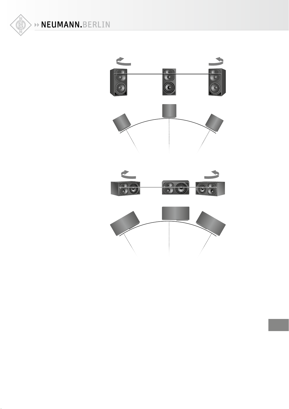
When positioning vertically oriented cabinets:
+30°-30°
+30°
-30° 0°
Front Left Front Center Front Right
When positioning horizontally oriented cabinets:
+30°-30°
+30°
-30° 0°
Front Left Front Center Front Right
XCopy the diagram “Installation angles” that can be found at the end of this operating
manual.
XPlace the diagram at the listening position or center of the listening area.
XUsing a tape measure, place the loudspeakers at the same distance from the center of the dia-
gram “Installation angles”. To ensure good imaging, do this at an accuracy of at least 1cm
(1/2").
Arranging the
loudspeakers
EN
12 | KH 420
XMake sure that the distances are equal:
Length I
Front Left
Surround
Left
Surround
Right
Front Center Front Right
Length I
Length I
Length I
Length I
Listening
position
If the loudspeakers cannot be placed at the same distance from the listening position:
XCompensate for distance dierences > 1 cm (1/2") by delaying closer loudspeakers by 30 s/
cm (76 s/inch).
If you are using the DIM1 accessory:
XUse the DELAY rotary switches M to compensate for distance dierences (see
page20).
The DELAY rotary switchesMallow for corrections with a resolution of 3.44cm
(13/8"), any small remaining time-of-flight adjustment should be made by moving
the loudspeaker cabinet.
DIM 1
DIM 1
DIM 1
1
1
1
1
1
1
1
1
1
1
1
1
1
1
1
1
1
1
1
1
1
1
1
1
1
M
M
M
M
M
M
M
M
M
M
M
M
M
M
M
M
M
M
M
M
M
M
M
M
M
M
M
M
M
M
I
I
I
I
I
I
I
I
II
I
I
I
I
I
I
I
I
D
D
D
D
D
D
D
D
D
D
D
D
D
D
D
D
D
D
D
D
D
D
D
D
D
D
D
XCheck the location of the loudspeaker cabinet. This depends on the application:
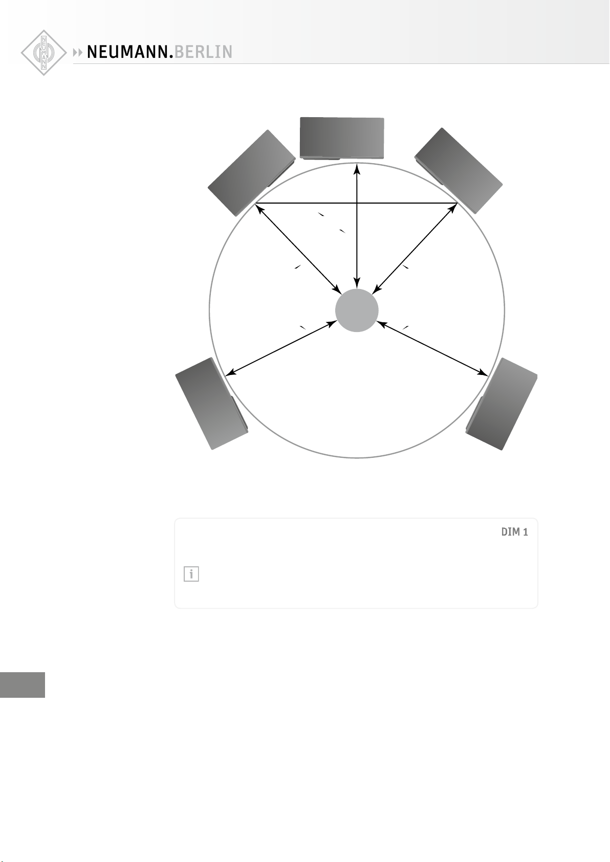
• 2.0 systems (stereo): ±30°, plus optional subwoofer(s)
• 5.1 systems:
ITU-R BS.775-1: 0°, ±30°, ±110° (±10°), plus optional subwoofer(s)
(center, front left/right, surround left/right)
ANSI/SMPTE 202M: 0°, ±22.5°, arrays to the surround left and to the surround right,
plus optional subwoofer(s)
• 7.1 systems: 0°, ±30°, ±90°, ±150°, plus optional subwoofer(s)
(center, front left/right, side left/right, back left/right)
EN
KH 420 | 13
The acoustical axis of the KH420 starts from the midpoint of the midrange and tweeter dri-
vers.
XAlways point the acoustical axis, in the horizontal and vertical planes, towards the listening
position.
The acoustical axis is a line perpendicular to the loudspeaker’s front panel along which
the microphone was placed when tuning the loudspeaker’s crossover during design.
Pointing the acoustical axis, in the horizontal and vertical planes, towards the listening
position or center of the monitoring area will give the best measured and perceived
sound quality.
XPosition the loudspeaker so that there is a direct line of sight from the listening position to
the bass, midrange and tweeter drivers.
Connecting audio signals
XAlways use good quality cables with the correct impedance and appropriate termination to
avoid signal drop outs and to achieve the maximum cable lengths shown below:
Signal (connector) Impedance Cable length Connection method
Analog (RCA) low up to 10 m
(30')
via an adapter (RCA-XLR)
to the ANALOG INPUT socket
(XLR) H(see page14)
Analog (XLR) low up to 100 m
(300')
directly to the ANALOG INPUT
socket (XLR) H(see page14)
Connecting analog signals
Digital signals can only be connected when the DIM1 module is installed.
XConnect the left and right output of your analog audio source to the XLR input sockets of the
respective loudspeaker.
XLR XLR
Signal B
Signal A
Analog Source
x = 16.5 cm
y = 49.9 cm
Connecting
XLRcables
Connecting
XLRcables
EN
14 | KH 420
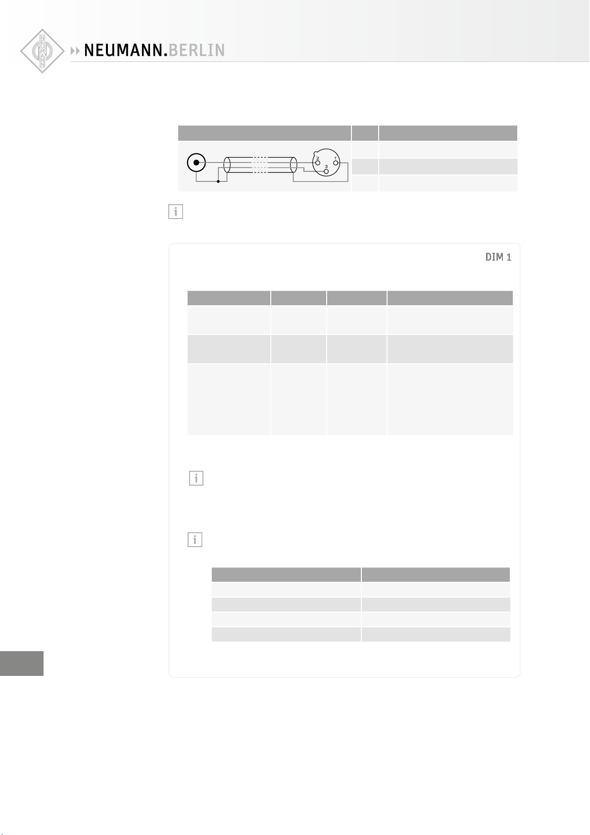
XUse an RCA-XLR adapter (not supplied) to connect unbalanced cables (e.g. RCA cables).
XUse the following wiring if you want to make your own RCA-XLR adapter:
Wiring Pin Signal
1Audio ground
2Signal +
3Signal −
If there is a humming sound from the loudspeaker, activate ground lift to disconnect
pin1 of the ANALOG INPUT socket (XLR)Hfrom the loudspeaker’s chassis ground.
Connecting digital signals to the KH420 with the DIM1 installed
XAlways use good quality cables with the correct impedance and appropriate termina-
tion to avoid signal drop outs and to achieve the maximum cable lengths shown below:
Signal (connector) Impedance Cable length Connection method
AES3 (BNC) 75 Ω up to 100 m
(300')
directly to the AES3 INPUT
socket (BNC)J of the DIM1
AES3 (XLR) 110 Ω up to 100 m
(300')
directly to the AES3 INPUT
socket (XLR)I of the DIM1
S/P-DIF (RCA) 75 Ω up to 10 m
(30')
via an adapter (RCA-BNC)
to the AES3 INPUT socket
(BNC)J
or via an adapter (RCA-XLR)
to the AES3 INPUT socket
(XLR)I of the DIM1
XConnect the digital AES3 or S/P-DIF-output signal of your audio source to the AES3
INPUT socket Ior Jof the DIM1. See figure below.
The DIM1 only supports non-encoded AES3 and S/P-DIF signals. Encoded sig-
nals such as MP3, DTS or Dolby Digital are not supported.
XMake an appropriate setting (“DIGITAL A” or “DIGITAL B”) on the SIGNAL SELECT
rotary switchL. The setting depends on the signal channel order and the loudspeaker
position.
Only one cable is needed for uncompressed AES3 and S/P-DIF digital signals
(single-wire mode). They contain two audio channels: “subframe A” and “sub-
frame B”. Usually, the audio channels are:
Subframe A Subframe B
Left Right
Center LFE
Surround left Surround right
Back left Back right
A clock input is not required because loudspeakers are not audio sources and the
converters are clocked to a very stable internally generated clock source.
DIM 1
DIM 1
DIM 1
1
1
1
1
1
1
1
1
1
1
1
1
1
1
1
1
1
1
1
1
1
1
1
1
1
M
M
M
M
M
M
M
M
M
M
M
M
M
M
M
M
M
M
M
M
M
M
M
M
M
M
M
M
M
M
I
I
I
I
II
I
I
I
I
I
I
I
I
I
I
I
I
D
D
D
D
D
D
D
D
D
D
D
D
D
D
D
D
D
D
D
D
D
D
D
D
D
D
D
Connecting
AES3 cables
Connecting
unbalanced cables
EN
KH 420 | 15
To connect an additional loudspeaker:
XUse the AES3 OUTPUT socket Kof the DIM1. See figure below.
XMake an appropriate setting (“DIGITAL A” or “DIGITAL B”) on the SIGNAL SELECT
rotary switch L.
XLR
or
BNC
In
BNC
Out
Subframe A - left signal
Subframe B - right signal
Digital Source:
AES 3 or S/P-DIF
BNC
In
RCA, BNC or XLR
Set back panel switch to “DIGITAL A” Set back panel switch to “DIGITAL B”
Connecting multiple KH420 loudspeakers together digitally via the DIM1
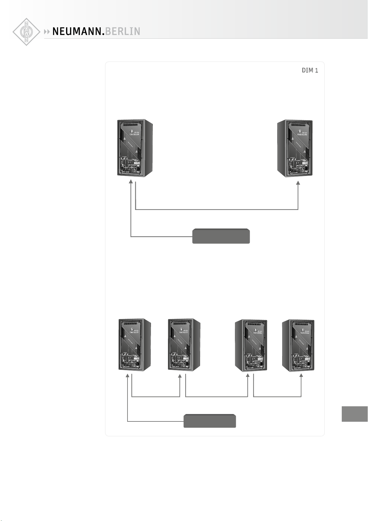
XUse the AES3 INPUT Jand OUTPUT socket (BNC) K. T-pieces are not required (see
figure below).
XMake an appropriate setting (“DIGITAL A” or “DIGITAL B”) on the SIGNAL SELECT
rotary switch L.
End of the line external termination is not required as the AES3 INPUT socket (BNC) J
already has an internal 75 Ω termination.
XLR
or
BNC
In
BNC
Out
Subframe A - left signal
Subframe B - right signal
Digital Source:
AES 3 or S/P-DIF
BNC
In
BNC
Out
BNC
In
BNC
Out
BNC
In
RCA, BNC or XLR
Set back panel switch to “DIGITAL A” Set back panel switch to “DIGITAL B”
DIM 1
DIM 1
DIM 1
1
1
1
1
1
1
1
1
1
1
1
1
1
1
1
1
1
1
1
1
1
1
1
1
1
M
M
M
M
M
M
M
M
M
M
M
M
M
M
M
M
M
M
M
M
M
M
M
M
M
M
M
M
M
M
I
I
I
I
I
I
I
I
I
II
I
II
I
I
I
I
D
D
D
D
D
D
D
D
D
D
D
D
D
D
D
D
D
D
D
D
D
D
D
D
D
D
D
EN

16 | KH 420
Setting the SIGNAL SELECT rotary switch L
XSelect one of the following settings, depending on your needs:
Setting Meaning
ANALOG ANALOG INPUT socket (XLR) H
DIGITAL A Digital subframe A, AES3 INPUT socket (BNC) Jor
AES3 INPUT socket (XLR)I
DIGITAL B Digital subframe B, AES3 INPUT socket (BNC) Jor
AES3 INPUT socket (XLR)I
DIGITAL A+B Digital subframe A summed with digital subframe B
and a 6dB attenuation, AES3 INPUT socket (BNC) Jor
AES3 INPUT socket (XLR)I
Each of these can be selected with and without delay added, so it is very quick to bypass
the delay.
The digital output is a buered copy of the digital input signal which can be used to feed
the digital signal onto other loudspeakersor products. There is no digital output from the
AES3 OUTPUT socket (BNC) Kwhen an analog signal is connected to the ANALOG INPUT
socket H, therefore the DIM1 cannot be used as an analog-to-digital converter. Delay is
not added to the digital output, so any delay required on subsequent loudspeakers in the
daisy chain should be made on those loudspeakers.
DIM 1
DIM 1
DIM 1
1
1
1
1
1
1
1
1
1
1
1
1
1
1
1
1
1
1
1
1
1
1
1
1
1
M
M
M
M
M
M
M
M
M
M
M
M
M
M
M
M
M
M
M
M
M
M
M
M
M
M
M
M
M
M
I
I
I
I
II
I
I
I
II
I
II
I
I
I
I
D
D
D
D
D
D
D
D
D
D
D
D
D
D
D
D
D
D
D
D
D
D
D
D
D
D
D
Connecting/disconnecting the KH 420 to/from the mains
power supply
To connect the KH 420 to the mains power supply:
XMake sure that the on/o switchE is set to “0”.
XConnect the IEC connector of the supplied mains cable to the mains socket D.
Power Source
E
D
XConnect the mains plug of the mains cable to a suitable wall socket.
To disconnect the KH 420 from the mains power supply:
XSet the on/o switch Eto “0”.
XPull the mains plug out of the wall socket.
EN

KH 420 | 17
Configuring and using the KH 420
Switching the KH 420 on/o
XSet the on/o switch to:
• “I” to switch on the loudspeaker. The Neumann logo lights up, provided that it has not
been switched o by means of the DISPLAY BRIGHTNESS switch 0 (see page 22).
• “0” to switch o the loudspeaker. The Neumann logo goes o.
There is an approximate five second delay before sound can be heard from the loud-
speaker in order to avoid noises (pops) from preceding equipment switched on at the
same time. Conversely, switching o the loudspeaker immediately mutes the audio.
Adjusting the frequency response
When all its acoustical controls are set to 0dB, the KH 420 loudspeaker is designed to have
a flat frequency response in anechoic conditions. When the loudspeaker is installed in your
monitoring environment, the response changes. The same loudspeaker installed in dierent
positions in the same room may require dierent acoustical control settings. In a symmetri-
cal installation, left/right pairs (front or back) will probably have the same acoustical control
settings.
XBefore using your loudspeaker system for the first time, calibrate the frequency response of
the loudspeakers in the room in order to obtain the desired response.
XRepeat the above step if you change the physical conditions in your studio.
XAt your listening position, determine the frequency response of each loudspeaker.
XUse the ACOUSTICAL CONTROLS switches Cto adjust the frequency response.
Recommended frequency responses measured at the listening position:
• Studio applications: flat
• Film applications: X-curve shape (see ANSI/SMPTE 202M)
• Home applications: subjective evaluation
EN

18 | KH 420
ACOUSTICAL CONTROLS
switches C
Function Possible settings
Bass Compensates for acoustical
loading in the low frequency
range due to nearby large solid
boundaries (e.g. walls).
0, −2.5, −5, −7.5dB
Mid Compensates for a “harshness” in
the sound quality experienced in
some installations. The source of
this is usually comb filtering due
to desktop and/or ceiling reflec-
tions.
0, −1.5, −3, −4.5dB
Treble Compensates for insucient or
excessive high-frequency
damping in the room.
+1, 0, −1, −2dB
Parametric EQ Compensates for low and low-mid
frequency anomalies.
Desktop loading typically causes
a wide bump 2-6dB high between
100 and 300Hz.
Reflections from nearby bounda-
ries (walls, floor, ceiling) cause
constructive and destructive
interference.
Strong room resonances are
audible and should be reduced
with the parametric EQ.
Gain: +4 to −12dB
Freq: O,
25 to 80,
50 to 160,
100 to 320Hz
Q: 1 to 8
PARAMETRIC EQUALIZER
GAIN [dB] Q
TREBLEMIDBASS
ACOUSTICAL CONTROLS [dB]
25-80
50-160
100-320
OFF
OUTPUT LEVEL INPUT GAIN
for 0 dBu
114
94
100
108
-12
-5
-2
0
+1
+2
+4
1
1.5
2
2.5
3
4
81
2
3
4
5
6
7
FREQUENCY FREQUENCY RANGE [Hz]
Position
25
32
40
45
52
65
80
25-80
50
64
80
90
105
130
160
50-160
100
130
160
180
210
260
320
100-320
1
2
3
4
5
6
7
-12
-4
-14
-10
-6
-2
[dB SPL at 1 m
for 0 dBu / -18 dB FS]
-1.0
-2.0
+1.0
-1.5
-3.0
-4.5
-2.5
-7.5
-5.0
0
00
Max. input level
24 dBu (*18 dBu for
analog delayed)
-8
EN
Table of contents
Other Neumann.Berlin Speakers manuals

Neumann.Berlin
Neumann.Berlin KH 80 DSP User manual

Neumann.Berlin
Neumann.Berlin KH 80 DSP User manual

Neumann.Berlin
Neumann.Berlin KH 310 A User manual

Neumann.Berlin
Neumann.Berlin KH 120 D User manual

Neumann.Berlin
Neumann.Berlin KH 120 A User manual

Neumann.Berlin
Neumann.Berlin KH 120 II AES67 User manual

Neumann.Berlin
Neumann.Berlin KH 120 II User manual

Neumann.Berlin
Neumann.Berlin KH 120 A User manual

Neumann.Berlin
Neumann.Berlin KH 80 DSP User manual

Neumann.Berlin
Neumann.Berlin KH 150 AES67 User manual


