Neumann.Berlin LH 45 Guide

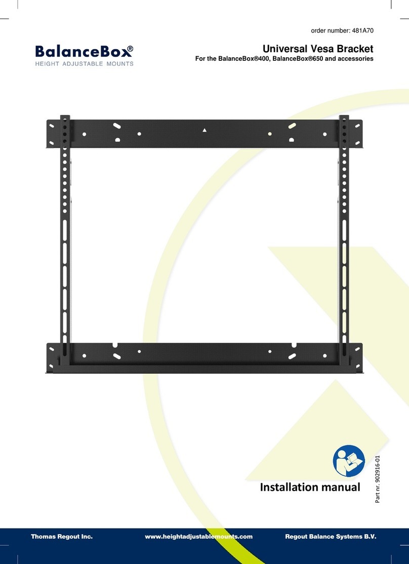
LH 45 Mounting manual
Wall Bracket
Important safety and mounting instructions
• Have the product mounted by a specialist.
•Due to his/her technical training, know-how and experience as well
as knowledge of relevant provisions, regulations and standards, the
specialist must be able to assess assigned tasks, recognize poten-
tial hazards and ensure appropriate safety measures. The following
safety and mounting instructions are addressed to this specialist.
•
Read and follow the safety and mounting instructions, keep these
instructions and always include them when passing the LH45 on
to third parties.
•
Also read and follow the installation instructions contained in the
operating manual of the mounted loudspeaker.
•When mounting, observe and follow the local, national and interna-
tional regulations and standards.
•
Do not install the LH45 in locations where it is exposed to externally
generated vibrations.
• Always use the original Neumann mounting hardware.
•Only mount one loudspeaker in combination with other accessories
from the Neumann mounting hardware range to the LH 45. The maxi-
mum permissible weight is 36 kg (79.4 lbs).
Download the PDF file “Hardware Mounting Matrix” from
www.neumann.com. Only combine the Neumann mounting
hardware as specified in the “Hardware Mounting Mat ix”.
•
The cylinder-shaped holder B is pre-mounted in the mid-position. If
you want to mount the holder in the front or rear position:
– Loosen the 4Allen screwsF of the locking ring C of the cylinder-
shaped holder B (see fi . 1) using the 4 mm Allen key G.
– Remove the locking ring.
– Loosen the 4Allen screws D (see fi .1) using the 5 mm Allen
key H.
– Move the cylinder-shaped holder B to the desired position.
– Tighten the 4 Allen screws D with a torque of 6 Nm and fasten
the locking ring C (see fi . 2).
If you mount the cylinder-shaped holder B in the rear position,
the horizontal rotation angle is reduced (see fi .2).
• Attach the LH 45 to a vertical surface.
– The surface must be able to carry the weight of the loudspeaker
plus the weight of all parts used. Calculate the weight and addi-
tionally consider the leverage.
– Use fastening elements (not supplied) that are sufficien y
dimensioned for the calculated weight.
– Use all 4 mounting points I, II, III and IV to attach the LH 45 to
the vertical surface.
•Mount a Neumann mounting hardware that is suitable for use
with the LH 45 to your loudspeaker (see the “Hardware Mounting
Matrix”).
–
Also read and follow the safety and mounting instructions con-
tained in the operating manual of the selected Neumann mounting
hardware.
– Only tilt the loudspeaker when it is properly fastened to the
LH45 and to additional Neumann mounting hardware, and when
it is secured.
– Tighten all supplied screws/nuts with a torque of 20Nm.
•Mount the loudspeaker plus additionally attached hardware to the
cylinder-shaped holder B of the LH 45. To do so, proceed as shown
in figs.3 to 7:
CAUTION
Danger of injury and material damage
due to dropping of the loudspeaker!
Unless the additional hardware is properly fastened to the cyl-
inder-shaped holder B of the LH 45, the loudspeaker together
with the mounting hardware can drop down.
XHave the loudspeaker held by a second specialist who is
physically able to do so. The requirements mentioned earlier
also apply to this specialist.
XWhen mounting the loudspeaker, provide a sufficien addi-
tional protection against dropping.
– Position the locking ring of the cylinder-shaped holder B in the
upper position and tighten one of the 4 Allen screws so that the
locking ring cannot work loose and fall off.
– Place the loudspeaker plus additionally attached hardware onto
the cylinder-shaped holder B as shown in figs. 3, 4 and 5
– Loosen the previously tightened Allen screw F of the locking
ring C (see fi . 6).
– Lower the locking ring into position (see fi .7).
– Rotate the loudspeaker in the desired direction.
– Tighten the 4 Allen screws with a torque of 15Nm. The loud-
speaker with attached additional hardware is now properly fas-
tened to the cylinder-shaped holder B.
•
Use safety wires to additionally protect the loudspeaker and the
mounting hardware against tipping/dropping. The safety wires, rope
terminations and coupling links must comply in their dimensioning
and condition with the regulations and standards of the country in
which they are used and must reliably prevent tipping/dropping of
the attached loudspeaker and mounting hardware.
• If necessary, vertically tilt the loudspeaker to the desired angle.
• Make sure that ...
–
the LH 45, the associated mounting hardware and the loudspeaker
cannot tip over or drop down, even if the power or audio cables
are pulled;
–
you replace the safety wires and coupling links by new ones when
they have prevented tipping/dropping;
–
you check every 3 months if all screws are properly tightened
and if the LH45 and associated mounting hardware, additional
fastening elements, safety wires and coupling links, as well as the
loudspeaker are in proper condition.
In case of any damage or any deviation from the safety and mounting
instructions, immediately dismount the loudspeaker, the LH45 and
the additional mounting hardware used.
EN
GEORG NEUMANN GMBH · LEIPZIGER STR. 112 · 10117 BERLIN · GERMANY
TEL +49 (0)30 / 45 77 24-0 · FAX -50 · [email protected] · WWW.NEUMANN.COM
10/15 · 549102/A02

Delivery includes
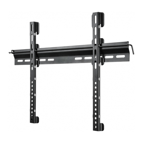
A: 1 x LH45 wall bracket
B: 1 x cylinder-shaped holder, pre-mounted
C: 1 x locking ring, pre-mounted
D: 4 x M5 x 16 Allen screws for screwing the
cylinder-shaped holder to the LH 45, pre-mounted
E: 4 x metal washers, pre-mounted
F: 4 x M8 x 10 Allen screws for screwing the locking ring to
the cylinder-shaped holder B, pre-mounted
G: 1 x 4 mm Allen key
H: 1 x 5 mm Allen key
Specification
Weight 3 kg (6.6 lbs)
Dimensions 570 x 125 x 405 mm (H x W x D)
22 1/2" x 4 7/8" x 16" (H x W x D)
Max. load 36 kg (79.4 lbs)
Guarantee
For the current terms and conditions of the product guarantee please
visit www.neumann.com.

1
2
I
II
III IV
4 mm
G
4 mm
G
H
5 mm H
5 mm
B
D
E
E
D
C
A
B
D
E
FC
6 Nm
6 Nm
F
F
F
F

3
5 6
7
4
15 Nm
C
F
F
Example/Beispiel/
Exemple/Ejemplo:
LH 47

