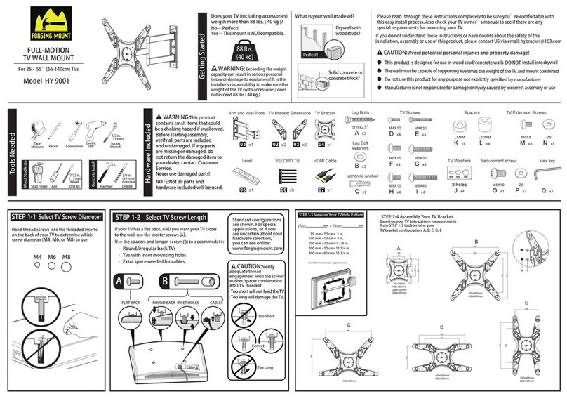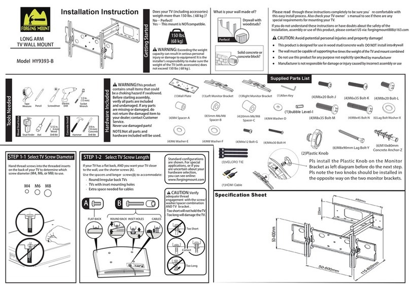
05
16 in.
(406 mm)
2-1 2-2 2-3 2-4
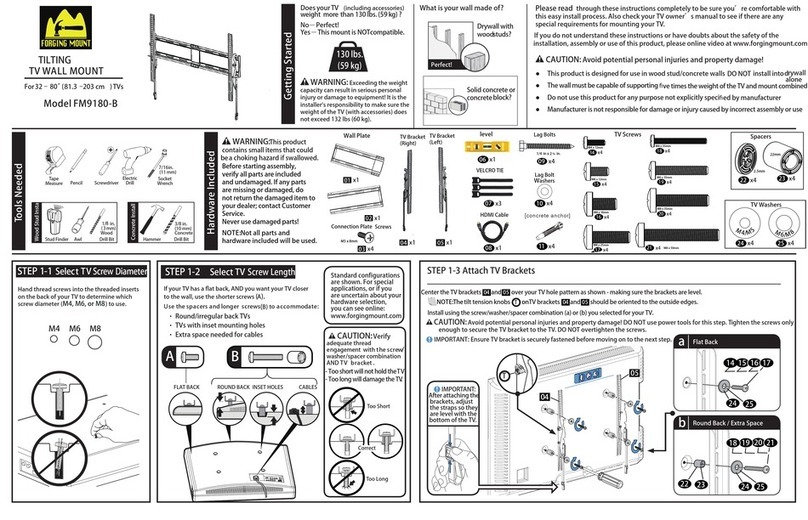
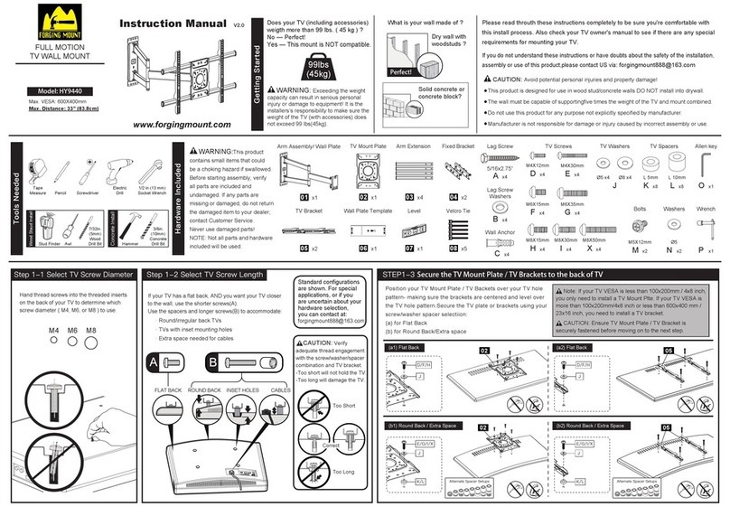
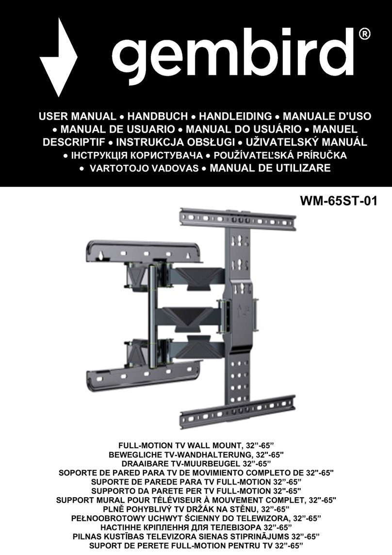
STEP 4 Attach TV Brackets to TV back STEP 5 Attach TV plate to the arm assembly
Made in China.
Position the template at your desired height
and line up the holes with your stud center line.
Level the wall plate and mark the holes.
Drill five pilot holes using a 7/32 in (5.5mm) diameter drill bit.
of 3 in.(75 mm).Be sure to drill into the center of the stud.
IMPORTANT: Pilot holes must be drilled to a depth
CAUTION: property damage!
●Minimum solid concrete thickness: 8 in. (203 mm).
●Minimum concrete block size: 8 x 8 x 16 in. (203 x 203 x 406 mm)
●Minimum horizontal space between fasteners: 16 in
(406 mm).
●Mount wall plate directly onto the concrete surface.
Position template 04 at your
desired height. Level, then
mark the five hole locations.
Drill five pilot holes using a 3/8 in.
(10 mm) masonry drill bit.
Min.
8 in.
(203 mm)
Min. 8 in.
(203 mm)
Min. 16 in.
(406 mm)
CAUTION: Be sure the anchors are
seated flush with the concrete surface.
Install wall plate
DO NOT over-tighten the screws.
and screws
holding power of screws
with five washers
01
IMPORTANT : Ensure TV bracket is securely fastened before moving on to the next step.
CAUTION:Avoid potential personal injuries and property damage!
DO NOT use a power screwdriver for this step
STEP 2 Wall Plate Install( Wood Stud )
STEP 3 Wall Plate Install( Solid Concrete or Concrete Block )
½ x 3½ in. (38 x 89 mm)
K MUST BE
CAUTION: Avoid potential personal injuries
and property damage!
●Drywall covering the wall must not exceed
5/8 in. (16 mm)
●Minimum wood stud size: common 2 x 4 in.
(51 x 102 mm) nominal 1
CAUTION: A
01 .
void potential personal injury
or property damage! All lag bolts
firmly tightened to prevent unwanted
movement of the wall plate
CAUTION: Ensure the wall plate is securely
fastened to the wall before continuing on to the
next step. the studs by finding the stud edges using an awl,
a thin nail, or an edge-to-edge stud finder.
Locate your studs. Verify and mark the center of 04
Install wall plate
washers
they are pulled firmly a gainst the wall plate
.Tighten the lag bolts only until
using lag bolt and
01
01
01
K
M
L
22
M
K
3 in. (75mm)
7/32 in.
(5.5 mm)
Avoid potential personal injuries and
3-1 3-2 3-3
04
Min. 16 in.
(406 mm)
drilled to a depth of 3 in ( 75 mm ).
Never drill into the mortar between blocks.
IMPORTANT:Pilot holes must be
04
L
Insert five concrete anchors
( 10x60mm ) to the wall
CAUTION: Improper use could reduce the
K
aFlat Back
J
DF
H
bRound Back/Extra Space
JB
C
E
GI
STEP 6 Attach TV to the TV plate Sub-assembly
and cable management Loosen the nuts with a wrench to adjust the appropriate tilt
Angle and tighten the nut
STEP 7 Tilt and level adjustment
O
Leveling
3-3
A
Use socket wrench to adjust the 4 nuts for TV level
S1 S2
Hang into , and using Wrench secure with
pre-assembled Nuts and washers .
03 01
Level
O
Tilt adjusting
Socket Wrench O
Cable managerment
Insert the safety lock in the bottom of
the bracket and then tighten the screws.
“Be gentle”
N
16”(406mm)
