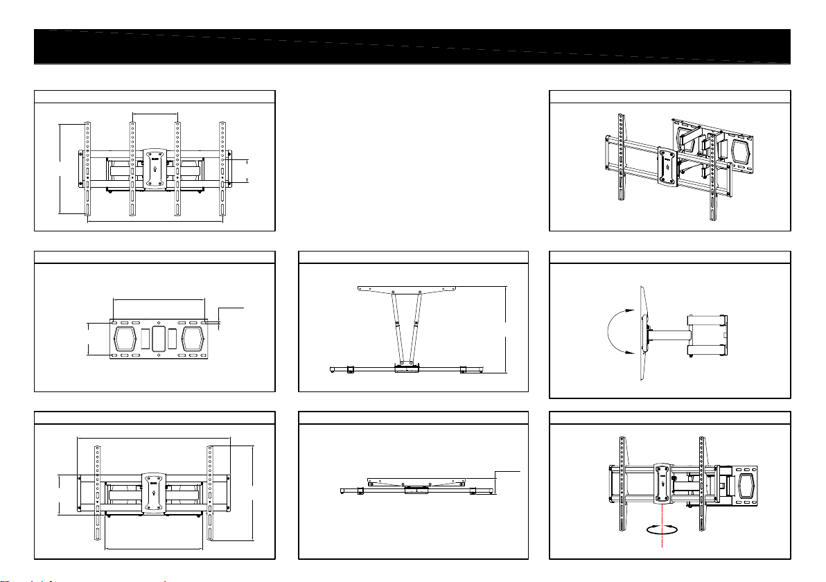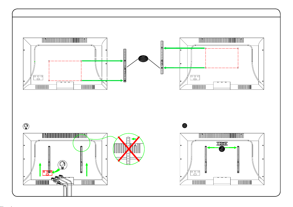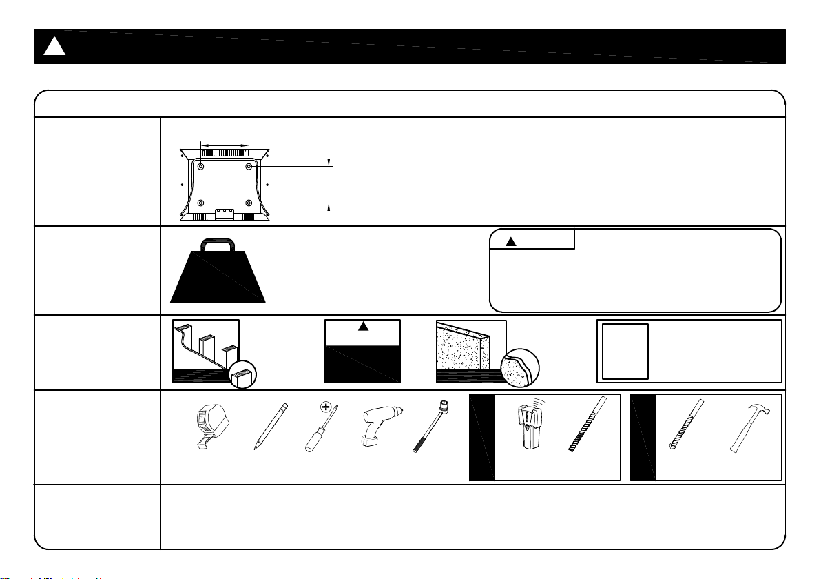
MAX:600mm/23.62"
(MIN:200mm/7.87")
MAX:400mm/15.75"
(MIN:100mm/3.94")
Before getting started, let’s check below lists to make sure it is just right for you!
2
3
4
5
Does your TV
(including accessories)
weigh MORE than
120 lbs. (54.5 kg)?
What is your
wall made of?
Do you have
all the tools
needed?
(NOT INCLUDE)
CAUTION
No? Perfect – you may continue.
Yes? This mount is NOT compatible.
Drywall with
wood studs?
CAUTION: DO NOT exceed the maximum weight
indicated. This mounting system is intended for use only
with the maximum weights indicated. Use with products
heavier than the maximum weights indicated may result
in collapse of the mount and its accessories, causing
possible injury.
?
● This product is designed for use in wood stud, solid concrete walls - DO NOT install into drywall alone
● The wall must be capable of supporting five times the weight of the TV and mount itself
● Do not use this product for any purpose not explicitly specified by manufacturer
● Manufacturer is not responsible for damage or injury caused by incorrect assembly or use
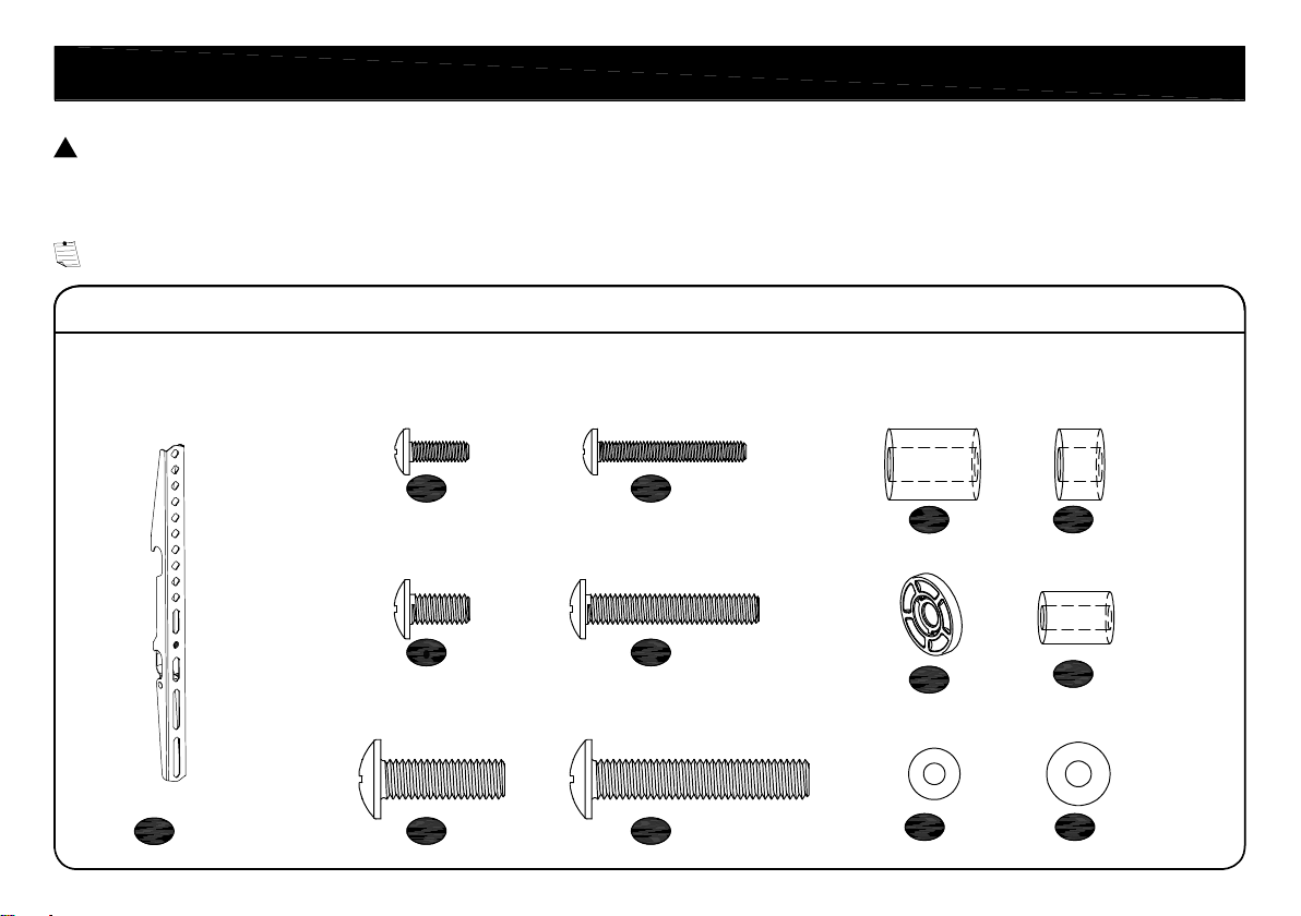
1
Check your TV
VESA is within
Min and Max size
No? This mount is NOT compatible.
Yes? Perfect !
Tape
Measure Pencil Screw
driver
Electric
Drill
1/2 in.
(13 mm)
Socket
Wrench
Unsure?
Mail to us via Amazon.
CAUTION: PLEASE READ ENTIRE MANUAL PRIOR TO USE AND SAVE THESE INSTRUCTIONS
!
Per fect !
CAUTION:
DO NOT
install into
drywall alone
!
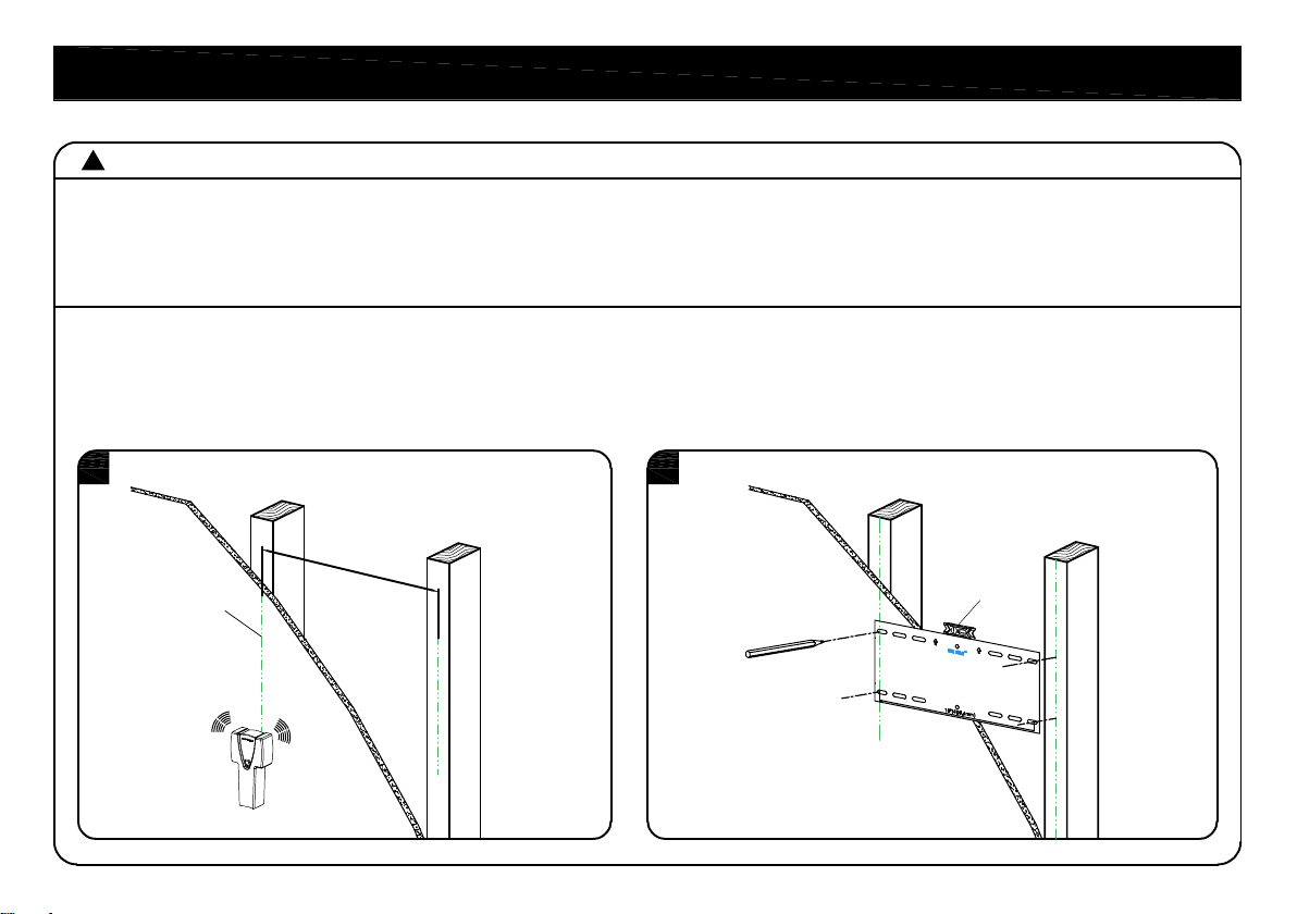
Stud
Finder
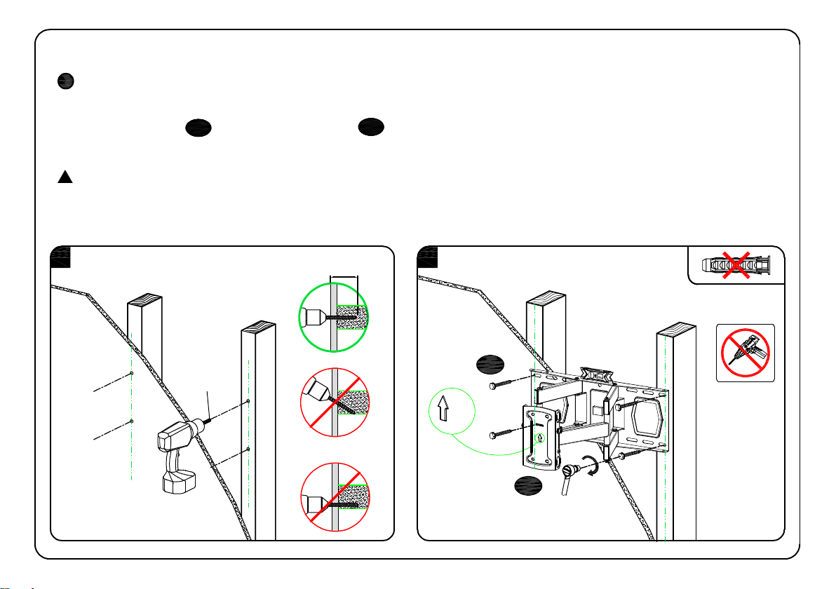
7/32 in.
(5.5 mm)
Wood
Drill Bit
3/8 in.
(10 mm)
Masonry
Drill Bit
Hammer
Concrete Install
Wood Stud Install
Solid concrete
Per fect !
120 LBS
(54.5 kg)
!
2