Neurosoft Neuro-MEP User manual

Technical Manual
Neuro-MEP
Neuro-ERG
Digital Neurophysiological Systems
TM006.01.005.00
3
(27.08.2013
)

Neurosoft Ltd. © 2014
5, Voronin str., Ivanovo, 153032, Russia
P.O. Box 10, Ivanovo, 153000, Russia
Phone: +7 (4932) 24-04-34 Fax: +7 (4932) 24-04-35
E-mail: com@neurosoft.ru Internet: www.neurosoft.ru

3
Contents
Introduction............................................................................................................... 4
1. Description and Operation................................................................................ 5
1.1. Function........................................................................................................ 5
1.2. Specifications ...............................................................................................6
1.3. Delivery Set................................................................................................ 10
1.4. Arrangement and Operation ....................................................................... 16
1.5. Connectors and Indicators Function............................................................ 19
1.6. Synchronization with Stimulators of Third-party Manufacturers................... 22
1.7. Synchronization Use with Neuro-MEP.NET Software ................................. 23
2. Mounting and Setting...................................................................................... 24
2.1. Personnel Requirements Conducting Mounting and Setting....................... 24
2.2. Room Selection and Placement.................................................................. 25
2.3. Unpacking and Check of Delivery Set......................................................... 27
2.4. Mounting and Connection to Computer....................................................... 28
3. Proper Use....................................................................................................... 32
3.1. Safety Measures When Using Digital System............................................. 32
3.2. Setting-Up Procedures................................................................................ 32
3.3. Troubleshooting.......................................................................................... 33
3.4. Exams Performing Using Digital System..................................................... 39
3.5. Actions in Emergency................................................................................. 39
4. Servicing.......................................................................................................... 40
4.1. General Requirements................................................................................ 40
4.2. Digital System Servicing............................................................................. 40
4.3. Conservation .............................................................................................. 40
5. Current Repair ................................................................................................. 41
5.1. General Requirements................................................................................ 41
5.2. Cables, Adapters and Linkers Repair.......................................................... 41
5.3. Amplifier Interface Cable Repair (USB Cable) ............................................ 41
5.4. Auditory Stimulator Repair.......................................................................... 42
5.5. LED Goggles Repair................................................................................... 42
5.6. LED Penlights Repair ................................................................................. 43
5.7. Ganzfeld Stimulator Repair......................................................................... 44
5.8. Electro Stimulating Electrode Repair (Stimulus Probe) ............................... 44
6. Packing and Transportation ........................................................................... 45
7. Utilization......................................................................................................... 45
8. Delivery Set and Package Data....................................................................... 45
9. Acceptance Certificate.................................................................................... 46
10. Delivery Certificate.......................................................................................... 46
11. Storage Data .................................................................................................... 46
12. Warranty........................................................................................................... 47
13. Reclamation Data ............................................................................................ 48
14. Repair Data ...................................................................................................... 50
Appendix 1. Electromagnetic Emissions and Immunity ...................................... 51

Neuro-MEP, Neuro-ERG (Technical Manual)
4
Introduction
This technical manual (further "manual") is the combined document describing opera-
tion and servicing of multifunctional digital neurophysiological systems for EMG, EP,
ERG and OAE Neuro-MEP-4, Neuro-MEP-8 and Neuro-ERG digital systems (here-
inafter referred to as "digital systems").
The document certifies technical parameters of digital systems, which are guaranteed
by the manufacturer.
Do not start working with the digital system before you have
read this document!
You can send your responses and recommendations to the following address:
P.O. Box 10, Ivanovo, 153000, Russia
or by e-mail:
You can find additional information on Neurosoft products on our website:
www.neurosoft.ru
or ask questions by phone:
+7 (4932) 24-04-37 (Service Department)
+7 (4932) 24-04-34
You can also contact SAS Neuromed Company, Authorized European Representa-
tive of Neurosoft Company (to Mr. Pierre Scholl) by the following address:
Chemin du tomple
84330 Le Barroux, France
Phone: +490-650-470, +622-748-384
Fax: +490-650-470
E-mail: bscho[email protected]

Description and Operation
5
1. Description and Operation
1.1. Function
Digital system Neuro-MEP-4 is intended for study of electrical activity of muscles and
nerves and also somatosensory, visual, auditory evoked potentials (EP), magnetic
EP, electroretinogram (ERG), otoacoustic emission (OAE) by 1-4 channels and
Neuro-MEP-8 is by 1-8 channels. It is done by biopotentials acquision and input into
PC, and measurement, calculation and analysis of its parameters.
Digital system Neuro-ERG is based on Neuro-MEP digital system and intended for
electroretinography, flash and reversal pattern visual evoked potentials (VEP) and
EOG studies.
The digital systems can be used in the patient care institutions, diagnostics centers,
neurosurgical hospitals and experimental laboratories of the research institutions for:
•brain functional state study;
•neuromuscular system study (Neuro-MEP digital system);
•study of auditory (Neuro-MEP digital system) and visual tracts.
The general properties, when carrying out the exams:
•1-4/8 channel biopotentials recording in any unshielded room;
•Photic-, auditory (Neuro-MEP digital system), electrical stimulation (Neuro-MEP
digital system) and stimulation carrying out with the use of checkerboard reversal
pattern;
•Long-, middle-, short-latency flash and reversal pattern visual, auditory
(Neuro-MEP digital system), cognitive (P300, MMN, CNV) (Neuro-MEP digital sys-
tem), somatosensory (Neuro-MEP digital system) evoked potentials recording;
•Skin galvanic responses recording (Neuro-MEP digital system);
•Surface EMG recording (Neuro-MEP digital system);
•Stimulation EMG recording (Neuro-MEP digital system);
•Repetitive stimulation (Neuro-MEP digital system);
•Needle EMG recording (Neuro-MEP digital system);
•Electroretinogram study;
•Otoacoustic emission study (Neuro-MEP digital system);

Neuro-MEP, Neuro-ERG (Technical Manual)
6
•Exam report generation;
•Preview, storage and print of the recorded traces, results of their analysis and exam
reports.
1.2. Specifications
Table 1. Main Specifications.
Parameters
Values
Biopotentials Acquisition Channels
Number of channels 4/8
*
Sampling rate
−if you use Neuro-MEP software
−
if you use Neuro-MEP.NET software
200 Hz−40 kHz
200 Hz−40 (160) kHz
A/D converter 16 bit
Voltage range 20 µ−50 mV
Ratio error of voltage measurement:
−in the range from 20 up to 100 µV
−
in the range from 0.1 up to 50 mV
within ±15%
within ±5%
EP voltage range at averaging 0.1−400 µV
Ratio error of EP voltage measurement at
averaging within ±10%
Common-mode rejection not less than 100 dB
Noise level, rms not more than 0.5 µV
Input impedance not less than 200/1000** MΩ
Amplifiers input capacitance not more than 25/22** pF
Patient leakage current not more than 0.1 µA
Bandpass flatness:
−in the band from 0.02 up to 0.05 Hz and
from 5 up to 10 kHz
−
in the band from 0.05 Hz up to 5 kHz
from –30 up to +5%
from –10 up to +5%
High pass filter 0,02;0,05;0,1; 0,2; 0,3; 0,5; 1; 2; 3; 5; 10; 20;
30; 50; 100; 200; 300; 500; 1000;
2000; 3000 Hz
Low pass filter 10; 20; 35; 50; 75; 100; 150; 200; 300; 500
Hz; 1; 2; 3; 5; 10 kHz
Sensitivity
−if you use Neuro-MEP software
−if you use Neuro-MEP.NET software
0,05; 0,1; 0,2; 0,5; 1; 2; 5; 10; 20; 50; 100;
200; 500 µV/div; 1; 2; 5; 10; 20; 50 mV/div.
0,05; 0,075; 0,1; 0,15; 0,2; 0,25; 0,4; 0,5;
0,75; 1; 1,5; 2; 2,5; 4; 5; 7,5; 10; 15; 20; 25;
40; 50; 75; 100; 150; 200; 250; 400; 500; 750;
µV/div.; 1; 1,5; 2; 2,5; 4; 5; 7,5; 10; 15; 20; 25;
40; 50 mV/div.
Ratio error of sensitivity within ±5%

Description and Operation
7
Table 1. Continued.
Parameters
Values
Sweep speed 0.1, 0.15, 0.2, 0.25, 0.4, 0.5, 0.75, 1, 1.5, 2,
2.5, 4, 5, 7.5, 10, 15, 20, 25, 40, 50, 75, 100,
150, 200, 250, 400 ms/div.;
0.5, 0.75, 1, 1.5, 2 s/div.
Ratio error of sweep speed within ±1%
Suppression ratio of power frequency by
notch filter not less than 40 dB
Electrical Stimulator
Stimulus amplitude 0.1−100 mA
Absolute deviation of stimulus amplitude ±0.1 mA
Stimulus duration
−if you use Neuro-MEP software
−
if you use Neuro-MEP.NET software
50 −5000 µs
100 −50000 µs
Absolute deviation of stimulus duration ±5 µs
Stimulus frequency at repetitive stimulation
−if you use Neuro-MEP software
−
if you use Neuro-MEP.NET software
0.05−50 Hz
0,01−100 Hz
Relative deviation of stimulus frequency
during repetitive stimulation within ±1%
Interstimuli interval at paired stimulation
−if you use Neuro-MEP software
−
if you use Neuro-MEP.NET software
10−5000 ms
10−100000 ms
Burst stimulation:
−pulse frequency
•if you use Neuro-MEP software
•if you use Neuro-MEP.NET software
−maximal burst duration
•if you use Neuro-MEP software
•if you use Neuro-MEP.NET software
does not support
40−1000 Hz
does not support
50 ms
Auditory Stimulator
Number of channels 2 (right and left)
Stimulation level 0−127 dB SPL (ТА-01)
0−130 dB SPL (TDH-39)
Stimulus frequency
−if you use Neuro-MEP software
−
if you use Neuro-MEP.NET software
0.05−30 Hz
0.01−100 Hz
Relative deviation of stimulus frequency within ±1%
Stimulus duration
−if you use Neuro-MEP software
−
if you use Neuro-MEP.NET software
100−50000 µs
50−90000 µs
Relative deviation of stimulus duration within ±15%
Left/right/double-sided stimulation yes

Neuro-MEP, Neuro-ERG (Technical Manual)
8
Table 1. Continued.
Parameters
Values
Photic Stimulator
Maximum brightness of:
−LED goggles
−mini-ganzfeld stimulator
(1100 ± 110) cd/m2
(1500 ± 150) cd/m2
Maximum luminescence power of:
−white penlight
−red penlight
−blue penlingt
−
green penlight
(0.2 ± 0.05) cd
(0.3 ± 0.075) cd
(0.15 ± 0.0375) cd
(0.2 ± 0.05) cd
Brightness control range -3…0 log units
Stimulus duration
−if you use Neuro-MEP software
−
if you use Neuro-MEP.NET software
0.1−50 ms
0.05−1500 ms
Relative deviation of stimulus duration within ±10%
Stimulus frequency
−if you use Neuro-MEP software
−
if you use Neuro-MEP.NET software
0.05−100 Hz
0.01−100 Hz
Relative deviation of stimulus frequency within ±1%
Left/right/double-sided stimulation by LED
goggles yes
Pattern Stimulator
Stimulation frequency
−if you use Neuro-MEP software
−
if you use Neuro-MEP.NET software
0.1−5 Hz
0.1−5 Hz
Relative deviation of stimulation frequency within ±10%
Pattern resolution:
−standard stimulator
−
high resolution stimulator
320×240 pixels, 15 colors
800×600 pixels, 16 millions of colors
OAE Probe
Stimulus intensity
−if you use Neuro-MEP software
−
if you use Neuro-MEP.NET software
0−80 dB
does not support
Absolute deviation of stimulus intensity within ±3 dB
Stimulus duration
−if you use Neuro-MEP software
−if you use Neuro-MEP.NET software
100−50000 µs
does not support
Relative deviation of stimulus duration within ±15%
Stimulus frequency
−if you use Neuro-MEP software
−
if you use Neuro-MEP.NET software
0.05−50 Hz
does not support
Relative deviation of stimulus frequency
within ±15%
Receiver bandpass flatness:
−from 500 up to 2500 Hz
−
from 2500 up to 4500 Hz
not more than 10 dB
not more than 20 dB
Description and Operation
9
Table 1. Continued.
Parameters
Values
Microphone bandpass flatness:
−
in the band from 500 up to 4500 Hz
not more than 6 dB
General Parameters and Characteristics
Interface USB
Supply voltage:
−Electronic units
−Desktop PC-based system
−Notebook PC-based system
5 V DC
220/230 V AC (50 Hz)
110 V AC (60 Hz)
220/230 V AC (50 Hz)
110 V AC (60 Hz)/
int. battery
Dimensions:
−Amplifier unit
−Auditory-visual stimulator unit
−Electrical stimulator control unit
190×140×50 mm
155×105×40 mm
155×105×40 mm
Weight:
−Amplifier unit
−Auditory-visual stimulator unit
−Electrical stimulator control unit
not more than 1 kg
not more than 0.5 kg
not more than 0.5 kg
Safety BF type
* if two 4-channel amplifier units are used (Neuro-MEP-8 digital system).
** if amplifier unit with NSFT 006201.012 and higher is used.
Safety and Electromagnetic Compatibility
Electromagnetic compatibility (EMC) is provided by IEC 60601-1-2:2007 requirements
fulfillment.
The digital system is intended for operation in electromagnetic environment, which
special features are specified in Appendix 1.
Portable and mobile RF communication equipment can affect the system operation.
The use of the equipment not listed in tables 2 and 3 of the present technical manual
may result in increased emission and system decreased immunity.
As for safety, the digital system satisfies IEC 60601-1:1988 + A1:1991 + A2:1995,
IEC 60601-1-1:2000 and IEC 60601-2-40:1998 requirements. The electronic unit is
supplied by regulated power supply through USB interface, it has double isolation and
BF type work parts according to IEC 60601-1.
Interpretation of Symbols on Electronic Units:
−
−−
−
Attention: consult user and technical manuals.
−
Work parts of BF type according to IEC 60601-1.

Neuro-MEP, Neuro-ERG (Technical Manual)
10
−
Mark of conformance to Russian standards requirements GOST R.
−
Mark of measuring device with approved type.
−
Mark of conformance to 93/42/EEC “Concerning Medical Devices” directive.
−
Mark of conformance to 2002/96/EC “On waste electrical and electronic
equipment (WEEE)” directive.
1.3. Delivery Set
The delivery sets of Neuro-MEP-4,Neuro-MEP-8,Neuro-ERG digital systems in-
clude the electronic units of an amplifier, electrical stimulator and auditory-visual stim-
ulator, patient button, footswitch, dedicated keyboard and software, which can be de-
livered to the customer both jointly and separately, and also components and bought
articles. The delivery sets depending on the functional variant are represented in the
Table 2 and Table 3.
The Table 2 and Table 3 include the following:
1. Neuro-MEP-4 digital EMG and EP system;
2. Neuro-MEP-8 digital EMG and EP system;
3. Neuro-MEP-4 digital EMG and EP system (Neuro-MEP-4/S delivery set)
4. Neuro-MEP-8 digital EMG and EP system (Neuro-MEP-8/S delivery set)
5. Neuro-ERG digital ERG system.
6. Neuro-MEP-4 digital EMG and EP system (Neuro-EMG delivery set)
7. Neuro-MEP-4 digital EMG and EP system (Neuro-EP delivery set)
Table 2. Base Delivery Set
Name
Document code or main
specifications
Number
,
pcs.
1/2
3/4
5
6
7
Neuro
-
MEP
amplifier unit NSFT 006201.012
1/2
1/2
1 1 1
Neuro
-
MEP
auditory-visual stimulator
unit NSFT 025201.010 1 1 1 - 1
Neuro
-
MEP
electrical stimulator control
unit NSFT 024201.017 1 1 - 1 1
Holder NSFT 016201.038
NSFT 016201.038-01 1 1 1 1 1
Cleat for 2 amplifier units fixation on
holder NSFT 006200.003 -/1
-/1
- - -
Holder fastener NSFT 006200.002 -/1
-/1
1 1 1
Description and Operation
11
Table 2. Continued.
Name
Document code or main
specifications
Number
,
pcs.
1/2
3/4
5
6
7
Holder for dedicated keyboard
NSFT 035221.001
1 - - 1 -
Electrode holder NSFT 016221.023 1 1 1 1 -
Patient button NSFT 028201.006 1 1 - - 1
Footswitch
NSFT 028353.004
NSFT 028353.003
1 - - 1 -
USB cable (A→B) reinforced NSFT 007103.005-01 2 2 1 1 2
USB cable (A→B) standard 1.8 m 1 - - 1 -
SVGA extension cable 3 m 1 1 1 - 1
Auditory stimulator for EP
(headphones) NSFT 032305.005 (TDH-39)
NSFT 032305.001 (TDH-01) 1 1 - - 1
Visual stimulator
(LED goggles) NSFT 005302.001 1 1 1 - 1
Loudspeaker Edifier R18USB
(2×1.2W, wood, wired
remote control, USB)
2 2 - 2 -
Bluetooth adapter Dongle 100 m Class 1,
V2.1, CSR chipset 1 - - 1 -
Electrode gel
1)
TC 9398-005-76063983-2005,
250 g 1 1 - 1 1
Electrode adhesive paste
1)
TEN20, 114 g 1 1 1 1 1
TC 9398-007-76063983-2005,
120 g
Abrasive paste for skin preparation
1)
Everi (Italy) 1 1 1 1 1
Medical tape
1)
Transpore (3M Company, 3M
Health Care, USA) 1 1 1 1 1
Set of Electrodes and Accessories for EMG and EP Studies
Stimulation bar electrode with
replaceable steel and felt stimulation
pads (adult)
1)
TC 9442-990-13218158-2008
(NSFT 990998.009 (SBE-2) 1 1 - 1 1
Adjustable electro stimulating probe
NSFT 056998.001 (AESP-1)
1 - - 1 -
Stimulation electrode with steel
stimulation points (adult)
1)
TC 9442-990-13218158-2008
(NSFT 990106.019-25 (SSE-2))
- 1 - - -
Cup EP electrode with cable
1)
NSFT 990998.023 (set)
- - 1 - -
NSFT 990998.023 (set)
1/2
1/2
- 1 1
NSFT 990106.029-01.10 (EEP-2)
NSFT 990106.072-01.10 (EEP-2)
8/16
pcs.
8/16
pcs.
5
pcs.
8
pcs.
8
pcs.

Neuro-MEP, Neuro-ERG (Technical Manual)
12
Table 2.Continued.
Name Document code or main
specifications
Number
,
pcs.
1/2
3/4
5
6
7
Ring electrode (wide) with cable
1)
TC 9442-990-13218158-2008
(NSFT 990998.004 (RE-2))
1 1 - 1 -
Ground electrode with cable (pediatric)
(250 mm)
1) TC 9442-990-13218158-2008
(NSFT 990998.007 (GE-1))
1 1 - 1 -
Ground electrode with cable (adult)
(400 mm)
1) TC 9442-990-13218158-2008
(NSFT 990998.006 (GE-2))
1 1 - 1 -
Bar electrode (adult)
1
)
TC 9442-990-13218158-2008
(NSFT 990998.003 (BE-2))
2
2
)
2
2
)
- 2
2
)
-
Bar electrode (pediatric)
1
)
TC 9442-990-13218158-2008
(NSFT 990998.002 (BE-1))
Surface electrode
1
)
TC 9442-990-13218158-2008
(NSFT 990998.001 (SE-1))
2 2 - 2 -
Reusable concentric needle electrode Alpine Biomed Corp. (Denmark)
20, 30, 40 and 65 mm 2 2 - 2 -
Adapter for reusable needle electrode
connection NSFT 006103.009 1 1 - 1 -
Disposable concentric needle
electrode Alpine Biomed Corp. (Denmark)
25, 37, 50 and 75 mm 25
25
- 25
-
Adapter for disposable needle
electrode connection NSFT 006103.013 1 1 - 1 -
Disposable surface electrode F 3001, FIAB (Italy)
1
pack
1
pack
- 1
pack
-
Adapter for disposable electrodes
connection with Alligator clip (red,
black)
NSFT 990103.027-03.02
NSFT 990103.022-03.02 2 2 - 2 -
NSFT 990103.027-04.02
NSFT 990103.022-04.02 2 2 - 2 -
Pup-jack linker NSFT 006103.019 2/5
2/5
1 2 1
Measuring reel 1 m 1 1 - 1 -
Marker Red 1 1 - 1 -
Set of Accessories for ERG Studies Neuro-ERG
Corneal “loop” electrode NSFT 006106.005 - - 25 - -
Corneal “hook” electrode NSFT 006106.004 - - 5 - -
Adapter for corneal electrode
connection NSFT 006103.011 - - 2 - -
Ear EEG electrode
TC 9442-016-13218158-2003
(NSFT 015106.015)
- - 2 - -
Cable for bridge or ear EEG electrode NSFT 990103.036-01.10 - - 2 - -
Forehead and chin support assembly NSFT 016998.004 - - 1 - -
Set of visual stimulators “penlights”
(red, blue, green, white) NSFT 006302.004 - - 1 - -
Mini-ganzfeld stimulator NSFT 025302.001 - - 1 - -
Assembled holder for LED penlights
and mini-ganzfeld stimulator NSFT 025201.012 - - 1 - -
Ophthalmologic conductive gel
1)
TC 9398-013-76063983-2006
- - 1 - -
Description and Operation
13
Table 2. Continued
Name Document code or main
specifications
Number,
pcs.
1/2
3/4
5 6 7
Software on CD
Neuro-MEP.NET software
with Neuro-MEP.NET/ERG
module - - 2 - -
with Neuro-MEP.NET/EP
module 2 2 - - 2
with Neuro-MEP.NET/EMG
module 2 2 - 2 -
Computer and Electronic Equipment
Monitor (for pattern-
stimulation)
LCD 19” 1 1 1 - 1
USB hub NSFT 042999.002
KМ-7, KM-7-2 1/2
1 1 1 1
Isolation transformer TM-630
3)
TC 3413-004-13218158-2010
(NSFT 036999.001) TM-630M
1 - 1 1 -
Operational Documentation
Neuro
-
MEP
and
Neuro
-
ERG
technical manual TM006.01.005.003 1 1 1 1 1
Neuro
-
MEP.NET
(version 3) user
manual UM006.03.003.000 1 1 1 1 1
Workbook “EMG Studies Performing
on Digital EMG and EP Systems
Manufactured by Neurosoft Ltd.”
WB006.03.001.000
1 1 1 1 -
DK
-
01
technical manual TM035.01.001.001 1 - - - -
Exams Manager appendix to user
manual AU999.01.002.003 1 1 1 1 1
Package
Transportation bag - 1 1 1 1 1
Cardboard package (set) - 1 1 1 1 1
Notes:
1)
The accessories and consumables of analogous types can be used if their application is
permitted in the country.
2)
All the computer equipment must correspond to IEC 60950 and CISPR 22 for B class.
3)
The supply with other isolation transformer or hub corresponding to IEC 60601-1 is allowed.
Table 3. Optional Equipment, Accessories and Software
Name
Document code or main
specifications
Number
,
pcs.
1
/2
3/4
5
Dedicated keyboard NSFT 035201.005 (DK-01) - 1 1
Holder for dedicated keyboard NSFT 035221.001 - 1 1
Footswitch NSFT 028353.004
NSFT 028353.003 - 1 -

Neuro-MEP, Neuro-ERG (Technical Manual)
14
Table 3. Continued.
Name
Document code or main
specifications
Number
,
pcs.
1/2
3/4
5
Temperature sensor NSFT 039351.003 1 1 -
Tendon hammer NSFT 040356.001 1 1 -
Set of Accessories for High Resolution Pattern-Stimulator
Adapter for high resolution pattern-
stimulator connection NSFT 033201.003 1 1 1
Video card Nvidia PCI-E 1 1 1
Set of Electrodes and Accessories for EMG and EP Studies
Stimulating bar electrode with
replaceable steel and felt stimulation
pads (pediatric)
1)
TC 9442-990-13218158-2008
NSFT 990998.008 (SBE-1) 1 1 -
Stimulation electrode with steel
stimulation points (pediatric)
1) TC 9442-990-13218158-2008
NSFT 990106.018-25 (SSE-1)
1 1 -
Ring electrode (narrow) with cable
1)
TC 9442-990-13218158-2008
NSFT 990998.005 (RE-1) 1 1 -
Ground electrode (adult) with cable
(700 mm)
1) TC 9442-990-13218158-2008
NSFT 990998.015 (GE-3) 1 1 -
Adapter for disposable electrodes
connection with Alligator clip (green) NSFT 990103.027-02.10
NSFT 990103.022-02.10 1 1 -
Adapter for EP recording NSFT 990103.030-10 1 1 1
Adapter for earphones for audiometry NSFT 032103.004 1 1 1
Set of Accessories for ERG Studies Neuro-ERG
Corneal “loop” electrode NSFT 006106.005 25 25 -
Corneal “hook” electrode NSFT 006106.004 5 5 -
Adapter for corneal electrode
connection NSFT 006103.011 2 2 -
Ear EEG electrode
TC 9442-016-13218158-2003
(
NSFT 015106.015) 2 2 -
Cable for bridge or ear EEG electrode NSFT 990103.036-01.10 2 2 -
Forehead and chin support assembly NSFT 016998.004 1 1 -
Set of visual stimulators “penlights”
(red, blue, green, white) NSFT 006302.004 1 1 -
Mini-ganzfeld stimulator
NSFT 025302.001
1 1 -
Assembled holder for LED penlights
and mini-ganzfeld stimulator NSFT 025201.012 1 1 -
Ophthalmologic conductive gel (7 g)
1)
TC 9398-002-34616468-2002 1 1 -
Accessories for Poly-Spectrum-Rhythm/MEP:
Tonometer
1)
TC 9441-015-27418804-2007
1 1 -
Handgrip dynamometer
1)
TC 64-1-3842-84 1 1 -

Description and Operation
15
Table 3. Continued.
Name
Document code or main
specifications
Number
,
pcs.
1/2
3/4
5
Manometer with attachment for
Valsalva maneuver NSFT 003359.001 1 1 -
Mouthpiece NSFT 003204.002 1 1 -
Cable for one ECG channel (3 wires) NSFT 007103.016 1 1 -
Reusable limb clamp ECG electrode
1)
F 9024 SSC (FIAB, Italy) 1 1 -
Set of Accessories for OAE Studies Neuro-OAE
OAE probe
2)
NSFT 006355.003-02
(OAE-02-1) 1 1 -
NSFT 006355.003-03
(OAE-02-1)
OAE probe tip ER10D-RPT 3 3 -
NSFT 006221.001
Adapter for OAE probe NSFT 006103.024 1 1 -
Set of OAE probe tips ER100 – RPT 1 1 -
Set of ear tips (universal) NSFT 007998.002 1 1 -
Dental floss for probe tip cleaning
(50 pcs.) Oral-B (Ireland) 1 1 1
Probe tip extractor NSFT 006206.016 1 1 -
Software on CD
Neuro
-
MEP
.NET
software module with Neuro-MEP.NET/ERG
and Neuro-MEP.NET/HRV
modules 1 1 -
Neuro
-
Audio.NET
software
with Neuro-Audio.NET/OAE
module 1 1 -
Poly-Spectrum.NET software with
Poly-Spectrum.NET/Rhythm
module 1 1 -
Computer and Electronic Equipment
3)
System unit
4)
TC 4013-003-13218158-2011
•Elegant
•Elite 1 1 1
Monitor LCD 19” 1 1 1
Printer Laser or jet 1 1 1
Portable computer Minimum requirements are in
according with user manual for
software used with the system 1 1 1
Notebook PC special power unit DIN EN 60601-1:2000 –
for EC countries 1 1 1
Built-in USB hub
5
)
3.5”, 5” 1 1 1

Neuro-MEP, Neuro-ERG (Technical Manual)
16
Table 3. Continued.
Name
Document code or main
specifications
Number
,
pcs.
1/2
3/4
5
Operational Documentation
Neuro
-
Audio.NET
user manual UM032.01.005.000 1 1 -
“
DK
-
01
” technical manual TM035.01.001.001 - 1 1
Notes:
1)
The accessories and consumables of the analogous types can be used if their application is
permitted in the country.
2) OAE probe NSFT 006355.003-02 is supplied with the OAE probe tip NSFT 006221.001 and
OAE probe NSFT 006355.003-03 is supplied with the OAE probe tip ER10D-RPT.
3) All the computer equipment must correspond to IEC 60950 and CISPR 22 for B class.
4) It is allowed to supply system with another PC which performances are not lower that stated
in the user manual for software used with the system.
5) If the digital system is supplied together with the personal computer, the USB hub is mount-
ed to the system unit.
1.4. Arrangement and Operation
The digital system principle of operation is based on the recording and input of biopo-
tentials of muscles and also peripheral nervous and central nervous system to com-
puter with the purpose of its electrical activity analysis, including the response to the
stimulus.
Description and Operation
17
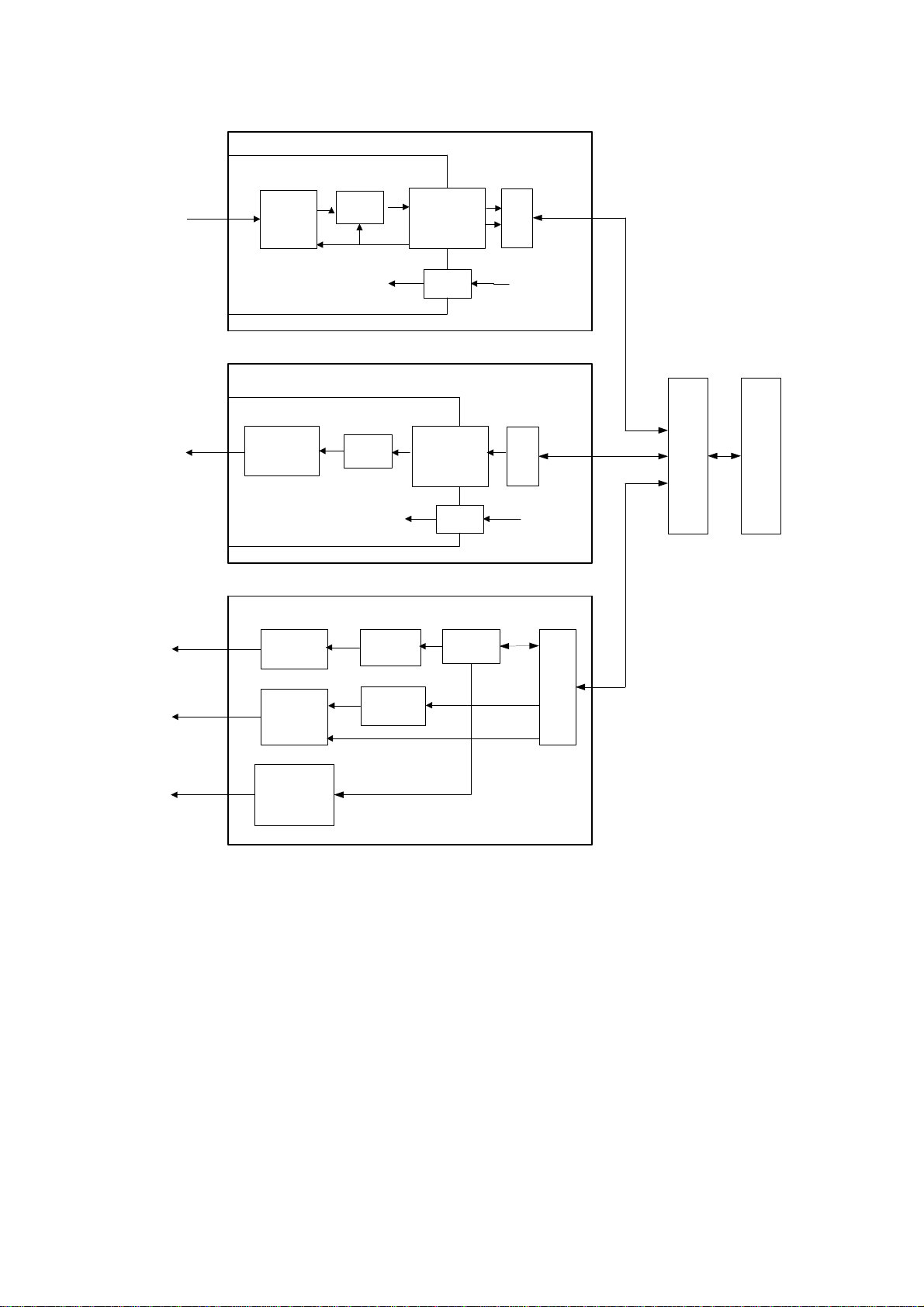
The functional scheme of the digital system is represented on Fig. 1.
Amplifiers MC
SU
Current driver DAC Galvanic
isolation 4000 V
SU
MC
Auditory
amplifier
Switches
Visual amplifier
DAC DSP
PWM
MC
Amplifier unit
Galvanically isolated amplifier module
To electrodes of
biopotentials
Control
Power
supply +5 V from USB
Electrical stimulator unit
Galvanically isolated module of electrical
stimulator
To stimulating
electrodes
Power
supply +5 Вот USB
To auditory
stimulator
To photic stimulator
To visual stimulator
Auditory-visual stimulator unit
USB
HUB PC
USB
USB
USB
Galvanic
isolation 4000 V
DAC
Fig. 1. The functional scheme of the digital system.
The function of the amplification and recording of the biopotentials is performed by the
amplifier unit.
The biopotentials from the electrodes are delivered to the amplifiers of the amplifier
unit where they are amplified, then quantized with the use of the analog-digital con-
verter (ADC) and are transferred to the microcontroller (MC) via 4000 V galvanic isola-
tion. The microcontroller provides the connection with the computer via USB and the
transfer of the digitized data to the computer (PC). Besides, it controls the amplifiers
and ADC operation via 4000 V galvanic isolation.
The power supply of the galvanically isolated part of the amplifier unit, i.e. amplifier
module is done via the galvanically isolated direct-voltage transducer of the supply
unit (SU).

Neuro-MEP, Neuro-ERG (Technical Manual)
18
The function of the electrical stimulation is performed by the electrical stimulator unit.
The microcontroller of the unit provides the connection with the computer via USB and
generates the signal in the discrete form and supplies it to the digital-analog converter
(DAC) via 4000 V galvanic isolation. The DAC transforms it to the analog form and the
current driver generates the current pulse according to the specified form. The power
supply of the galvanically isolated part of the electrical stimulator, i.e. electrical stimu-
lator module is done via the galvanically isolated direct-voltage transducer of the sup-
ply unit (SU).
The functions of the auditory, photic and visual stimulation are performed by the elec-
trical stimulator unit.
The microcontroller of the unit provides the connection between the digital signal pro-
cessor (DSP) of the module and the computer via USB. Also, the MC generates the
amplitude with the use of the pulse-wide modulator (PWM) and the pulse duration on
the photic stimulator with the use of the switches. DSP generates the signal of the
sound stimulator in a discrete form, which is transformed by the digital-analog con-
verter to the analog form, amplified by the sound amplifier and is supplied to the audi-
tory stimulator. DSP also generates the visual signal which is transferred to the visual
stimulator via the visual amplifier.
The photic stimulator is LED goggles with the set of the super-power LEDs for the
separate stimulation of the left and right eye. The headphones can be used as an au-
ditory stimulator and the video monitor as a visual stimulator.
All the three units are attached to the computer via USB hub.
The digital system operates under control of PC (IBM PC type) with the mouse, key-
board, laser or jet printer and installed licensed Windows operational system. Signal
processing, displaying and presentation in different modes after mathematical analy-
sis, then storing of the initial data on the hard disk, exam report generation and print-
ing is done using PC.
Description and Operation
19
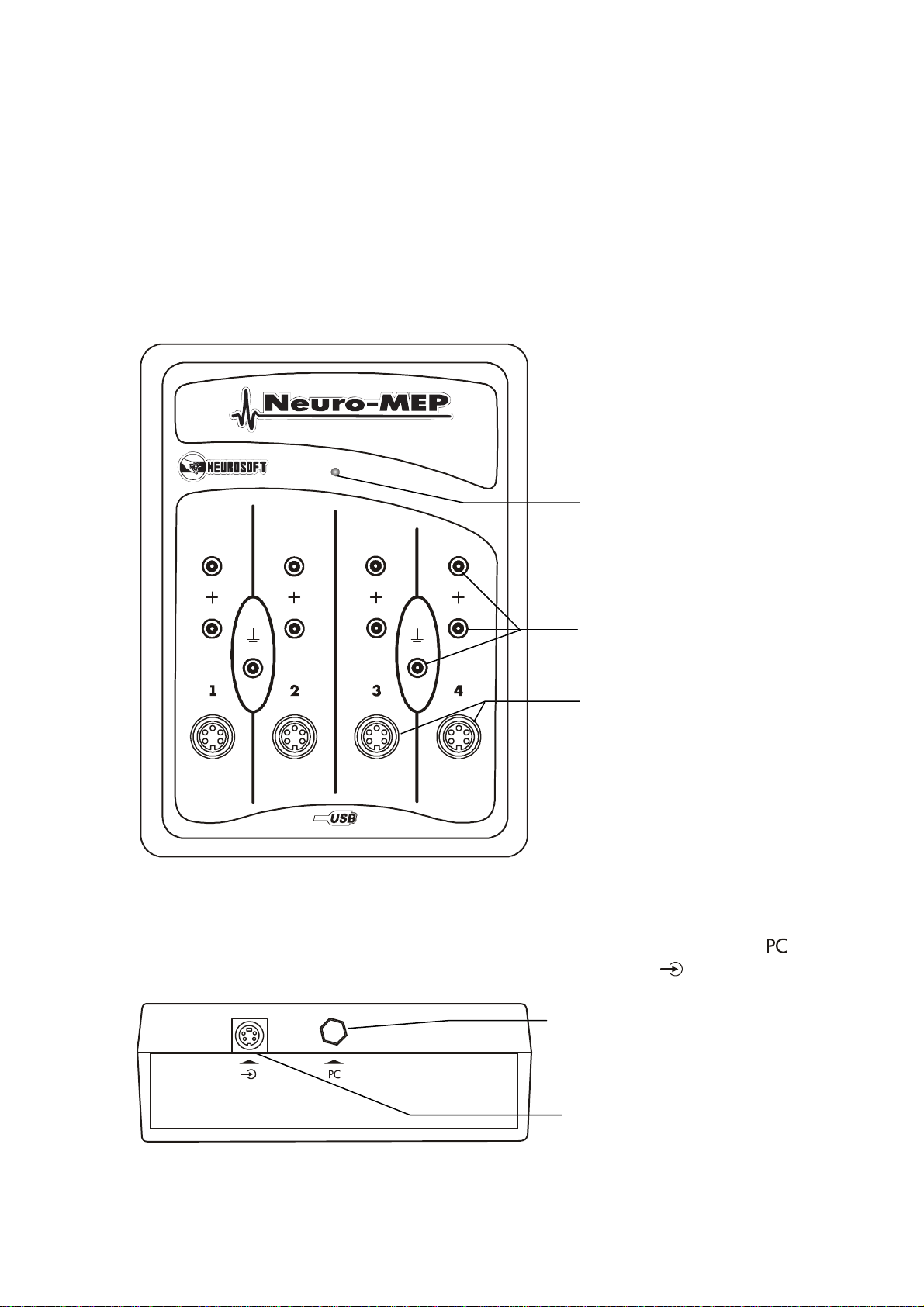
1.5. Connectors and Indicators Function
The external views of the front and side panels of the amplifier unit are represented on
the Fig. 2 and Fig. 3.
The front panel of the amplifier unit contains touchproof and DIN connectors to attach
the electrodes and LED operation indicator (Fig. 2). The channel numbers are marked
with Arabic figures “1”, “2”, “3” and “4”. The operation indicator glows yellow if the unit
is connected to the computer and glows green at the signal recording during the pro-
gram operation.
Fig. 2. The front panel of amplifier unit.
The top side panel of the amplifier unit contains USB cable to connect to computer
and trigger input socket to connect the stimulators of third-party firms (Fig. 3).
Fig. 3
.
The side panel of the amplifier unit.
Touchproof
connectors
DIN
connectors
Operation indicator
USB cable to connect to
computer
Trigger input socket
Neuro-MEP, Neuro-ERG (Technical Manual)
20
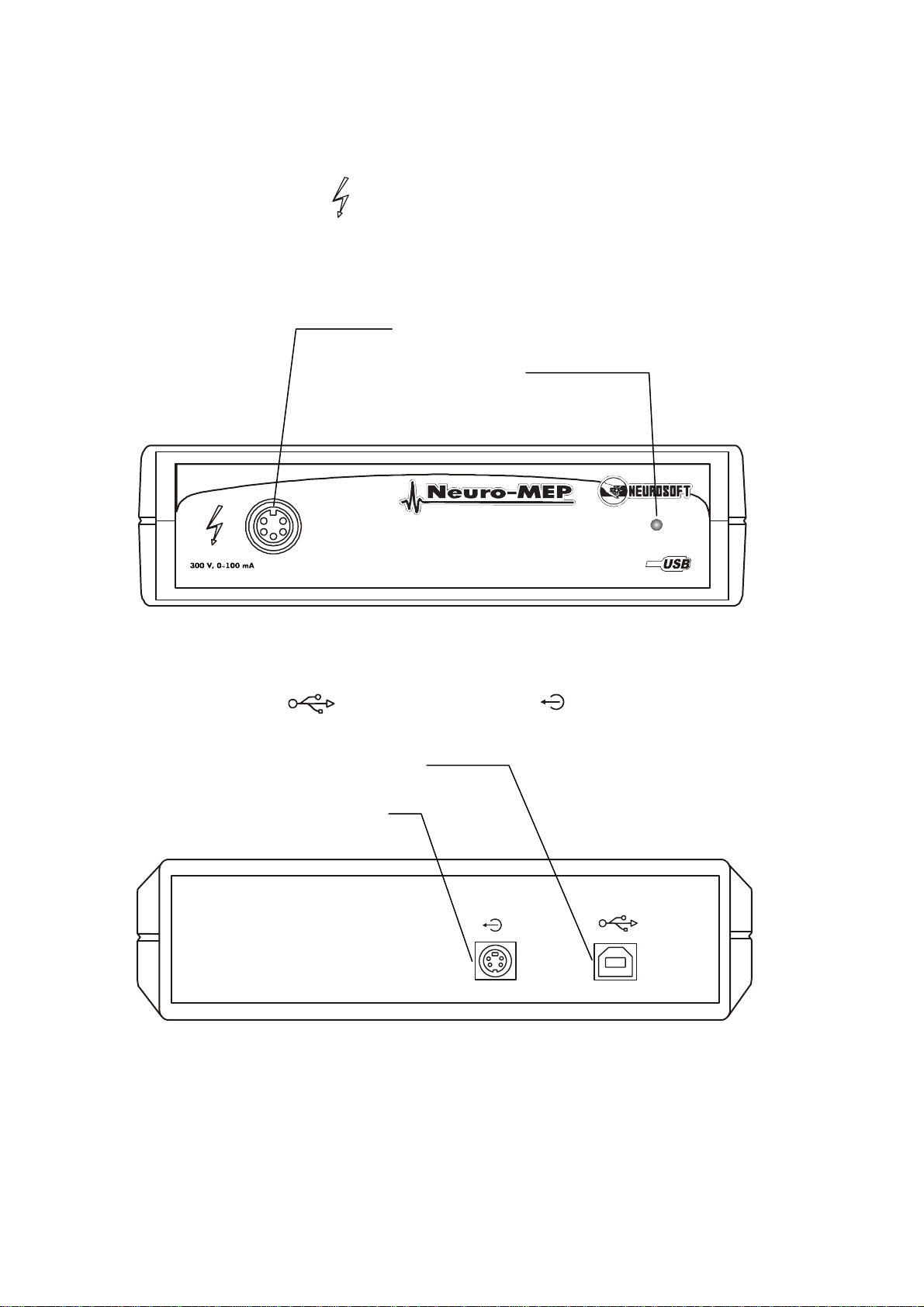
The external views of the front and rear panels of the electrical stimulator are repre-
sented on the Fig. 4 and Fig. 5.
The front panel of the electrical stimulator unit contains the connector for the stimulat-
ing electrode attachment and LED operation indicator (Fig. 4). The operation indi-
cator highlights yellow at the electronic unit connection to computer and highlights
green at the signal recording during the program operation in the tests with the electri-
cal stimulation.
Fig. 4
.
The front panel of the electrical stimulator unit.
The rear panel of the electrical stimulator panel contains the USB cable connector (to
attach to computer) and trigger output socket (Fig. 5).
Fig. 5
.
The rear panel of the electrical stimulator unit.
Connector for the stimulating
electrode connection
Operation indicator
Trigger output socket
Connector to attach USB cable
This manual suits for next models
1
Table of contents
Other Neurosoft Diagnostic Equipment manuals


