Neurosoft Neuron-Spectrum-1 User manual

Technical Manual
Neuron
-
Spectrum
-
1
Neuron-Spectrum-2
Neuron-Spectrum-3
Neuron-Spectrum-4
Neuron-Spectrum-4/P
CloudEEG
Digital Neurophysiological Systems
TM015.03.002.000
(24.03.2020)

Neurosoft© 2020
5, Voronin str., Ivanovo, 153032, Russia
P.O. Box 10, Ivanovo, 153000, Russia
Phone: +7 (4932) 24-04-34 Fax: +7 (4932) 24-04-35
E-mail: com@neurosoft.ru Internet: www.neurosoft.ru
The digital systems Neuron-Spectrum-1, Neuron-Spectrum-2, Neuron-Spectrum-3, Neuron-Spectrum-4 and,
Neuron-Spectrum- 4/P, CloudEEG with Neuron-Spectrum.NET software are intended for use as digital
neurophysiological systems intended for recording, processing and display of biopotential signals such as
Electroencephalography (EEG) and long-latency Evoked Potential (EP). Polysomnography (PSG) derives from
Electroencephalography (EEG) by the means of a dedicated software module and dedicated electrodes.
The devices are portable and can register up to 8 (Neuron-Spectrum-1), 16 (Neuron-Spectrum-2), 19 (Neuron-
Spectrum-3), 21 (Neuron-Spectrum-4, Neuron-Spectrum-4/P, CloudEEG) EEG channels, 1 (Neuron-Spectrum-1,
Neuron-Spectrum-2, Neuron-Spectrum-3 and Neuron-Spectrum-4) or up to 4 polygraphic channels (Neuron-
Spectrum-4/P, CloudEEG: ECG, EOG), 1 respiratory channel and 2 direct current channels (Neuron-Spectrum-4/P).
Neuron-Spectrum.NET includes the Evoked potentials averaging function and Quantitative
electroencephalography (qEEG), including specific parameters such as Rhythmicity, FFT power ratio and
amplitude metrics.
The devices do not provide alarms, do not provide automated event marking and do not provide to the user any
diagnostic conclusion about the patient's condition. They are intended for use in the patient care institutions,
diagnostics centers, neurosurgical hospitals, experimental laboratories and sleep laboratories.
The patient group includes all ages and sexes.*
*Safety of use for this age group isconfirmed bythe resultsof clinical data.
Caution: Federal law restricts this device to sale by or on the order of a licensed healthcare practitioner

3
Contents
Introduction...............................................................................................................4
1. Description and Operation................................................................................ 5
1.1. Function........................................................................................................5
1.2. Safety Measures...........................................................................................6
1.3. Specifications ...............................................................................................6
1.4. Delivery Set................................................................................................11
1.5. Technology and Operation..........................................................................17
1.6. Connectors and Indicators..........................................................................18
2. Installation ....................................................................................................... 20
2.1. Requirements to the Personnel Conducting Systems Installation ...............20
2.2. Room Selection and Placement..................................................................20
2.3. Unpacking and Check of Delivery Set.........................................................23
2.4. Connection to Computer.............................................................................23
3. Proper Use .......................................................................................................25
3.1. Safety Measures when Using the Systems.................................................25
3.2. Setting-up Procedures................................................................................26
3.3. Exams Performing Using the Systems........................................................27
3.4. Actions in Emergency.................................................................................28
4. Servicing..........................................................................................................28
4.1. General Requirements................................................................................28
4.2. Servicing.....................................................................................................28
4.3. Conservation ..............................................................................................28
5. Current Repair ................................................................................................. 29
5.1. General Requirements................................................................................29
5.2. EEG, ECG Cables, Adapters and Linkers Repair........................................29
5.3. Computer Interface Cable Repair (USB cable)............................................29
5.4. Auditory Stimulator Repair..........................................................................29
5.5. Photic Stimulator Repair.............................................................................30
5.6. Visual Pattern-Stimulator Adapter Repair....................................................31
6. Packing and Transportation ...........................................................................32
7. Storage Regulations........................................................................................ 32
8. Utilization.........................................................................................................32
9. Delivery Set and Package Data.......................................................................33
10. Acceptance Certificate....................................................................................33
11. Delivery Certificate..........................................................................................33
12. Storage Data ....................................................................................................34
13. Warranty........................................................................................................... 35
14. Reclamation Data ............................................................................................35
15. Repair Data ...................................................................................................... 38
Appendix 1. Electromagnetic Emissions and Immunity ......................................39
Appendix 2. Trigger Input/Output.......................................................................... 43

Neuron-Spectrum (Technical Manual)
4
Introduction
This technical manual (hereinafter referred to as “the manual”) is the combined
document describing operation and servicing of digital neurophysiological systems
Neuron-Spectrum-1,Neuron-Spectrum-2,Neuron-Spectrum-3,Neuron-
Spectrum-4,Neuron-Spectrum-4/P and CloudEEG (hereinafter referred to as
“the systems”).
The document certifies technical parameters of digital EEG systems, which are
guaranteed by the manufacturer.
Do not start working with the systems before you have read this manual!
Because of the continuous improvements of the digital EEG systems, its construction
could be modified. These modifications do not degrade the digital EEG system
performance and could be not described in this manual.
You can send your responses and recommendations to the following address:
P.O. Box 10,Ivanovo,153000,Russia
or by e-mail:
You can find additional information on Neurosoft products on our website:
www.neurosoft.com
or ask questions by phone:
+7 (4932) 59-21-12 (Service Center)
+7 (4932) 24-04-34

Description and Operation
5
1. Description and Operation
1.1. Function
The digital EEG systems Neuron-Spectrum-4/P, CloudEEG are intended for EEG,
long-latency EP recording in any unshielded room.
The digital systems Neuron-Spectrum-1, Neuron-Spectrum-2, Neuron-Spectrum-3
and Neuron-Spectrum-4, CloudEEG are produced on the basis of Neuron-
Spectrum-4/P and intended for the recording of EEG and long-latency EP in any
unshielded room.
The devices are portable and can register up to 8 (Neuron-Spectrum-1), 16
(Neuron-Spectrum-2), 19 (Neuron-Spectrum-3), 21 (Neuron-Spectrum-4, Neuron-
Spectrum-4/P, CloudEEG) EEG channels, 1 (Neuron-Spectrum-1, Neuron-
Spectrum-2, Neuron-Spectrum-3 and Neuron-Spectrum-4) or up to 4 (Neuron-
Spectrum-4/P, CloudEEG) polygraphic channels (ECG, EOG), 1 breath channel and 2
direct current channels (Neuron-Spectrum-4/P, CloudEEG).
The systems can be used in the patient care institutions, diagnostics centers,
neurosurgical hospitals and experimental laboratories of the research institutions to:
·Record, review and analyze EEG;
·Record, review and analyze long-latency EP;
·Study polysomnography.
The operation of the device in the video EEG monitoring mode is possible for not
more than 30 days.
The general properties, when carrying out EEG or EP study using EEG channels:
·21-channel EEG/EP recording in any unshielded room;
·Up to 2 direct current channels recording (Neuron-Spectrum-4/P, CloudEEG);
·Photic, auditory stimulation and stimulation carrying out with the use of reversal
checkerboard pattern;
·Synchronous long-term recording of EEG and video from one, two or three video
cameras and recording of audio information from one or two microphones;
·Long-latency EP recording using EEG channels: flash and reversal pattern visual,
auditory and cognitive (P300, MMN, CNV);
·Spectral EEG analysis, exam report generation, export and import of files in the
standard European data format (EDF);

Neuron-Spectrum (Technical Manual)
6
·Review, store and print of the recorded traces, results of their analysis and exam
reports.
A patient stimulation can be performed with the use of stimulators built in the device.
The main condition for using the digital EEG systems is the good professional skills of
the medical staff.
1.2. Safety Measures
To ensure the safety and exclude the hazard of medical staff’s or patient’s
electric shock, the medical staff is PROHIBITED:
·to use the digital EEG system which was mounted and installed incorrectly, without
following this manual instructions;
·to connect digital EEG system and other high-frequency equipment to patient (it can
lead to burns in places of electrode attachment or system damage);
·to connect another equipment (not included in delivery set) to electrode slots;
·to open the units to make repair;
·to work with the digital EEG system when the electronic unit, computer or other
devices used together with the stimulator are opened;
·to connect electrodes placed on the patient to protective ground or other
conducting surfaces.
1.3. Specifications
Table 1. Main Specifications
Parameters
Values
EEG Channels
Number of channels 8/16/19/21*
Sampling rate 100, 200, 500, 1000, 2000,
5000 Hz
Input range 1–12000 µV
Ratio error of voltage measurement:
·in the range from 10 up to 50 µV
·in the range from 51 up to 12000 µV within ±15%
within ±5%
Ratio error of time interval measurement in the range from
10 µs up to 10 s within ±2%

Description and Operation
7
Table 1. Continued
Parameters
Values
Sensitivity 1–1000 µV/mm
(step 1 µV/mm)
Ratio error of sensitivity within ±5%
Sweep speed at EEG recording 3–960 mm/s (step 1 mm/s)
Sweep speed at EP recording 5, 10, 20, 50, 100, 200,
500 ms/div.
Ratio error of sweep speed within ±2%
High pass filter 0.05–10 Hz (step 0.01 Hz)
Low pass filter 5–200 Hz (step 0.1 Hz)
Bandpass flatness in range from 0.5 up to 60 Hz from –10 up to +5%
Suppression ratio of power frequency by notch filter not less than 40 dB
Common-mode rejection not less than 110 dB
Input noise level within 0.5-200 Hz (rms value) not more than 2 µV
(not more than 0.3 µV)
Input impedance not less than 400 MΩ
Patient leakage current not more than 50 nA
Polygraphic Channels
Number of channels 1/4**
Input range 0.2–100 mV
Ratio error of voltage measurement in the range:
·from 200 up to 500 µV
·from 0.5 up to 100 mV within ±15%
within ±7%
Sensitivity 0.001, 0.002, 0.005, 0.007,
0.01, 0.02, 0.05, 0.07, 0.1,
0.2, 0.5 mV/mm
High pass filter 0.05, 0.1, 0.2, 0.5, 0.7, 1.5, 2,
5, 10 Hz
Low pass filter 5, 10, 15, 35, 75, 100, 150,
200 Hz
Bandpass flatness in the range:
·from 0.5 up to 200 Hz
·from 0.05 up to 0.5 Hz and from 200 up to 250 Hz from –10 up to +5%
from –30 up to +5%
Suppression ratio of power frequency by notch filter not less than 40 dB
Input noise level within 0.05-200 Hz not more than 3 µV
Input impedance not less than 400 MΩ
Patient leakage current not more than 50 nA
Common mode rejection not less than 100 dB

Neuron-Spectrum (Technical Manual)
8
Table 1. Continued
Parameters
Values
Direct Current Channels***
Number of channels 2
Input range from –3 V up to +3 V
Ratio error of voltage measurement in the range:
·from 0.3 mV up to 1 mV
·from 1 mV up to 3 V within ±15%
within ±7%
Sensitivity 1, 2, 5, 7, 10, 20, 50, 70, 100,
200, 500 mV/mm
Ratio error of sensitivity within ±5%
Input impedance not less than 100 MΩ
Cutoff frequency (–3 ± 0.5 dB) 200 Hz
Photic Stimulator
Number of channels 1
Stimulus duration 0.1–3000 ms
Relative deviation of stimulus duration within ±10%
Maximal brightness of LED stimulator (FS-1) (16000 ± 1600) cd/m
2
Stimulation frequency 0.1–100 Hz
Relative deviation of stimulation frequency within ±1%
Left/right/two-sided stimulation yes
Auditory Stimulator
Number of channels 2 (right and left)
Stimulation level: 0–126 dB SPL (TDH-39)
Stimulation frequency 0.1–100 Hz
Relative deviation of stimulation frequency within ±1%
Stimulus duration 100–5000 µs
Relative deviation of stimulus duration within ±15%
Left/right/double-sided stimulation yes
Compression/depression yes
Pattern
-
stimulator
Stimulation frequency 0.1–10 Hz
Relative deviation of stimulation frequency within ±10%
Pattern size 4´3, 8´6, 16´12, 32´24,
64´48 sqr.

Description and Operation
9
Table 1. Continued
Parameters
Values
Breath Channel
Number of channels 1
Breath frequency range 6–30 inhalations per minute
Breath channel bandpass 0.05–7.5 Hz
General Specifications and Parameters
Interface USB
Supply voltage:
·electronic unit
·desktop PC-based system
·notebook PC-based system
5 V DC
220/230 V AC (50 Hz)
220/230 V AC (50 Hz) / int.
battery
Electronic unit power consumption not more than 2.8 V´A
Electronic unit dimensions 140´200´45 mm
Electronic unit weight not more than 0.9 kg
Delivery set weight (without computer and printer) not more than 12.5 kg
Safety BF type
Notes:
*number of channels for Neuron-Spectrum-1 (8), Neuron-Spectrum-2 (16), Neuron-
Spectrum-3 (19), Neuron-Spectrum-4 and Neuron-Spectrum-4/P, CloudEEG (21)
correspondingly.
** number of polygraphic channels for Neuron-Spectrum-1 (1), Neuron-Spectrum-2 (1),
Neuron-Spectrum-3 (1), Neuron-Spectrum-4 (1) and Neuron-Spectrum-4/P,CloudEEG (4)
correspondingly.
*** for Neuron-Spectrum-4/P, CloudEEG.

Neuron-Spectrum (Technical Manual)
10
Safety and Electromagnetic Compatibility
Electromagnetic compatibility (EMC) is provided by IEC 60601-1-2:2007 requirements
fulfillment.
The devices are intended for operation in electromagnetic environment, which special
features are specified in Appendix 1.
Portable and mobile RF communication equipment can affect the system operation.
The use of the equipment not listed in tables 2 - 6 of the present technical manual
may result in increased emission and system decreased immunity.
As for safety, each digital EEG system satisfies IEC 60601-
1:1988+A1:1991+A2:1995, IEC 60601-1-1:2000 and IEC 60601-2-26:2002. The
electronic units of digital EEG systems are supplied by regulated power supply
through USB interface, it has double isolation and BF type work parts according to
IEC 60601-1.
Interpretation of symbols on the electronic EEG unit:
-
Attention: consult user and technical manuals.
-
Work parts of BF type according to IEC 60601-1.
-Mark of conformance to Russian standards requirements.
-
Mark of measuring device conformance to Russian standards
requirements.
-
Mark of conformance to 93/42/EEC “Concerning Medical Devices”
directive.
-
Mark of conformance to 2002/96/EC “On waste electrical and electronic
equipment (WEEE)” directive.

Description and Operation
11
1.4. Delivery Set
Neuron-Spectrum digital EEG systems include a unit with different accessories sets
for channels of EEG, polygraphic and software which can be delivered to the
customer both jointly and separately, and also components and bought articles. The
delivery set depends on the digital EEG system configuration and corresponds to
Table 2 and Table 3.
Designations in tables 2 and 3:
·1 – Neuron-Spectrum-1 digital EEG system;
·2 – Neuron-Spectrum-2 digital EEG system;
·3 – Neuron-Spectrum-3 digital EEG system;
·4 – Neuron-Spectrum-4 digital EEG system;
·5 – Neuron-Spectrum-4/P digital EEG system;
·6 – CloudEEG digital EEG system
Table 2. Base Delivery Set
Name
Document code of main
specifications
Quantity per configurat
ion
,
pcs
.
1
2
3
4
5
6
Neuron
-
Spectrum
-
1
electronic unit 1) NS015201.028
NS015201.028-001 1− − − −-
Neuron
-
Spectrum
-
2
electronic unit 1) NS015201.029
NS015201.029-001 −1− − −-
Neuron
-
Spectrum
-
3
electronic unit 1) NS015201.030
NS015201.030-001 −−1−−-
Neuron
-
Spectrum
-
4
electronic unit 1) NS015201.031
NS015201.031-001 −−−1−-
Neuro
n
-
Spectrum
-
4/P
electronic unit 1) NS015201.033
NS015201.033-001 − − − − 1 -
CloudEEG
electronic unit
NS015201.045-028
NS015201.045-029 − − − − −1
Stand NS016998.007
(SH–3) −1 1 1 1 1
Holder for SN-3 stand NS016221.009 −1 1 1 1 1
Assembled holder NS016201.038 (H-1) 1 − − − −-
Holder fastener NS006200.002 1 − − − −-
LED photic stimulator NS005302.005
(PS-1) −1 1 1 1 1
Stand for electronic unit NS016201.042 (SU-9) −1 1 1 1 1
LED photic stimulator on
holder NS012302.005
(PS-3) 1− − − −-

Neuron-Spectrum (Technical Manual)
12
Table 2. Continued
Name
Document code of
main specifications
Quantity per configuration, pcs.
1
2
3
4
5
6
Accessories for EEG Acquisition
:
EEG/EP Cup electrode
1)
Ambu Inc. 12 20 23 25 25 25
Pastes:
Electrode adhesive paste
1
)
Ten20, 114 g (USA) 1 1 1 1 1 1
Operational Documentation:
Neuron
-
Spectrum
technical
manual TM015.03.002.000 1 1 1 1 1 1
Neuron
-
Spectrum.NET
user
manual UM015.04.002.001 1 1 1 1 1 1
Exams Manager
appendix to
user manual AU999.01.005.000 1 1 1 1 1 1
Software on CD
:
Neuron
-
Spectrum.NET
software without additional
modules 1 1 1 1 1 1
Package
:
Cardboard package (set) 002901.001 1 1 1 1 1 1
Notes:
1) The accessories and consumables of analogous types can be used if their application is
permitted in the country.
Table 3. Optional Equipment, Accessories and Software
Name
Document code or
main specifications
Quantity per configuration, pcs.
1
2
3
4
5
6
Auditory stimulator
(headphones) NS032305.005
(TDH-39) 1 1 1 1 1 1
Ultima Airflow Sensor
3)
Braebon Medical
Corporation 1 1 1 1 1 1
USB extension cable Omix 20 m (UniqueICs,
Russia) 1 1 1 1 1 1
USB hub
1)
NS042999.002 1 1 1 1 1 1

Description and Operation
13
Table 3. Continued
Name
Document code or
main specifications
Quantity per configuration, pcs.
1
2
3
4
5
6
Neuron
-
Spectrum
-
PSG
equipment see table 4 1 1 1 1 1 1
Neuron
-
Spectrum
-
Video
equipment see table 5 1 1 1 1 1 1
Accessories for EEG Acquisition:
Disposable needle electrode
3
) Technomed Europe 12 20 23 25 25 25
Electrode cap for 19-channel
EEG recording 3) ELECTRO-CAP
(Electro-CAP, USA)
46-50 (XSM), 50-54
(SM),
54-58 (M), 58-62 (L),
34-38, 38-42, 42-46
(pediatric)
1 1 1 1 1 1
Strap for electrode cap
3
)
ELECTRO-CAP
(Electro-CAP, USA)
46-50 (XSM), 50-54
(SM),
54-58 (M), 58-62 (L),
(pediatric)
1 1 1 1 1 1
Electrode cap extension cable NS007103.023-30 1 1 1 1 1 1
Special needle for filling
electrodes with gel3) ELECTRO-CAP
(Electro-CAP, USA) 1 1 1 1 1 1
Ear electrode (pair) for
electrode cap 3) ELECTRO-CAP
(Electro-CAP, USA) 1 1 1 1 1 1
EEG/EP Cup electrode
2)
Ambu Inc. 12 20 23 25 25 25
Pastes:
Electrode adhesive paste
2
)
Ten20, 114 g (USA) 1 1 1 1 1 1
Neuron
-
Spectrum
-
LEP
Equipment
:
Auditory stimulator
(headphones) NS032305.005 (TDH-
39) 1 1 1 1 1 1
Adapter for pattern-stimulator
connection NS033201.005 1 1 1 1 1 1
Adapter for high resolution
pattern-stimulator
connection 3)
NS033201.003 1 1 1 1 1 1

Neuron-Spectrum (Technical Manual)
14
Table 3. Continued
Name
Document code or
main specifications
Quantity per configuration, pcs.
1
2
3
4
5
6
Accessories for ECG
Acquisition
:
INTCO Tab Electrode
2
)
Shanghai lntco Electrode
Manufacturing Co., Ltd. 3 3 3 3 3 3
Cable for one ECG channel
(set – 3 pieces) NS005103.003
NS007103.016 1 1 1 1 1 1
Software on CD
:
Neuron
-
Spectrum.NET
software
with
Neuron
-
Spectrum.NET/LEP
additional module
1 1 1 1 1 1
with
Neuron
-
Spectrum.NET/PSG
additional module
1 1 1 1 1 1
with
Neuron
-
Spectrum.NET/Video
additional module
1 1 1 1 1 1
Electronic Equipment
Isolation transformer
4)
NS036999.001
(TM-630M) 1 1 1 1 1 1
Notes:
1) Connect USB devices through the KM-7 USB hub if you use several USB devices.
2) Components which are not included into Neuron-Spectrum-LEP base delivery set.
3) The accessories and consumables of analogous types can be used if their application is
permitted in the country.
4) The delivery of another transformer with similar input and output characteristics certified
according to IEC 60601-1 is permitted.

Description and Operation
15
Table 4. Neuron-Spectrum-PSG Delivery Set
Name Document code and main
specifications Quantity,
pcs.
EEG/EP Cup electrode
1)
Ambu Inc. 9
Ultima Airflow Sensor
1)
Braebon Medical Corporation 1
Ultima Respiratory Effort Sensor
1)
Braebon Medical Corporation 1
Reusable Airflow/Snore Sensor
1)
Dymedix Inc 1
Ultima Body position sensor
1)
Braebon Medical Corporation 1
Video camera CNB-ZBN-21Z27F
(CNB Technology Inc,Korea) 1
Power supply unit GS25E-12P1J (Mean Well
Enterprises Co., Taiwan) 2
Splitter cable NS015103.036 1
Video cable NS015103.013 1
Tripod for video camera HAMA 04127 Star27 3D,
63-152 sm 1
Remote control CNB-SC100 1
Control cable for video camera NS015103.032 1
USB extension cable Omix 20 m (UniqueICs Ltd, Russia) 1
Extension cable NS015103.035 1
IR projector NS015302.004 1
Patient microphone NS015355.003 1
Bracket for patient’s microphone NS015221.007 1
Bracket SAB-03 (N) (Orient, Russia) 1
PCI video capture card USB 1
USB hub NS042999.002 1
Medical tape
1)
Article 1527-2, Transpore (3M
Company, 3M Health Care, USA) 1
Electrode adhesive paste
1)
TEN20, 114 g (USA) 1
Operational Documentation
Neuron
-
Spectrum
technical manual
2
)
TM015.03.002.000 1
Package
:
Transportation bag - 1
Notes:
1) The accessories and consumables of analogous types can be used if their application is
permitted in the country.
2) In case you purchase the digital system with the EEG system manufactured by
Neurosoft Ltd. these positions are not included in the delivery set.

Neuron-Spectrum (Technical Manual)
16
Table 5. Neuron-Spectrum-Video Delivery Set
Name Document code and main
specifications Quantity,
pcs.
Video camera CNB-ZBN-21Z27F
(CNB Technology Inc, Korea) 1
Power supply unit GS25E-12P1J (Mean Well
Enterprises Co., Taiwan) 2
Adapter for power supply unit NS015103.036 1
Video cable NS015103.013 1
Video camera tripod HAMA 04127 Star27 3D,
63-152 cm (Germany) 1
Bracket SAB-03 (N)
(Orient, Russia) 1
Remote control CNB-SC100
(CNB Technology Inc, Korea) 1
Control cable for video camera NS015103.032 1
Video capture card USB 1
Patient’s microphone NS015355.003 1
IR projector NS015302.004 1
Electrode cap for 19-channel
EEG recording 1) ELECTRO-CAP
(Electro-CAP, USA)
46-50 (XSM), 50-54 (SM),
54-58 (M), 58-62 (L),
34-38, 38-42, 42-46 (pediatric)
1
Strap for electrode cap
1
)
ELECTRO-CAP
(Electro-CAP, USA)
46-50 (XSM), 50-54 (SM),
54-58 (M), 58-62 (L),
(pediatric)
1
Special needle for filling electrodes with
gel1) ELECTRO-CAP
(Electro-CAP, USA) 1
Ear electrode (pair) for electrode cap
1)
ELECTRO-CAP
(Electro-CAP, USA) 1
USB extension cable Omix 20 m
(UniqueICs Ltd, Russia) 1
Extension cable NS015103.035 1
USB hub TC 4083-042-13218158-2006
NS042999.002 1
Notes:
1) The accessories and consumables of analogous types can be used if their application is
permitted in the country.
Description and Operation
17
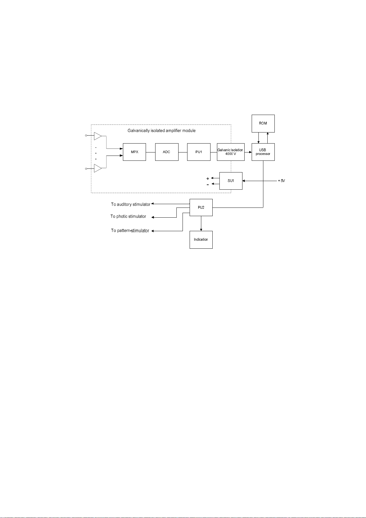
1.5. Technology and Operation
Digital EEG system mode of operation is based on the acquisition and input of brain
biopotentials and other physiological signals into PC for the analysis of brain electrical
activity taking into account the influence of the other physiological signals.
The functional circuit of the digital EEG system is shown in Fig. 1.
To electrodes of biopotentials
recording, breath sensor, DC
channels
Fig. 1. The functional diagram of the digital EEG system.
EEG, ECG, breath and direct current DC1, DC2 biopotentials are amplified, digitized
in turn by means of analog-digital converter (ADC) and multiplexer (MPX) under the
control of the processor PU1, they are transmitted to USB processor through the
optrons of galvanic isolation.
The processor PU1 of amplifier module controls measurement, calibration, impedance
measurement and internal diagnostics modes.
The power supply of the amplifier module is performed through electrically isolated
DC converter (SU1).
The processor PU2 controls audio stimulus level, duration, frequency and polarity. It
controls the stimulus duration of photic stimulator and generates commands to pattern
stimulator via the signal generators G1, G2, G3.
All the processors receive commands and transmit data through USB processor which
forms data packets to transmit them to computer and deciphers data transmitted from
computer to control the modules.
Digital EEG system operates under control of PC (IBM PC type) with the mouse, key-
board, laser or ink jet printer and installed licensed Windows XP/Vista/7/8 operational
system.
Signal processing, displaying and presentation in different modes after mathematical
analysis, storing of the EEG traces on the hard disc, exam report generation and their
printing is done with the use of PC.

Neuron-Spectrum (Technical Manual)
18
1.6. Connectors and Indicators
The external view of front and side panels of the amplifier unit is represented on
Fig. 2, Fig. 3 and Fig. 4.
Touch-proof connectors for electrode cables attachment, LED operation indicator and
impedance indicators are located on the front panel (Fig. 2).
Fig. 2. The external view of the front panel.
EEG channels are marked as “FP1…O2”, “A1”, “A2”, polygraphic channels are
marked as “1”, “2”, “3”, “4”. The slot is used to attach the ground electrode.
The operation indicator glows yellow at the electronic unit connection to the computer,
glows green at the signal acquisition during the program operation.
The color of impedance indicator highlighting shows the quality of electrode
placement: the green color indicates the good quality of electrodes placement, the
yellow color is the mean one, the red color is the bad one. The borders of electrode
placement quality differentiation by colors are software-set.

Description and Operation
19
The top side panel of the amplifier unit contains the connectors for two direct current
channels attachment, the connector for breath sensor attachment, USB cable for the
attachment to computer, the trigger socket (trig-in/trig-out) to attach the stimulators of
other manufacturers, the connector for pattern-stimulator adapter attachment, the
connector for visual stimulator attachment, the connector for the auditory stimulator
attachment (Fig. 3).
Fig. 3. The external view of the top side panel.
The bottom side panel contains the connector for electrode cap attachment (Fig. 4).
Fig. 4. The external view of the bottom side panel.
DC2 direct current channel
DC1 direct current channel
Trigger socket (trig-in/trig-out)
Connector for pattern-stimulator adaptor
attachment
Connector for visual stimulator
connection
Connector for auditory
stimulator attachment
Connector for breath sensor attachment
USB cable
Connector for electrode cap attachment

Neuron-Spectrum (Technical Manual)
20
2. Installation
2.1. Requirements to the Personnel Conducting
Systems Installation
Digital EEG system installation should be carried out by the person who is
empowered by the manufacturer or the technical personnel of the medical institution
which is going to use it. It is necessary to remember that digital EEG system mounting
accuracy defines safety and quality of operation. Further mounting and setting
requirements which define the product safety will be marked by bold and italic fonts
in the text.
2.2. Room Selection and Placement
Before mounting and setting of digital EEG system, it is necessary to select a place
for it, taking into consideration power wiring and protective ground in the room.
Please, read and respect the following requirements and recommendations:
Requirements concerning the room selection and equipment placement:
·The recommended distance from the electronic unit to the nearest electric mains is
not less than 3 meters.
·Do not place the electronic unit in the immediate vicinity (less than 5 meters) to
short-wave or microwave therapeutic equipment (it can lead to its unstable
operation).
·Place the electronic unit at the maximum possible distance from power cables,
switchboards, and different powerful electrical devices which can emit
electromagnetic fields of mains frequency.
·The patient environment (within 1.5 meters) should contain only the
electronic units being the medical devices with the required safety level. The
fact is that the safety level of the computer equipment is insufficient for the
use in the patient environment. Hence, a patient must not contact with the
metal parts of computer equipment cases and the personnel must not touch
simultaneously these parts and patient body. The computer equipment used
in the system should correspond to IEC 60601-1 or be connected via the
isolation transformer (specialized power supply unit – for notebook PC)
corresponding to above-mentioned requirements.
Requirements to mains:
·Do not use electric mains where the neutral conductor and protective ground
are combined. It is strongly prohibited.
This manual suits for next models
5
Table of contents
Other Neurosoft Diagnostic Equipment manuals


