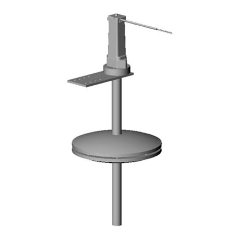
Neutronics QUICK DETECT User manual

QUICK DETECT™
A/C SEALANT DETECTION KIT
OPERATION MANUAL
Manual Part Number: 5-06-7000-62-0
Manual File MN-A-0001 Rev. E
8
9
10
3
4
5
6
7
1
2
Flow
456 Creamery Way, Exton, PA 19341
www.neutronicsinc.com


Manual Part Number:
5-06-7000-62-0
Manual File:
MN-A-0001 Rev. E
Revision Date:
J
une 5, 2006 Page iii
Table of Contents
TABLE OF CONTENTS ...............................................................................................................................................III
FOR YOUR SAFETY: ....................................................................................................................................................V
WELCOME ..................................................................................................................................................................VI
1COMPONENT IDENTIFICATION ......................................................................................................... 1-1
1.1 TEST RIG ........................................................................................................................................................1-1
1.2 FLOW METER ASSEMBLY ................................................................................................................................1-1
1.3 SYRINGE ASSEMBLY........................................................................................................................................1-1
1.4 SENSING PLUG &SAFETY CAP ........................................................................................................................1-1
1.5 ADDITIONAL ITEMS..........................................................................................................................................1-2
2ASSEMBLING THE QUICK DETECT ................................................................................................... 2-3
2.1 FIRST USE ......................................................................................................................................................2-3
2.2 STEP 1–PREPARING THE SENSING PLUG........................................................................................................2-3
2.3 STEP 2–INSERTING THE SENSING PLUG .........................................................................................................2-3
2.4 STEP 3–INSTALLING THE SAFETY CAP............................................................................................................2-3
2.5 STEP 4–ATTACHING THE HOSE.......................................................................................................................2-4
2.6 STEP 5–ATTACHING THE FLOW METER ...........................................................................................................2-4
3TESTING FOR SEALANT .................................................................................................................... 3-5
3.1 PREPARING THE VEHICLE ................................................................................................................................3-5
3.2 TESTING THE VEHICLE WITH THE ENGINE OFF ...................................................................................................3-5
3.3 TESTING THE VEHICLE WITH THE ENGINE ON....................................................................................................3-5
3.4 MONITORING THE TEST....................................................................................................................................3-6
3.5 CHECKING THE TEST RESULTS .........................................................................................................................3-6
3.6 CLEANING THE SYSTEM ...................................................................................................................................3-6

4APPENDICES.......................................................................................................................................4-7
4.1 APPENDIX A-SPARE PARTS LIST ...................................................................................................................4-7
4.2 APPENDIX B-SPECIFICATIONS........................................................................................................................4-7
4.3 APPENDIX C-TROUBLESHOOTING ...................................................................................................................4-7
4.3.1 Low Flow Readings...................................................................................................................4-7
4.3.2 No High Side Service Port.........................................................................................................4-7
4.4 APPENDIX D–INTENDED USE .........................................................................................................................4-7
4.5 APPENDIX E-WARRANTY............................................................................................................................4-8
Manual Part Number:
5-06-7000-62-0
Manual File:
MN-A-0001 Rev. E
Revision Date:
J
une 5, 2006 Page iv

For Your Safety:
PLEASE READ THIS MANUAL IN ITS ENTIRETY BEFORE ATTEMPTING
INSTALLATION OR OPERATION! Attempting to operate the Ultima ID without
fully understanding its features and functions may result in unsafe conditions
TEST RIGS MAY CONTAIN LIQUID REFRIGERANT UNDER PRESSURE. Contact with
refrigerant may cause injury. Wear protective equipment, including safety goggles. Disconnect
test rig from A/C system with extreme caution.
CAUTION: RISK OF INJURY. THIS EQUIPMENT SHOULD BE OPERATED ONLY BY CERTIFIED
PERSONNEL. Operator must be familiar with A/C systems and refrigerant and dangers of
pressurized components.
Avoid breathing A/C refrigerant and lubrication vapor or mist. Exposure may irritate eyes,
nose and throat. Additional health and safety information may be obtained from refrigerant
and lubrication manufacturers.
Use this equipment in locations with mechanical ventilation that provides at least four air changes per
hour.
DO NOT OPERATE EQUIPMENT UNATTENDED. Equipment requires constant observation of
flow rate for the time period specified in procedure. Unattended operation may result in
excessive refrigerant discharge to the environment.
VERIFY SENSING PLUG CONNECTION INTO TEST RIG PRIOR TO TESTING. Incomplete
connection of sensing plug into coupler of test rig will result in sudden ejection from test rig
when connected to A/C system.
USE ONLY ORDINARY CLEAN TAP WATER IN THE WETTING OF SENSING PLUGS. Dirty
water or other fluid types may cause false indications of sealant presence.
DO NOT REMOVE SENSING PLUGS FROM SHIPPING BAGS UNTIL READY FOR USE. The
sensing plugs are sensitive to fouling from dirt, liquid, etc.
USE ONLY REPLACEMENT PARTS SUPPLIED BY NEUTRONICS INC. Use of non-authorized
replacement parts will void all warranties and may result in false or erroneous test results.
DO NOT UTILIZE QUICK DETECT SYSTEM WITHOUT SAFETY SHIELD. Use of system without
safety shield may result in accidental release of refrigerant charges.
DO NOT POSITION FLOWMETER BELOW LEVEL OF TEST PORT. Positioning of the flowmeter
below the level of the A/C test port may result in flowmeter flooding with liquid refrigerant, oil,
dye and sealant.
Manual Part Number:
5-06-7000-62-0
Manual File:
MN-A-0001 Rev. E
Revision Date:
J
une 5, 2006 Page v

Manual Part Number:
5-06-7000-62-0
Manual File:
MN-A-0001 Rev. E
Revision Date:
J
une 5, 2006 Page vi
WELCOME
Thank you for purchasing the QUICK DETECT A/C Sealant Detector.
The Quick Detect is designed to detect the presence harmful Type II sealants at the High Side service port of
the A/C System. The Quick Detect uses disposable cartridges in conjunction with flow measurement to
determine the presence of active sealant. We recommend that all personnel who use this instrument read
this manual to become more familiar with its proper operation.
For further information regarding the application, operation or spare parts, please contact the Neutronics
Inc. Customer Service Department. If you have questions or comments, we would like to hear from you.
Neutronics Inc.
456 Creamery Way
Exton, PA 19341
Tel: 610) 524-8800
Toll Free: (800) 378-2287 (US only)
Fax: (610) 524-8807
EMAIL: [email protected]
Visit us at www.neutronicsinc.com
Copyright ©2004 Neutronics Inc.
This work is protected under Title 17 of the US Code and is the sole property of Neutronics Inc. No part of this document may
be copied or otherwise reproduced, or stored in any electronic information retrieval system, except as specifically permitted
under US copyright law, without the prior written consent of Neutronics Inc.

Component Identification
1COMPONENT IDENTIFICATION
1.1
si
Test Rig
Provides connection of sensing plug to the high
based A/C systems.
de or liquid service port of R134a or R12
1.2
Provides visu
Flow Meter Assembly
al indication of refrigerant leak flow rate.
1
2
3
4
5
1
2
3
4
5
1.3
Provides
Syringe Assembly
method for injection of water into sensing plugs ends
8
9
10
3
4
5
6
7
1
2
1.4
Sensing Plug ant detection function of
refriger
Sensing Plug & Safety Cap
provides seal
ant from test rig.
. Safety cap prevents accidental release
R134a Test Ri
g
R12 Test Ri
g
Sensing Plug (10) Safety Cap
Manual Part Number:
5-06-7000-62-0
Manual File:
MN-A-0001 Rev. E
Revision Date:
J
une 5, 2006 Page 1-1

Manual Part Number:
5-06-7000-62-0
Manual File:
MN-A-0001 Rev. E
Revision Date:
J
une 5, 2006 Page 1-2
.5 Additional Items
In addition t bing, a hook
for hanging t
1
o the item described in 1.1 – 1.4, the kit also includes a length of rubber tu
he flow meter, a carrying/storage case and an instruction manual.

Starting up and Commissioning the System
Manual Part Number: Manual File: Revision Date:
J
une 5, 2006 Page 2-3
NG THE QUICK DETECT
First Use
Prior to first use, identify each of the Quick Detect omponents as described in 1.1 – 1.6, locate the
oper coupler for an R12 or R134a
cipal to detect the presence of active sealant.
2ASSEMBLI
2.1
c
High Side (liquid) service port on the vehicle, and select the pr
vehicle.
2.2 Step 1 – Preparing the Sensing Plug
Type II sealants react with moisture and air to form a solid substance designed to seal leaks within
the A/c system. The Quick Detect uses this same prin
Prepare the sensing plug by injecting tap wa
included syringe. (See Figure 1) After injecting the wate
excess water leaving only a few small droplets inside.
ter into both ends of the sensing plug using the
r, shake the sensing plug once to remove
2.3 Step 2 – Inserting the Sensing Plug
Insert the non-ribbed end of the Sensing Plug into the appr
QD sleeve and inserting the Sensing plug. (See Figure 2) N
opriate test rig by pulling back on the
ote, the Plug must be fully inserted and
– Installing the Safety Cap
lide the safety cap completely over the Sensing Plug. (See Figure 3) The safety cap prevents any
accidental release of the Sensing Plug from the QD coupler during installation of the Quick Detect
onto the vehicle.
Figure 2Figure 1
the sleeve must return to its original position. Tug on the plug to ensure it is properly seated.
2.4 Step 3
S
5-06-7000-62-0 MN-A-0001 Rev. E

Manual Part Number:
5-06-7000-62-0
Manual File:
MN-A-0001 Rev. E
Revision Date:
Figure 3 Figure 4
2.5 Step 4 – Attaching the Hose
Attach one end of the hose to the Sensing Plug. (See Figure 4) Make sure the hose is completely
seated over all of the ribs on the end of the plug.
2.6 Step 5 – Attaching the Flow Meter
Attach the Flow Meter to the loose end of the hose. (See Figure 5) Make sure the hose is well
seated on the Flow Meter.
Figure 5
J
une 5, 2006 Page 2-4

Testing For Sealant
3TESTING FOR SEALANT
Manual Part Number: Manual File: Revision Date:
J
une 5, 2006 Page 3-5
Vehicle
et A/C system to the follow
the vehicle A/C system to operate for a minimum
ystem to
ine
3.1 Preparing the
Step 1: Start vehicle engine and s ing
of 2-
stabilize for
Off
settings:
Maximum cool
Lowest temperature setting
Highest fan speed
Step 2: Allow
minutes to ensure full circulation and mixing of refrigerant charge.
Step 3: Turn off vehicle engine and allow A/C s
3-minutes.
Note: For large capacity and dual A/C systems, it is advised to allow
a 5-minute stabilization period prior to testing.
3.2 Testing the Vehicle with the Eng
Connect the test rig assembly to the A/C system high side port
(vehicle engine should be off) and start timer. Installation of the test
rig should be made by pressing on the safety cap only.
o
th the Engine On
e Vehicle” before proceeding
/C system to the following settings:
onnect the test rig assembly to the A/C system high side port (vehicle engine should be on and
/C system running) and start timer. Installation of the test rig should be made by pressing on the
Check A/C system high-side flow rate as measured by the flow
meter. If the flow is above 1.5 on the flow meter then proceed t
step 3.4. If flow is below 1.5 then proceed to step 3.3.
3.3 Testing the Vehicle wi
Complete section 3.1 “Preparing th
Start vehicle engine and set A
Maximum cool
Lowest temperature setting
Lowest fan speed
C
A
safety cap only. Check A/C system high-side flow rate as measured by the flow meter. If flow is still
elow 1.5 then proceed to section four (4) for trouble shooting tips.
b
5-06-7000-62-0 MN-A-0001 Rev. E

Warranty
Manual Part Number:
5-06-7000-62-0
Manual File:
MN-A-0001 Rev. E
Revision Date:
J
une 5, 2006 Page 3-6
ained
test rig from the A/C system high side port.
ding, then sealant is present. If the flow
nt is NOT present.
After completion of the test, remove the flow meter from the system and allow any residual oil to
drain from the hose assembly.
3.4 Monitoring the Test
Observe flow meter reading for 3 minutes. Note that during the initial 30-60 seconds the flow rate
may rise due to water being pushed through the sensing plug. Note the highest reading obt
during the initial 60-seconds and compare to the reading obtained at the end of 3-minutes.
At the end of the 3-minute period, disconnect the
3.5 Checking the Test Results
If the flow drops 30% or more from the initial, stabilized rea
remains within 30%, sealant is NOT present.
Eg. Initial flow = 4.5, Final Flow = 2.5 Sealant is present.
Initial Flow = 4.5, Final Flow = 4.0 Seala
3.6 Cleaning the System

Appendix C – Factory Configuration Settings
4APPENDICES
Manual Part Number: Manual File: Revision Date:
J
une 5, 2006 Page 4-7
4.1
ER
Appendix A - Spare Parts List
PART NUMB DESCRIPTION
7-08-1000-51-0 Quick Detect Kit
7-08-1000-52-0 Quick Detect Spare Sensing Plugs (25)
Quick Detect Spare Parts Kit Items 1.2 thru 1.5
7-08-1000-53-0
4endix B - ns
REFRIGERANT TYPES:
.2 App Specificatio
R12, R134a
PRESSURE: 250 PSIG Max.
TEMPERATURE: 200°F
SEALANT TYPES: Type II
4.3 Appendix C - Troubleshooting
4.3.1 Low Flow Readings
Low flow rea
service port, reusing a sensing plug or clo
dings can be caused by several factors including low refrigerant charge, inoperable
gged tubes. If you encounter low flow readings after
a traditional High Side Service Port. The Quick
4.4 Appendix D – Intended Use
This product is designed for use on Mobile A/C Systems for the express purpose of detecting the
presence of active, Type II sealants at the High Side (Liquid) port of the A/C system.
attempting to conduct the test with a new sensing plug and the compressor and engine running,
add a small charge of refrigerant to the system and retest.
4.3.2 No High Side Service Port
A limited number of vehicles are produced without
Detect cannot be used on these vehicles.
5-06-7000-62-0 MN-A-0001 Rev. E

Warranty
4.5 APPENDIX E - Warranty
NEUTRONICS warrants, subject to the terms listed below, that the goods will be free from defects in
design, materials, and workmanship for a period of (1) one year from the date that the goods are
shipped to the buyer.
THE SOLE LIABILITY OF NEUTRONICS FOR ALL PURPOSES SHALL BE TO REPAIR OR REPLACE,
AT THE SOLE OPTION OF NEUTRONICS, DEFECTS APPEARING WITHIN THE (1) ONE YEAR
PERIOD. NEUTRONICS SHALL HAVE NO OBLIGRATION FOR REPAIR OR REPLACEMENT
UNLESS NEUTRONICS HAS RECEIVED WRITTEN NOTICE OF THE ALLEGED DEFECT WITHIN
THE (1) ONE YEAR PERIOD AND THE DEFECTIVE GOODS ARE PROMPTLY RETURNED BY THE
BUYER, AT THEIR EXPENSE, TO NEUTRONICS AT: 456 CREAMERY WAY EXTON, PA 19341
USA, AND THE DEFECT OCCURS UNDER THE CIRCUMSTANCES OR PROPER USE IN
ACCORDANCE WITH ALL INSTRUCTIONS AND MANUALS PROVIDED TO THE BUYER.
NEUTRONICS WILL DELIVER THE REPAIRED OR NEW GOODS TO THE BUYER AT NEUTRONICS
EXPENSE. IN NO EVENT WILL NEUTRONICS BE LIABLE FOR ANY LOSS OR DAMAGE DIRECTLY
OR INDIRECTLY ARISING FROM THE DEFECTS OR FROM THE USE OF THE GOODS OR FROM
CONSEQUENTIAL OR INCIDDENTAL DAMAGES, WHETHER IN CONTRACT, TORT, OR
OTHERWISE, FOR PERSONAL INJURY OR PROPERTY DAMAGE OR ANY FINANCIAL LOSS.
Buyer shall be responsible for insuring that the goods are functioning properly at all times and
shall not use any goods which are not functioning properly. Buyer, therefore, agrees to indemnify
NEUTRONICS from and against all losses and claims to or by any person or property caused in any
manner by the goods or the use of the goods, including any expenses and attorney’s fees in
connection with all claims, demands, proceedings, or other expenses.
Any description of the goods contained in any documents to which these warranty provisions
relate, including any quotations or purchase orders relating to the goods being delivered to the
buyer, are for the sole purpose or identifying the goods, and any such description, as well as any
sample or model which may have been displayed to or seen by the buyer at any time, have not
been made part of the basis of the bargain and have not created or amounted to any express
warranty that the goods would conform to any such description or any such sample or model.
NEUTRONICS DOES NOT WARRANT THAT THE GOODS ARE FREE OF THE RIGHTFUL CLAIM OF
ANY THIRD PERSON BY WAY OF INFRINGEMENT OF PATENT OR OTHER PROPRIETARY
INFORMATION AND DISCLAIMS ANY WARRANTY AGAINST SUCH INFRIGEMENT.
It shall be the responsibility of the buyer to read carefully and abide by all instructions provided to
the buyer in the instruction manual or elsewhere. If the buyer, or the employees of the buyer, did
not abide by such instructions, then the alleged defect shall not be deemed to have arisen under
circumstances of proper use.
The terms of these warranty provisions shall apply to all products sold by Neutronics, except
sensing plugs, which are considered “consumable items”, and as such are covered by the terms of
these warranties for a single use or a period of (1) year, whichever comes first. No waiver,
alteration or modification of the terms of these provisions shall be valid unless in writing and
signed by an executive officer of NEUTRONICS.
EXCEPT AS SPECIFICALLY SET FORTH AND LIMITED IN THIS PARAGRAPH, NEUTRONICS, INC.
MAKES NO WARRANTIES, EXPRESSED OR IMPLIED, INCLUDING WARRANTIES AS TO
MERCHANTABILITY, OR AS TO THE FITNESS OF THE GOODS FOR ANY PARTICULAR USE OR
PURPOSE, AND ANY WARRANTIES SET FORTH IN THIS PARAGRAPH ARE IN LIEU OF SUCH
IMPLIED WARRANTIES OF MERCHNTABILITY AND FITNESS FOR PARTICULAR USE OR
PURPOSE.
Manual Part Number:
5-06-7000-62-0
Manual File:
MN-A-0001 Rev. E
Revision Date:
J
une 5, 2006 Page 4-8
This manual suits for next models
1
Table of contents
Other Neutronics Measuring Instrument manuals
Neutronics
Neutronics MINI ID User manual

Neutronics
Neutronics UltimaID User manual
Neutronics
Neutronics NTRON Mini-ICS User manual
Neutronics
Neutronics 7100E User manual
Neutronics
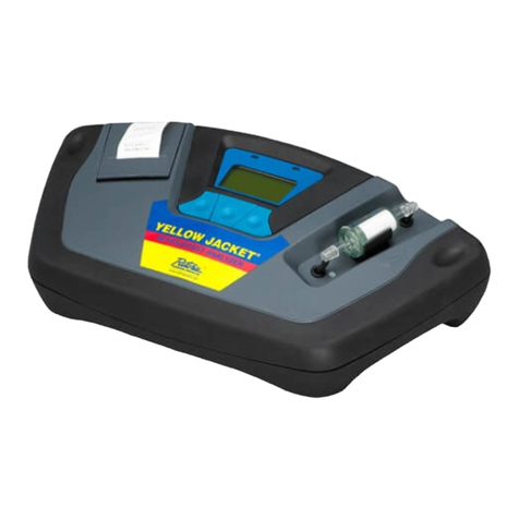
Neutronics YELLOW JACKET 68945 User manual

Neutronics
Neutronics ULTIMA ID User manual

Neutronics
Neutronics ULTIMA ID PRO RI-700H User manual
