Neutronics NTRON Mini-ICS User manual
Process Instruments
Engineered Solutions for Gas Detection and
A
nalysis
MODEL Mini-ICS
OXYGEN ANALYZER / CONTROLLER – PERCENT RANGE
OPERATIONS MANUAL
MODE
NORMAL FAULT LOW FLOW O2ALARM
20.9
PERCENTOXYGEN
MODEL Mini-ICS O2Controller
Neutronics
!
Reference Manual for
Installation and
Operation Instructions
Manual Part Number: 5-06-4900-53-0
Document Control Number: MN-A-0031
Revision Level: B – ECO 7822
Revision Date: April 14, 2006
A DIVISION OF
456 Creamery Way, Exton, PA 19341
www.neutronicsinc.com


Table of Contents
TABLE OF CONTENTS....................................................... III
FOR YOUR SAFETY:........................................................ VII
WELCOME
1CHAPTER 1 – INTRODUCTION AND OVERVIEW......................... 1-1
................................................................ VIII
1.1 GENERAL ........................................................... 1-1
1.2 FEATURES .......................................................... 1-2
1.3 SYSTEM HARDWARE OVERVIEW ............................................. 1-3
1.3.1 Main Board.................................................... 1-3
1.3.2 Relay Board................................................... 1-3
1.3.3 Power Supply.................................................. 1-3
1.3.4 Display Board................................................. 1-3
1.3.5 Control Panel................................................. 1-4
1.3.6 Chassis....................................................... 1-4
1.4 SYSTEM INPUTS AND OUTPUTS ............................................ 1-6
1.4.1 Oxygen Sensor Input........................................... 1-6
1.4.2 Flow Switch Status Input...................................... 1-6
1.4.3 O2Alarm Relay Output ......................................... 1-6
1.4.4 Inert Gas Control Relay Output................................ 1-6
1.4.5 Fault Relay Output............................................ 1-7
1.4.6 Remote Calibration Relay Output............................... 1-7
1.4.7 Analog Voltage Output......................................... 1-7
1.4.8 Analog Current Output:........................................ 1-7
1.4.9 Range ID Output............................................... 1-8
1.4.10 Service Port.................................................. 1-8
1.5 FRONT PANEL USER INTERFACE ........................................... 1-1
1.5.1 The “UP” Pushbutton........................................... 1-1
1.5.2 The “DOWN” Pushbutton......................................... 1-1
1.5.3 The “MODE” Pushbutton......................................... 1-1
1.5.4 7-Segment Alphanumeric Display................................ 1-1
1.5.5 Normal Indicator LED.......................................... 1-1
1.5.6 O2Alarm Indicator LED ........................................ 1-1
1.5.
1.5.
2CHAPTER 2 – SYSTEM INSTALLATION AND START-UP.................. 2-3
7Low Flow Indicator LED........................................ 1-1
8Fault Indicator LED........................................... 1-2
2.1 INSTALLING THE ANALYZER .............................................. 2-3
2.1.1 Step 1 – Locate and Mount the Analyzer unit................... 2-4
2.1.2 Step 2 – Install the Oxygen Sensor............................ 2-5
2.1.3 Step 3 – Install the Analyzer................................. 2-5
2.1.3.1 Oxygen Sensor Input....................................... 2-8

2.1.3.2 Flow Switch Status Input.................................. 2-8
2.1.3.3 Oxygen Alarm Relay Outputs................................ 2-8
2.1.3.4 Inert Gas Control Relay Outputs........................... 2-9
2.1.3.5 Fault Relay Outputs....................................... 2-9
2.1.3.6 Remote Calibration Relay Outputs.......................... 2-9
2.1.3.7 Analog Voltage Output.................................... 2-10
2.1.3.8 Analog Current Output.................................... 2-10
2.1.3.9 Range ID Output.......................................... 2-10
2.1.3.10 RS-232 Service Port..................................... 2-11
2.1.3.11 Battery Backup.......................................... 2-11
2.1.3.12 Mains Power............................................. 2-12
2.2 STARTING UP AND COMMISSIONING THE SYSTEM ............................... 2-13
2.2.1 STEP 1 – Power Up the unit................................... 2-13
2.2.2 STEP 2 – Calibrate the Unit.................................. 2-15
2.2.3 STEP 3 –Set Alarms, and Inert Gas Control Limits............. 2-15
2.2.3.1 Set Oxygen Alarm Level................................... 2-15
2.2
2.2
3CHAPTER 3 – ANALYZER OPERATION................................ 3-1
.3.2 Set High Inert Gas Control limit......................... 2-15
.3.3 Set Low Inert Gas Control limit.......................... 2-15
3.1 SYSTEM ORGANIZATION ................................................. 3-1
3.2 USER MODES ........................................................ 3-1
3.2.1 CALIBRATE Mode................................................ 3-1
3.2.1.1 When to calibrate......................................... 3-1
3.2.1.2 What gases to use......................................... 3-1
3.2.1.3 Procedure for calibrating the Model Mini-ICS.............. 3-2
3.2.2 SET O2ALARM Mode ............................................. 3-3
3.2.3 SET HIGH INERT GAS CONTROL LIMIT Mode......................... 3-3
3.2.4 SET LOW INERT GAS CONTROL LIMIT Mode.......................... 3-3
3.2.5 VIEW ACTIVE FAULTS Mode....................................... 3-3
3.3 RUN MODES ......................................................... 3-5
3.3.1 NORMAL Mode................................................... 3-5
3.3.2 O2ALARM ACTIVE Mode .......................................... 3-5
3.3.
3.3.
4CHAPTER 4 – MAINTENANCE AND TROUBLESHOOTING................... 4-1
3INERTING CONTROL ACTIVE Mode.................................. 3-6
4FAULT ACTIVE Mode............................................. 3-7
4.1 SYSTEM SETUP ....................................................... 4-1
4.1.1 System Setup via Front Panel Keypad........................... 4-1
4.1.1.1 User Setup 1: ICS and O2 Alarm Relays Failsafe/Non Failsafe.4-2
4.1.1.2 User Setup 2: O2 Alarm Relays Ascending Trip.............. 4-2
4.1.1.3 User Setup 3: Analog Voltage Output Setting............... 4-2
4.1.1.4 User Setup 4: Analog Current Output Setting............... 4-2
4.1.1.5 User Setup 5: Display Range Setup......................... 4-2
4.1.1.6 User Setup 6: RS-232 Baud Rate............................ 4-2

4.1.1.7 User Setup 7: Serial Output Format........................ 4-2
4.1.1.8 User Setup 8: Sensor Disconnect Detection Test............ 4-3
4.1.1.9 User Setup 9: Minimum Analog Output Voltage Concentration. 4-3
4.1.1.10 User Setup 10: Maximum Analog Output Voltage Concentration4-3
4.1.1.11 User Setup 11: Minimum Analog Output Current Concentration4-3
4.1.1.12 User Setup 12: Analog Current Full Scale................. 4-3
4.1.1.13 User Setup 13: Set Current Year. ** NOT ACTIVE FOR THIS
RELEASE** 4-4
4.1.1.14 User Setup 14: Set Current Month. ** NOT ACTIVE FOR THIS
RELEASE** 4-4
4.1.1.15 User Setup 15: Set Current Day. ** NOT ACTIVE FOR THIS RELEASE**
4-4
4.1.1.16 User Setup 16: Set Current Hour. ** NOT ACTIVE FOR THIS
RELEASE** 4-4
4.1.1.17 User Setup 17: Set Current Minute. ** NOT ACTIVE FOR THIS
RELEASE** 4-4
4.1.1.18 User Setup 18: Factory Setup Restore..................... 4-4
4.1.2 System Setup via Service Port................................. 4-4
4.1.2.1 RS-232 Service Port Interfacing with HyperTerminal in Microsoft
Windows 95 or later................................................ 4-4
4.1.2.2 Troubleshooting Your HyperTerminal Interface.............. 4-5
4.1.2.3 Organization of RS-232 Serial Data........................ 4-5
4.1.2.4 Standard Level Access..................................... 4-6
4.1.2.5 Advanced Level 1 Access................................... 4-9
4.1.2.6 Advanced Level-2 Access................................... 4-9
4.1.2.7 SETTING UP THE MODEL Mini-ICS – The RS-232 User Setup Menu4-10
4.1.2.8 System Information Display............................... 4-10
4.1.2.9 (U20) Alarm and Relay Setup Menu......................... 4-10
4.1.2.10 (U30) Analog Output Setup Menu.......................... 4-12
4.1.2.11 (U04) Display/Analog Output Range....................... 4-15
4.1.2.12 (U50) RS-232 Serial Setup Menu.......................... 4-15
4.1.2.13 (U60) Front Panel Locks Menu............................ 4-16
4.1.2.14 (U70) Auto Calibration Setup Menu....................... 4-17
4.1.2.15 Sensor Disconnect Test.................................. 4-18
4.1.2.16 Set Time-of-Day and Date ** NOT ACTIVE FOR THIS RELEASE**4-19
4.1.2.17 Averaging Window Size................................... 4-19
4.1.2.18 Auto Return to Run Mode Time............................ 4-19
4.1.2.19 Return all Settings to Factory Delivered Settings....... 4-19
4.1.3 Change factory settings via Hardware Jumpers................. 4-20
4.1.3.1 Analog Voltage Output.................................... 4-20
4.2 ROUTINE PERIODIC MAINTENANCE ......................................... 4-22
4.3 TROUBLESHOOTING .................................................... 4-23
4.3.1 Fault Codes.................................................. 4-23
4.3.1.1 Fault Code 0 – Constant Memory Error..................... 4-23
4.3.1.2 Fault Code 1 – Low Flow.................................. 4-23
4.3.1.3 Fault Code 2 – Sensor disconnected....................... 4-23
4.3.1.4 Fault Code 4 – Low Sensor Limit higher than Low ICS Limit 4-23
4.3.1.5 Fault Code 5 – High ICS Limit lower than Low ICS Limit... 4-24
4.3.1.6 Fault Code 6 – Unstable Calibration Sample............... 4-24
4.3.1.7 Fault Code 7 – Sensor Calibration signal high............ 4-24
4.3.1.8 Fault Code 8– Sensor Calibration Signal Low.............. 4-24
4.3.1.9 Fault Code 9 – Sensor Analog-to-Digital Converter Time-Out4-24
4.3.1.10 Fault Code 10 – Sensor Operating Signal Low............. 4-25
4.3.1.11 Fault Code 11 – Calibration Period too Short............ 4-25
4.3.1.12 Fault Code 17 – Bad cell Calibration Coefficient........ 4-25
4.3.1.13 Fault Code 18 – Main-board EEPROM corrupted............. 4-25
4.3.1.14 Fault Code 27 – Auto Calibration Mode active............ 4-25

4.3.1.15 Fault Code 28 – Calibration Mode active................. 4-25
4.3.1.16 Fault Code 29 – Manual Relay Control active............. 4-25
4.3.1.17 Fault Code 30 – User Setup Mode active.................. 4-26
4.3
4.3
5CHAPTER 5 – APPENDICES........................................ 5-1
.1.18 Fault Code 31 – Factory Setup Mode active............... 4-26
.1.19 Fault Code 32 – Program Starting........................ 4-26
5.1 APPENDIX A – SPARE PARTS LIST ........................................ 5-1
5.2 APPENDIX B - SPECIFICATIONS .......................................... 5-2
5.3 APPENDIX C – ANALYZER FACTORY CONFIGURATION SETTINGS5-5
5.4 APPENDIX D – FRONT PANEL HOT-KEY FUNCTIONS............................ 5-7
5.5 APPENDIX E – WARRANTY ............................................. 5-8
INTENDED USE FOR THE MODEL MINI-ICS....................... 5-8
5.6 APPENDIX F – REFERENCE DRAWINGS ..................................... 5-9
5.7 APPENDIX G – MOUNTING CONFIGURATIONS ................................ 5-10
5.7.1 Wall Mount Enclosure......................................... 5-10
5.7.2 Rack Mount Enclosure......................................... 5-11
5.7.3 Explosion Proof Enclosure.................................... 5-12

For Your Safety:
PLEASE READ THIS MANUAL IN ITS ENTIRETY BEFORE ATTEMPTING
INSTALLATION OR OPERATION! Attempting to operate the
Model 1100 without fully understanding its features and
functions may result in unsafe conditions
• Always use protective eye wear and observe proper safety procedures
when working with pressurized gases.
• Properly dispose of the Oxygen sensor according to the MSDS and local
policies when it has expired.
• Ensure the MODEL Mini-ICS has been properly calibrated before use.
• Never expose the analyzer chassis or sensor to water, high humidity or
moisture. The analyzer chassis is not watertight.
• Never expose the MODEL Mini-ICS to flame or high temperatures. Never
expose the Model Mini-ICS analyzer to flammable gases or vapors. The
Mini-ICS is not rated Intrinsically Safe.
• Ensure the analyzer unit is mounted in an area with free airflow to
prevent the chassis from exceeding the operating temperature
specifications. Do not mount the analyzer or sensor against hot
surfaces. Do not block the ventilation louver on the analyzer
chassis.

WELCOME
Thank you for purchasing the Model Mini-ICS
Analyzer for percent range Oxygen measurement.
The Model Mini-ICS Compact Analyzer is a user friendly, microprocessor
controlled Oxygen measuring instrument. It has many features to offer the
user, which will be described in this manual. We recommend that all
personnel who use this instrument read this manual to become more familiar
with its proper operation.
For further detail regarding the maintenance and in-field service of the
Model Mini-ICS analyzer, please contact the Neutronics Inc. Application
Engineering Department. If you have questions or comments, we would like
to hear from you.
Neutronics Inc. Customer Service Department
456 Creamery Way
Exton, PA 19341
Tel: 610) 524-8800 ext 136
Toll Free: (800) 378-2287 ext 136 (US only)
Fax: (610) 524-8807
EMAIL: [email protected]
Visit us at www.neutronicsinc.com
Equipment Serial Number:
(For faster service, please have this number ready if for any reason you need to contact
us about your instrument)
Copyright ©2003 Neutronics Inc.
This work is protected under Title 17 of the US Code and is the sole property of
Neutronics Inc. No part of this document may be copied or otherwise reproduced, or
stored in any electronic information retrieval system, except as specifically permitted
under US copyright law, without the prior written consent of Neutronics Inc.
1 CHAPTER 1 – INTRODUCTION AND OVERVIEW
sensor
1.1 General
The Model Mini-ICS [Inert Gas Control System] analyzer by Neutronics
offers a cost effective solution in a small package for industrial
process Oxygen measurement and inert gas control applications for flash-
fire/explosion prevention, or product quality. The Model Mini-ICS is a
custom analytical instrument, designed to accurately measure 0.1 to
50.0% Oxygen, and provide direct control of Oxygen levels in your
process by controlling inert gas purging.
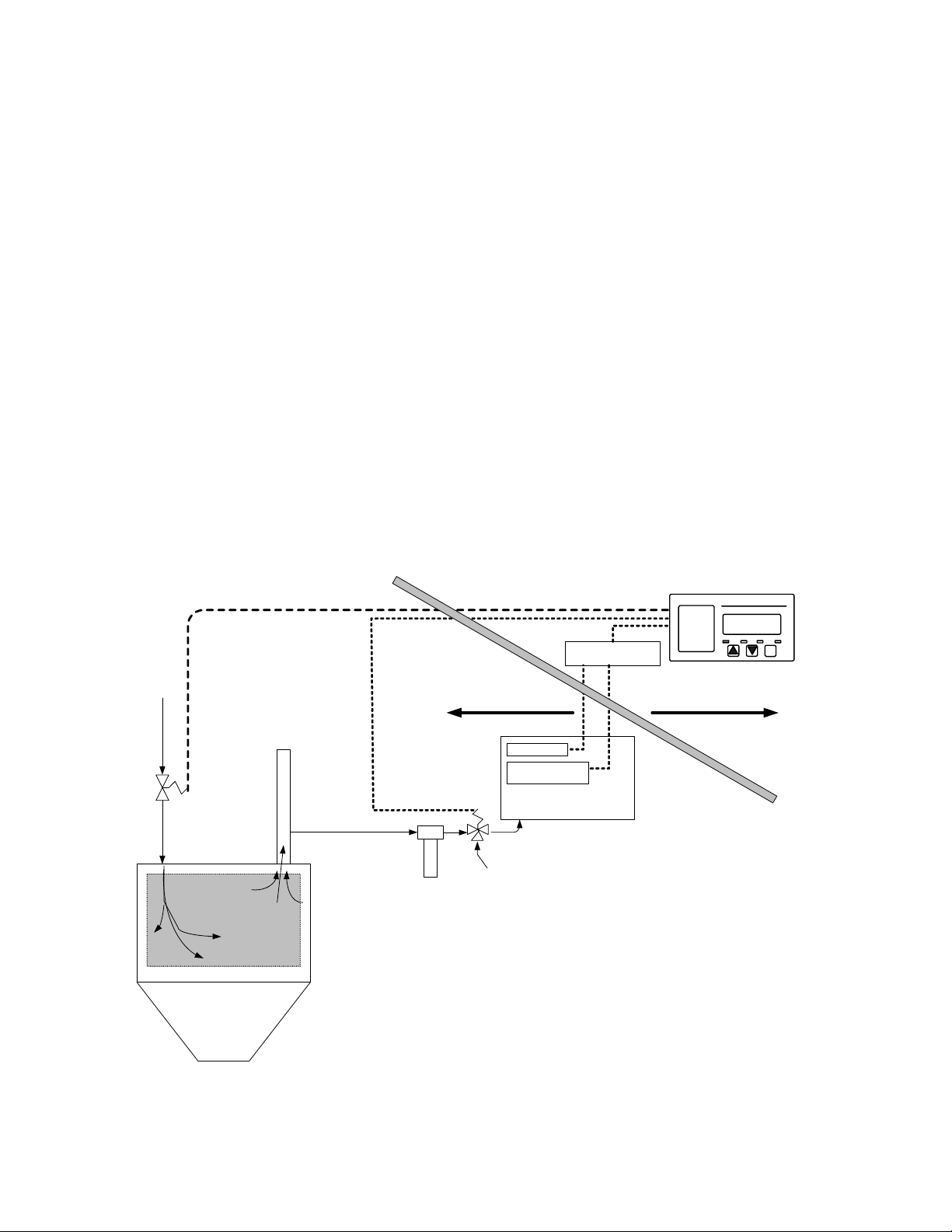
At the heart of the analyzer is a remote-mounted Neutronics zero-
maintenance, disposable galvanic Oxygen sensor. Remote mounting allows
the sensor to be installed close to a process sampling point for the
fastest response time possible. Neutronics also offers a variety of
process sampling and sample conditioning solutions for
reliability and longevity.
Pre-Filter
Sample Conditioning
Package
O2 Sensor
Loss of Sample
Sensor
Inert Gas Input
(Nitrogen)
Vent
Analyzer (Control Module)
Safety Barriers
SAFE AREAHAZARDOUS AREA
Inert Gas
Control Valve
Remote
Cal
Solenoid
Valve
1100-ICS
Gas Head-Space
Industrial Mixer,
Centrifuge, Reactor,
Blender, etc.
Figure 1
–
Complete process Oxygen
m
onitor and control system example
Manual Part Number:
5-06-4900-53-0 Revision Level: B
ECO 7822 Revision Date:
April 14, 2006 Page
1-1

System Installation and Startup
1.2 Features
The Model Mini-ICS analyzer module is designed to be flush mounted to a
panel or console. Packaging options available from Neutronics Inc.
include General Purpose and Explosion Proof surface-mount enclosures,
and custom rack-mount designs. Because of the small size of the Model
Mini-ICS analyzer, the basic panel-mount unit can be integrated into a
variety of equipment or control panels.
Figure 2 – analyzer
MODE
NORMAL FAULT Low Flow O2 Alarm
20.9
PERCENTOXYGEN
MODEL Mini-ICS O2Analyzer
Neutronics
Color Coded LED’s:
NORMAL = Green
FAULT = Yellow
Low Flow = Red
O2 Alarm = Red Large Buttons
for Ramp Up and
Ramp Down for
Display and
Mode Control
Large Mode Select
Button for easy
scrolling through
menu options
Large LED
Digital Display
Reference Manual for
Installation and
Operation Instructions
!
Other Features Include:
• User-adjustable Oxygen Alarm with relay output for process control use
• User-adjustable Inert Gas Control function with relay output for
process control use. Inert Gas Control features user-adjustable high
and low set point hysteresis
• Loss of Flow indication for extractive process sampling applications
• Double Redundant system configuration backup file, with automatic
repair function
• Convenient Remote calibration relay output for “one-man” calibration
in applications where the Oxygen sensor is a long distance from the
Mini-ICS Analyzer
• Two Analog Outputs: 4-20 mA AND 0-1, 0-5, or 0-10 VDC
• Auto Ranging or Fixed Range Oxygen Measurement (VDC output provided
for auto-range identification)
• Bi-directional RS-232 Serial Interface for connection to a PC,
terminal, or printer
System Hardware Overview
1.3 System Hardware Overview
Chassis
Power Supply Board
Relay Board
Main Board
Display
Board
Control
Panel
Figure 3 – basic analyzer
1.3.1Main Board
The main board houses the microprocessor, and supporting electronics for
controlling the operation of the Model Mini-ICS Analyzer. The main
board receives the sensor signal and flow switch inputs, and provides
the control and display functions of the analyzer.
1.3.2Relay Board
The Relay Board houses relay contacts for all of the Alarm and Control
features of the Mini-ICS. The relays are mapped discretely to each
alarm or control function to provide electrical outputs for reporting,
and process control use.
1.3.3Power Supply
The power supply board is designed to take 110/220 VAC, 50/60 Hz (90-264
VAC, 47-63Hz). as input. The supply is internally fused directly on the
board. An optional 24VDC (10-30 VDC) power supply is available for
installations where a DC voltage is required to power the Model Mini-
ICS. A 12VDC battery-backup power input (battery not provided) is also
provided to act as a back up in case of main power failure.
1.3.4Display Board
The Display board is designed to generate a digital indication of the
concentration of Oxygen, and error codes. The display is a 7-segment,
¾” Alphanumeric LED for easy viewing from a distance.

System Installation and Startup
1.3.5Control Panel
The Control Panel serves as the main user interface. The Control Panel
features the keypad (ramp-UP, ramp-DOWN, and MODE keys) and the status
LED’s. The control panel is designed to be splash and water-resistant.
At the four corners of the panel are the #8-32 mounting studs, which
allow flush mounting of the instrument to a control or equipment panel.
The gasketed panel is suitable for NEMA type 4 / IP20 environments when
properly installed.
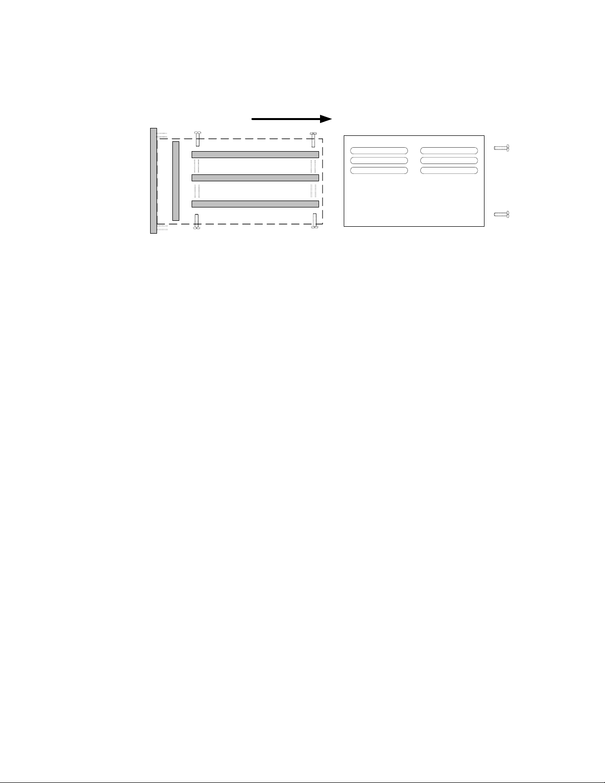
1.3.6Chassis
The chassis is manufactured of specially coated steel. It is designed
to provide a general level of protection against mechanical damage from
the local environment. It is also an important component of the ESD
shielding design. Since the Model Mini-ICS is a flush mounted system,
the portion of the instrument housed in the chassis will be located
behind the control panel or embedded within the customer equipment
enclosure. The enclosure is general purpose and is not watertight.
Analyzer
Electronics
Package is
inserted here
Figure 4 – analyzer
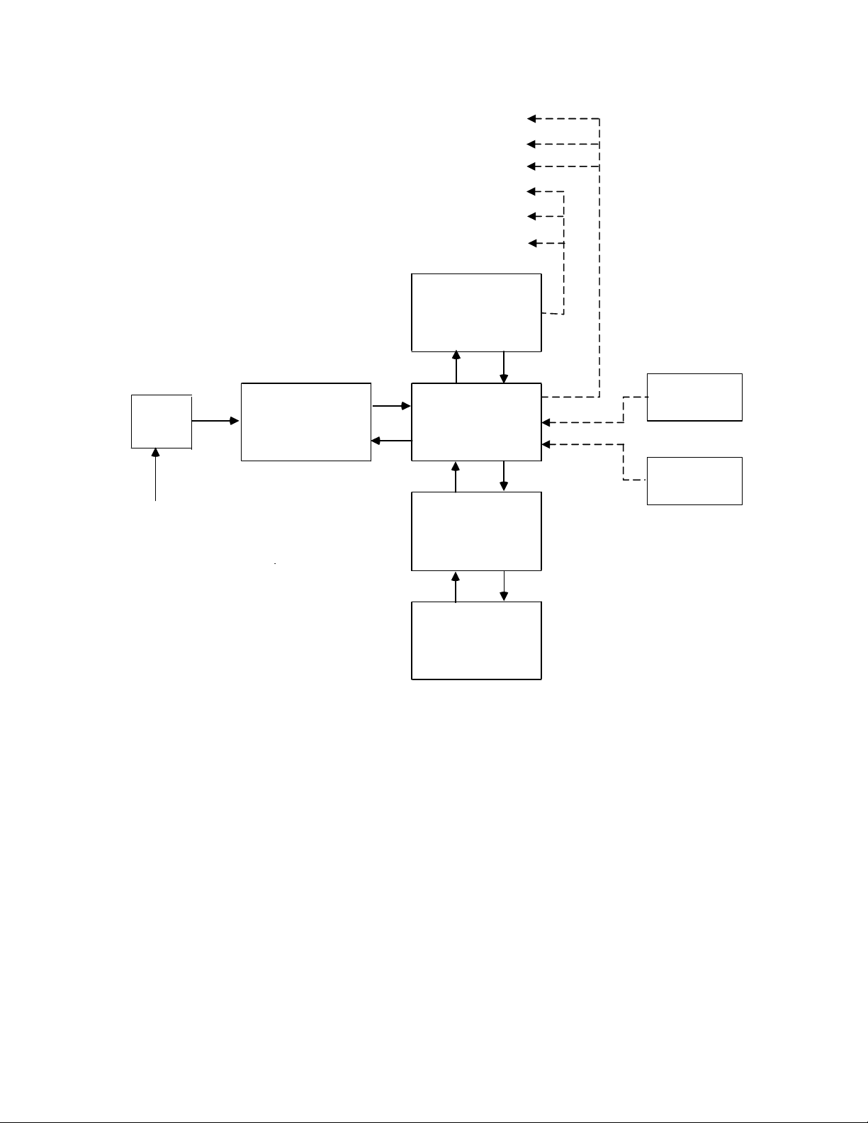
System Hardware Overview
Relay Board
RS 232 COM Line
Mains Power
Input
Power
Supply Main Board
Display
Board
Contr ol
Panel
Line
Filter
Fault andRemoteCalibration Relay Outputs
O2Alarm & Inert Gas Control Relay Outputs
Range IDOutput
Analog Voltage Output
Sensor
4-20 mA Output
Flow
Switch
Figure 5 – analyzer system configuration

System Installation and Startup
1.4 System Inputs and Outputs
1.4.1Oxygen Sensor Input
The Oxygen Sensor electrical input is used to indicate the Oxygen level
concentration in a process vessel headspace, or a process gas stream.
Sensors are available to measure the Oxygen concentration in percent by
volume or partial pressure in the ranges from 0.1% to 25.0%, and 0.1% to
50.0%. All available Neutronics Inc. Sensors are Intrinsically Safe,
remote-mounted devices, and may be interfaced through electrical safety
barriers for hazardous applications,
1.4.2Flow Switch Status Input
The Flow Switch Status electrical interface is used to indicate the flow
status of sample gas from the process to the Oxygen Sensor, for
extractive applications where a Neutronics Inc. Sampling System has been
provided. A closed flow switch indicates sufficient sample flow. An
open Flow Switch indicates that sample flow has dropped below the
mechanical set point of the Flow Switch. In this flow condition, the
Oxygen reading may not be representative of the process Oxygen level.
Neutronics Inc. Flow Switches are Intrinsically Safe, and may be
interfaced through electrical safety barriers for hazardous
applications.
1.4.3O2Alarm Relay Output
The Oxygen Alarm relay is mapped to the O2Alarm setpoint, and is
provided for process control use. The user may set the level at which
the O2Alarm activates (section 3.2.2). The O2Alarm may be configured
as ascending (highest Oxygen level allowable) or descending (lowest
Oxygen level allowable) activation. The relay output may be configured
for fail-safe (relay coil de-energized in alarm state) or non fail-safe
(relay coil energized in alarm state) activation. Factory default
settings are ascending, and fail-safe (Appendix C, Factory
Configuration). The O2Alarm relay contacts are form C (DPDT), voltage-
free.
1.4.4Inert Gas Control Relay Output
The Inert Gas Control (ICS) relay is mapped to the Inert Gas Control
high and low limit setpoints, and is provided for process control use.
The user may set the levels at which Inert Gas Control activates (high
limit setpoint), and de-activates (low limit setpoint). The relay
output may be configured for fail-safe (relay coil de-energized in alarm
state) or non fail-safe (relay coil energized in alarm state)
activation. The factory default setting is fail-safe (Appendix C,
Factory Configuration). The ICS relay contacts are form C (DPDT),
voltage-free.

System Hardware Overview
The purpose of the ICS relay is to control the flow of inert gas to the
process being monitored, to keep Oxygen levels in the process within an
acceptable range at all times. Purging the process with inert gas
lowers the Oxygen concentration in the process. The Mini-ICS Analyzer
will activate the ICS relay when the Oxygen concentration rises to the
High ICS limit setpoint. It will deactivate the ICS relay when the
Oxygen concentration falls below the Low ICS limit (sections 3.2.3 and
3.2.4).
1.4.5Fault Relay Output
The Fault relay output is used to indicate that there is at least one
system fault active on the Model Mini-ICS Analyzer (section 4.3.1 –
fault codes and definitions). The Fault relay contacts are Form B
(SPST), voltage-free.
Note: The user can configure the ICS relay to activate on certain Fault
conditions for process safety applications (sections 4.1.2.9, and
Appendix C).
1.4.6Remote Calibration Relay Output
The Remote Calibration relay is used to activate a valve that flows
calibration gas to the sensor during gas calibration. This is a
convenience item for applications where the sensor/sampling system is a
long distance from the analyzer. The Calibration relay is mapped to the
analyzer Calibration function. It activates whenever the user initiates
a gas calibration routine by entering CAL mode (section 3.2.1), closing
off the flow of process gas and introducing calibration gas to the
Oxygen Sensor. The Remote Calibration relay contacts are Form B (SPST),
voltage-free.
1.4.7Analog Voltage Output
The Analog Voltage output is used to indicate to a remote device (user
control system, chart-recorder, etc.), the displayed Oxygen
concentration in dynamic electrical potential. The Analog voltage can
vary from 0 volts for minimum-scale-deflection, to either 1, 5 or 10
volts full-scale. The Analog voltage output is scaled according to the
analyzer’s active range, and must be used in conjunction with the Range
ID voltage when the Analyzer is configured for auto-ranging (section
1.4.9).
1.4.8Analog Current Output:
The Analog Current output is used to indicate to a remote device (user
control system, chart-recorder, etc.), the displayed Oxygen
concentration in dynamic electrical current flow. The minimum scale
deflection may be set to either 0 mA or 4 mA. Full-scale is fixed at 20
mA. The Analog current output is scaled according to the analyzer’s
active range, and must be used in conjunction with the Range ID voltage
when the Analyzer is configured for auto-ranging (section 1.4.9).

System Installation and Startup
1.4.9Range ID Output
To remotely detect the present range of Oxygen concentration, the Model
Mini-ICS features a 0-10 volt Auto-Range Identification output. The
Range ID output is used in conjunction with the Analog Voltage and
Analog Current outputs when auto-ranging is used. It provides an
indication of the Analog outputs’ current full-scale. There are four
voltage levels are used in the Mini-ICS:
• For a Full Scale of 1%, the Range ID output is 5.63 Volts
• For a Full Scale of 10%, the Range ID output is 6.25 Volts
• For a Full Scale of 25%, the Range ID output is 6.88 Volts
• For a Full Scale of 50%, the Range ID output is 7.50 Volts
• For a Manual Scale, the Range ID output is 9.30 Volts
1.4.10 Service Port
The Service port provides a user-friendly means of digital
communications with the Model Mini-ICS Analyzer. Through this port, the
unit may be configured, calibrated, and queried for most functions. The
RS-232 port may also be programmed to send out information on a timed
basis for users who prefer to use digital instead of Analog interfacing
with the analyzer. In addition, the service port may be used with a PC
based computer (such as a portable notebook computer) over a standard
bi-directional RS-232 serial interface.

1.5 Front Panel User Interface
1.5.1The “UP” Pushbutton
The “UP” pushbutton can be used to program the Mini-ICS Analyzer via the
front panel. This momentary push-button soft key is used to enter
incremental information. Its function is menu-driven.
1.5.2The “DOWN” Pushbutton
The “DOWN” pushbutton can be used to program the Mini-ICS Analyzer via
the front panel. This momentary push-button soft key is used to enter
decremental information. Its function is menu-driven.
1.5.3The “MODE” Pushbutton
The “MODE” pushbutton can be used to program the Mini-ICS Analyzer via
the front panel. This momentary push-button soft key is used to
navigate the operational modes available through the front panel. Its
function is menu-driven.
1.5.47-Segment Alphanumeric Display
The 7-Segment alphanumeric display feeds back information from the Mini-
ICS to the user via the front panel. The primary purpose of the 7-
Segment display is to show the Oxygen concentration readout. It is also
used for feedback information during modes of operation, Fault codes,
and operational mode indications, such as setup and calibration.
1.5.5Normal Indicator LED
The purpose of the NORMAL Indicator LED is to inform the user via the
front panel that the Model Mini-ICS is measuring the concentration of
the sample gas and updating the display and outputs accordingly, and has
not detected any Alarm, or Fault conditions.
1.5.6O2Alarm Indicator LED
The purpose of the O2Alarm Indicator LED is to inform the user via the
front panel that the O2Alarm and its associated relay are in active
mode.
1.5.7Low Flow Indicator LED
The purpose of the Low Flow Indicator LED is to inform the user via the
front panel that the sample gas flow from the process to the Oxygen
sensor is below the mechanical set point of the flow switch. Since Low
Flow is considered a system Fault condition, when the Low Flow LED is
active, the Fault relay will also be active
Manual Part Number:
5-06-4900-53-0 Revision Level: B
ECO 7822 Revision Date:
April 14, 2006 Page
1-1

System Installation and Startup
1.5.8Fault Indicator LED
The purpose if the Fault Indicator LED is to inform the user via the
front panel that at least one system fault, other than the Low Flow
Fault is active. Note that when the Fault Indicator LED is active, the
Fault relay will also be active.

Installing the Analyzer
2 CHAPTER 2 – SYSTEM INSTALLATION AND START-UP
2.1 Installing the Analyzer
STEP 1:
LOCATE THE ANALYZER...
PANEL CUTOUT
STEP 2:
INSTALL THE SENSOR…
Sampling Package
STEP 3:
INSTALL TH ALYZERE AN
Figure 6 – installation outline
Manual Part Number:
5-06-4900-53-0 Revision Level: B
ECO 7822 Revision Date:
April 14, 2006 Page
2-3

System Installation and Startup
2.1.1Step 1 – Locate and Mount the Analyzer unit
The Model Mini-ICS is designed to be mounted flush to the surface of
equipment or on a control panel. Select a suitable location for the
Model Mini-ICS analyzer unit where the digital display and status LED’s
will be easy to read, and the interface buttons on the display panel
will be easy to access.
The analyzer should not be exposed to water, adverse temperature, or
shock. Ensure the analyzer unit is mounted in an area of free airflow to
prevent the chassis from exceeding the operating temperature
specifications. Do not mount the analyzer or sensor against hot
surfaces. Do not block the ventilation louver on the analyzer chassis.
To maintain a watertight seal on the control panel, ensure that all
burrs and deformities at the cutout and mounting holes are removed
before insertion of the analyzer unit into the cutout. Ensure that a
proper seal is made at the gasket on the model Mini-ICS control panel.
Installation of the analyzer chassis requires four clearance holes for
the #8-32 threaded studs and a cutout in the control panel to allow the
chassis to slide flush to the panel. Make sure there are no burrs or
sharp edges in the cutout or mounting-holes, which would interfere with
the gasket on the analyzer control panel. The gasket ensures a
watertight seal around the control panel. The control panel, when
properly installed is suitable for NEMA Type 4, IP66 environments. The
rear electronics enclosure is suitable for NEMA Type 1, IP 20
environments.
2.91"
6.20"
6.62"
2.75"
PANEL CUTOUT & DRILL PATTERN
.169 DIA. HOLE
4 PLACES
Figure 7 – analyzer
Table of contents
Other Neutronics Measuring Instrument manuals

Neutronics
Neutronics YELLOW JACKET 68945 User manual

Neutronics
Neutronics ULTIMA ID PRO RI-700H User manual

Neutronics
Neutronics 7100E User manual

Neutronics
Neutronics QUICK DETECT User manual

Neutronics
Neutronics MINI ID User manual

Neutronics
Neutronics ULTIMA ID User manual

Neutronics
Neutronics UltimaID User manual


