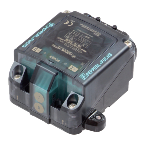
New Cosmos Electric KD-12O User manual

Diffusion Oxygen Detector
Model KD-12O
Instruction Manual
zKeep this instruction manual where it is readily accessible.
zThoroughly read this instruction manual before using the equipment so it can be used
safely and correctly.
zThis manual provides information concerning standard specifications. If the specifications
of your model are nonstandard, refer to the delivery specifications.
Instruction Manual No.
GAE-036-00
May 2010
New Cosmos Electric Co., Ltd.

•Nomenclature
See pages 4 to 6.
•Replacement of Sensor Unit
See pages 20 and 21.
•Wiring and Connecting
Methods
See pages 11 to 14.
Ground terminals
24 V
power
supply
Indicator
E.g., External
alarm
Shield
•Display and Operation in
Each Mode
See page 17.
•Maintenance Check and
Operation Methods
See pages 18 to 25.
•Troubleshooting
See page 26.

Table of Contents
1. Introduction.......................................................................................................................1
2. Precautions.......................................................................................................................2
3. Contents of Package ........................................................................................................3
4. External Dimensions and Nomenclature...........................................................................4
4-1. Main Unit................................................................................................................4
4-2. Display and Control Blocks.....................................................................................5
4-3. Terminal Block........................................................................................................6
5. Installation.........................................................................................................................7
5-1.Installation Method ..................................................................................................7
5-2. Mounting of Optional Items......................................................................................9
6. Wiring Method.................................................................................................................10
6-1. Wiring Work..........................................................................................................10
6-2. Wiring and Connection.........................................................................................11
7. Precautions before Use ..................................................................................................14
7-1.Oxygen Deficiency.................................................................................................14
8. Display at Start-up (Initial Delay).....................................................................................15
9. Display and Operation in Each Mode .............................................................................16
10. Trouble Alarm ..............................................................................................................17
11. Maintenance Check and Operation Method..................................................................18
11-1. Daily Inspection and Periodical Inspection...........................................................18
11-2. Replacement of Sensor Unit.................................................................................19
11-3. Calibration Method ...............................................................................................21
Maintenance Mode..............................................................................................................21
Span Rough Adjustment ......................................................................................................22
21.0 vol% Adjustment..........................................................................................................23
Full-scale and Alarm Set Value Display...............................................................................24
Test Mode ............................................................................................................................25
12. Troubleshooting...........................................................................................................26
13. Specifications...............................................................................................................27
14. Warranty......................................................................................................................28
15. Detection Principle.......................................................................................................29
16. Glossary........................................................................................................................30

1
1. Introduction
•Thank you for purchasing the KD-12O Diffusion Oxygen Detector.
•In order to ensure the correct and safe operation of this product, be sure to read this
manual before use.
•The KD-12O Diffusion Oxygen Detector detects oxygen leaks and oxygen deficiency in
working environments of semiconductor manufacturing plants. It displays the oxygen
concentration and also outputs an analog signal (4 to 20 mA DC) indicating the oxygen
concentration to an external device. If a preset oxygen concentration is reached, the red
alarm lamp and alarm relays will operate, making this Detector useful in monitoring
oxygen concentrations.
•Maintenance and inspection are indispensable to the reliable performance of the Gas
Detection/Alarm System. Be sure to perform the maintenance checks described in this
manual.
Explanation of Symbols
The following symbols are used to indicate and classify precautions in this manual.
DANGER Indicates information that, if not heeded, is likely to result in death or
serious injury.
WARNING Indicates information that, if not heeded, could possibly result in death or
serious injury.
CAUTION Indicates information that, if not heeded, could result in minor injury, or
damage to the product.
MEMO Indicates advice on handling the product.

2
2. Precautions
•Read this manual completely and be sure you understand the information provided herein
before attempting to use the product.
•Abide by all applicable laws and regulations when using this product.
WARNING
zBe sure to ground the product to prevent electric shocks.
zIf there is a gas leak alarm, take the necessary measures in accordance with your
company's regulations.
CAUTION
zLicensed members should implement all necessary work for the product including wiring
and installation in accordance with all applicable laws and regulations.
zDo not disassemble the product or modify the construction or electric circuits of the
product. Otherwise, the explosion-proof construction of the product may be adversely
affected.
zDue to the presence of high concentrations of SO2 and Cl2 gases, the sensor life
may be reduced and the error margin may increase.
zMeasurements performed when the atmospheric pressure of the measurement
environment is different from standard atmospheric pressure (example, at a high
altitude) do not show the correct value because of pressure dependence.
zBe sure to provide a protective cover (optional) if the product is installed outdoors.
zUse the product in accordance with applicable laws and regulations.

3
3. Contents of Package
•The product is provided with the following items. Make sure that none of these items is
missing.
•Although the product is packed and shipped with the utmost care, contact your New
Cosmos representative if there should be any damage or missing items.
Accessories Optional items
Detector head
Accessory set (see note 1)
12- and 13-mm-dia. pressure-proof packing:
1 each
Two 11-mm-dia. washers
One C-clamp
Two M5 screws
Hexagon wrench (nominal dia. 2 and 4):
1 each (see note 2)
Instruction Manual (see note 2)
MJ-1 Magnetic Stick (see note 2)
Protective cover (see note 3)
Horizontal type: KW-41
Vertical type: KW-42
PB-1 2B Pole Mounting Bracket (see note 3)
GCP-09 Calibration Cap(see note 3)
Z-001K Gas Calibration Kit(see note 3)
2 bulb hand pump
Capillary for 2 bulb hand pump
Note: 1. The standard product incorporates a built-in pressure-proof packing (12.5-mm dia.),
washer (12-mm dia.), and B-clamp.
2. Ahexagon wrench, Instruction Manual, and MJ-1 Magnetic Stick are provided for each
order.
3. The optional items are for use only by the KD-12.
WARNING
zDo not use the magnetic stick for any purposes other than the operation of this product.
zKeep in mind that when the magnetic stick attracts magnetic objects, tools, iron pieces,
etc., your hands may become pinched and injured.
zDo not touch the magnet if you are allergic to metal, otherwise your skin may become
chapped or reddened.
zGenerally speaking, magnets break easily and the corrosion of the magnet progresses
from the fracture location. Fragments of the magnet may also get in your eyes or injure
your skin.
zThe components of the magnetic stick may melt into water. Do not drink water exposed to
the magnetic stick.
zKeep the magnetic stick away from electronic medical devices, such as cardiac
pacemakers, or the magnetic stick may obstruct the normal operation of the device.
CAUTION
zKeep the magnetic stick away from magnetic tapes, floppy disks, and prepaid cards.
Otherwise, they may become magnetized and the information that they hold may be lost.
zKeep the magnetic stick away from high-precision devices, such as personal computers
and watches. Otherwise, they may malfunction.

4
4. External Dimensions and Nomenclature
4-1. Main Unit
Number Name Description
1 Casing cover
2 Casing
3 Sensor unit Incorporates a gas sensor.
4Ground terminal Used when grounding the frame.
5 State display
indicator Indicates the power supply state (green), alarm state (red), and trouble
state (yellow).
6 Control block Insert the magnetic stick to control or set the product.
7 Display block Displays the gas concentration and set values.
8
Cable gland
Used to secure the cable.
9 Bolt with hexagon
socket Used for securing the cable gland. Use a hexagon wrench with a
nominal diameter of 2 mm.
10 Bolt with hexagon
socket Used for securing the casing cover. Use a hexagon wrench with a
nominal diameter of 4 mm.
Two, 5.5 dia.

5
4-2. Display and Control Blocks
Magnetic switches
(Insert the magnetic stick to operate the magnetic switches.)
Number Name Description
1 MODE switch Makes adjustments and settings or cancels the operation of
the product.
2 ENTER switch Enters settings or completes the control of the product.
3 UP switch Makes adjustments and settings or increases set values and
other values.
4 DOWN switch Decreases set values and other values.
Number Name Description
5 Display block Displays the concentration of gas and set values.
State display indicator
Number Name Description
6 POWER indicator A green lamp to display the power supply state.
7 ALARM indicator A red lamp to display the alarm state.
8 TROUBLE indicator A yellow lamp to display the trouble state.

6
4-3. Terminal Block
Signal
ZA
ZC
24V(+)
GND
1
2
3
5
4
4〜20mA
POWER
+
−
E
2
1
3
4
5
Number Name Description
1 24 V (+) Power supply voltage (positive)
2 GND Power supply voltage (negative) and analog
signal (negative) common
3 Signal 4- to 20-mA analog signal (positive)
4 ZA
5 ZC External contact
E
Ground terminal Used to ground the frame.
Terminal block
Ground
terminal
Lever
Sensor
connector
O-ring
Clamp
4 to 20 mA
24 V (+)

7
5. Installation
5-1.Installation Method
CAUTION
zBe careful not to damage the gas detector when installing it. Otherwise, the
explosion-proof performance of the gas detector will be lost.
zWhen using the Detector to prevent oxygen deficiency (anoxia) in the
surrounding air, mount the Detector at the same height as the head of the
operator.
zInstall the gas detector in places where it can be maintained and inspected with
ease.
zDo not install the product in the following places.
- Places where the ambient temperature exceeds the operating temperature
range (0°C to 40°C).
- Places where condensation occurs.
- Places where water is directly sprayed.
- Places subject to corrosive gas.
- Places close to equipment that generates high frequencies or a magnetic field.
zInstall the gas detector in places free from vibration.
zInstall the gas detector in places free from sudden temperature changes.
zKeep the gas detector free from impacts.
zWhen installing the gas detector outdoors, be sure to install the protective cover
(optional).
zMount the gas detector at a height where maintenance inspection can be
performed easily and considering the fact that oxygen deficiency (anoxia)
occurs easily at a height of 75 to 150 cm from the floor.

8
•Mount the main unit to the wall with the M5 screws that are provided with the product. Be
sure to install the protective cover (optional) when mounting the main unit outdoors.
Mount the main unit with a 2B pole mounting bracket (optional) when mounting the main
unit to a 2B pole. Refer to 5-3 Mounting of Options for details of optional products.
・The casing cover of the Detector must be opened to connect the wiring or replace the
sensor unit. When installing the gas detector, provide sufficient space to enable the casing
cover to be opened to at least 90°.
At least 90°
センサ基板
上
から
見
たとき
Mounting hole
Mounting hole

9
5-2. Mounting of Optional Items
•Protective Cover
Horizontal Type (KW-41) Vertical Type (KW-42)
•2B Pole Mounting Bracket
CAUTION
zSecure the casing cover with M3 screws if strong winds are expected.
M3 screw

10
6. Wiring Method
6-1. Wiring Work
•Be sure to provide explosion-proof wiring if the product is to be used in hazardous places.
Cable Work
•Use a shielded cable, such as CVV-S with a thickness of 1.25 to 2.00 mm2. Lay all cables
in protective tubes, such as metal conduits or carbon steel pipes, or other protective
structure, such as a concrete duct.
•When using the external contact function of the product, which requires a five-conductor
cable, make sure that the maximum diameter of the cable conductor is 1.25 mm2. When
using only the analog signal function, which requires a three-conductor cable, without the
external contact function, make sure that the maximum diameter of the cable conductor is
2.00 mm2.
•When using the explosion-proof packing lead-in method, refer to the following table and
use a cable with the finished diameter matching the inner diameter of the packing. In order
to prevent the spread of explosive gas or fire, securely tighten the cable gland.
•It is recommended not to connect two cables together. If it is unavoidable, however,
connect them or branch them within the explosion-proof casing of the main unit.
Packing Washer
Cable outer
dia.Inner dia.Inner dia.Clamp Accessory or
Optional item
10-10.4 11.5 11
10.5 12 11 Optional item
11 12 12
C Clamp
Accessory
11.5 12.5 12 Built-in
accessory
12 13 14 B Clamp Accessory
12.5 13.5 14 Accessory
13 14 14 A Clamp Optional item
* A pressure-tight packing with a diameter of 12.5 mm, a washer with a diameter of
12 mm, and a B clamp, all of which correspond to a cable with a diameter of 11.5
mm, are built into the standard model.
* Three pressure-resistant packings with diameters of 12 mm, 13 mm, and 13.5 mm,
two washers with a diameter of 11 mm, two washers with a diameter of 14 mm, one
Aclamp, and one C clamp are provided with the standard model. These correspond
to cables with diameters of 11 and 12 mm.
* If the cable diameter is other than 10.5 or 12.5 mm, select the corresponding
pressure-resistant packing, washer, and clamp from the above table, and order
them from New Cosmos.
CAUTION
zLicensed members should implement all necessary work for the product including wiring
and installation in accordance with all applicable laws, regulations and standard.

11
CAUTION
zWire the connecting terminals correctly.
zSeparate connection cables from power lines as far as possible.
zWhen closing the casing cover, make sure that the power supply cords, harness, and
O-ring are not caught in the casing cover.
6-2. Wiring and Connection
Connecting Power Supply and Signal Wires
•Provide dedicated breakers, if needed, to lines that are connected to peripheral devices,
such as indicator units and signal converters.
•Use a dedicated cable, such as CVV-S (with a thickness of 1.25 to 2.00 mm2).
•Make sure that the power supplied to the product is within the specified voltage range.
•Make sure that the load resistance of the signal line, including the resistance of the wire, is
300 ohm or less.
WARNING
zBefore opening the casing cover of the gas detector, be sure to turn off the product and
all devices (e.g., indicator unit and signal converter) connected to the product.
zIf the power is turned ON, the power supply may become a source of ignition.
zBe sure to ground the product to prevent electric shocks.

12
MEMO
•If the main unit is grounded on the power supply side, do not connect a shielded cable
to the ground terminal (E) in the gas detector, or otherwise two-point grounding will result.
Connection Example with Power Supply Side Grounded
System Configuration Example
•For details, refer to the Instruction Manual of each device.
V2M
KD-12O
Indicator unit
Detector
GAS
VISION
S-500
Security
management system
Comprehensive gas
detection/alarm system
KD-12O
KD-12O
KD-12O
KD-12O
Detector
Single detector connected
to indicator unit Multiple detectors monitored
together
電源
2
G
roun
d
terminals
CVVS cable 24V
power
supply
Indicato
r
Shi
e
ld
External alarm
Ground terminal on
power supply side
NotgroundedGrounded
KD-12O

13
Typical Connection Procedure
(1) Prepare a power supply that can provide 24 V.
(Do not turn on the power supply before wiring the main unit.)
(2) Loosen the hexagon socket bolts on the four corners of the main unit using the provided
hexagon wrench with a nominal diameter of 4 mm, and open the casing cover of the
main unit. (See the photograph below on the left.)
(3) Remove the screws of the cable gland and insert the cable for wiring. (See the
photograph on the right.)
(4) Tighten the screws on the cable gland and secure the cable.
(5) Press the lever of the terminal block with a flat-blade screwdriver. (See the photograph
below.)
(6) The clamp will open. Insert the lead wire.
(7) Connect the positive side of the power supply to the 24 V (+) terminal.
(8) Connect the negative side of the power supply to the GND terminal.
(9) The lead wire will be automatically secured when the screwdriver is lifted.
(10)Check that the power supply cords are securely connected to the terminals. This
completes the power supply preparations.
(11)Wire the analog signal and external contact terminals, if required.
(12)Tighten the hexagon socket bolts on the four corners of the main unit and close the
casing cover of the main unit.
CAUTION
zWhen operating the lever on the terminal block, be sure that the flat-blade screwdriver
does not slip off the lever. When operating the lever on the terminal block, be sure that
the flat-blade screwdriver does not slip off the lever.
zWhen operating the lever on the terminal block, be sure that the flat-blade screwdriver
does not slip off the lever.
zWhen operating the lever of the terminal block, do not apply any force after the lever
reaches the stop position.
zWhen closing the casing cover, make sure that the power supply cord, harness, and
O-ring are not caught by the casing cover.

14
7. Precautions before Use
7-1.Oxygen Deficiency
CAUTION
zBefore turning ON any of the devices (e.g., indicator unit, signal converter) connected to
the product, recheck that all of the connections are correct. Make sure that the gas
detector and indicator unit or signal converter, in particular, are connected properly.
MEMO
zIf the gas detector is installed indoors, open the doors and windows to let in fresh air.
zMeasure the oxygen concentration with a portable oxygen indicator, and enter the detection
site only when the oxygen level is considered to be safe.
zAlways enter the detection site after making sure that it has approximately the same
oxygen concentration as the atmosphere. If the concentration of oxygen is below 18.0
vol%, it may result in death due to anoxia.
DAN
G
ER
zShould an alarm occur, take the measures specified by your company for anoxia.
WARNIN
G

15
8. Display at Start-up (Initial Delay)
1) When the power supply is turned ON, all of the status indicators (green, red, and
yellow lamps) and the display block will light.
2) While the status indicators (green, red, and yellow lamps) are lit, the following will
be displayed for approx. 1 second each. Example
Software version number (of the main unit) 【 】
↓
【Full Scale 】【 】
↓
【Alarm set value 】【】
3) Then the POWER indicator (green lamp) will flash for approximately 2 minutes
and 50 seconds.
4) When the POWER indicator (green lamp) stops flashing, start-up of the
Detector has been completed and the Detector will be in gas monitor mode.
MEMO
•The magnetic stick is not operable during the initial delay.
•The initial delay lasts approximately 10 seconds after the power is turned ON.
If necessary, turn ON the Detector for approximately 1 week, and make the zero adjustment
and span adjustment. Refer to 11.3 Calibration Method for the adjustment procedures.
CAUTION
zIf the sensor output is not stable, the external contact point may operate after the initial
delay. Release the interlock of the external equipment if necessary.
zDuring the initial delay, there is a fixed output of the analog signal corresponding to the
standard oxygen concentration 21.0 vol%. The external contact does not operate.

16
9. Display and Operation in Each Mode
In excess of alarm set value
Maintenance mode
At start-up
(Initial delay) Gas monitor
mode Test mode Gas monitor
mode Test mode
Contents
of display
Gas
concentration is
displayed.
Gas
concentration is
displayed.
A full-scale test
from 0% to 110%
is possible.
[ ]
[Gas
concentration]
Displayed
alternately
[ ]
[Test value]
Displayed
alternately
Analog
signal
4 to 20 mA Fixed at 4 mA
Value that is
proportional to
the gas
concentration is
output.
Test value is
output
Value that is
proportional
to the gas
concentration
is output.
Test value is
output.
Contact
operation Does not
operate (OFF). Operates (ON). Operates (ON). Does not
operate
(OFF).
Does not
operate
(OFF).
Green lamp
flashes Green
lamp is
ON
Red
lamp
flashes Green
lamp is
ON
Red lamp
flashes
Green lamp
is ON
Red lamp
flashes

17
10. Trouble Alarm
•The product has a self-inspection function, and the trouble alarm will operate if a problem
occurs.
•The product will inform the user of the problem details with the display shown in the
following table when the trouble alarm operates.
•When the trouble alarm is generated, the analog signal will be approximately 0.9 mA or
below.
Screen
display
Trouble
indicator
Problem
details Probable cause Remedy
Yellow
lamp
flashes
Power supply
voltage drop
error
The power supply
voltage is low.
Check the power supply
voltage.
Yellow
lamp
flashes
Over full scale The span adjustment
may not be correct.
Make a span
adjustment again.
The sensor or sensor
connector is
disconnected.
Make sure that the
sensor and sensor
connector are inserted
properly.
Yellow
lamp
flashes
Under zero
point
The sensor is connected
backward.
See if the sensor is
connected backward.
The Detector may not
have been surrounded
with clean air during
span adjustment.
After checking the
environment around the
Detector, make the 21.0
vol% adjustment again.
If the Detector still
cannot be adjusted,
make the span rough
adjustment.
Lamp is
OFF
Span
adjustment
error
The life expectancy of
the sensor may have
expired.
Replace the sensor unit.
•If a screen other than the above is displayed, refer to 12. Troubleshooting section.
•If the product does not reset to normal operation after taking the measures shown in the
table or if the problem is not listed in the table, contact your local representative.
•If the product goes into any unintended mode during adjustment or setting, cease
operating the product and contact your local representative.
Table of contents
Other New Cosmos Electric Security Sensor manuals
