manuals.online logo
Brands
  1. Home
  2. •
  3. Brands
  4. •
  5. FRIEDLAND
  6. •
  7. Security Sensor
  8. •
  9. FRIEDLAND Spectra Wirefree Product information sheet

FRIEDLAND Spectra Wirefree Product information sheet

Fixing
holes
System code
slider switches
9v Alkaline
Battery
BATTERY POWERED
140° PIR MOVEMENT
DETECTOR
fig 1
LN
L1 N
12345678
ON
12345678
ON
fig 2
fig 3
12M
12M
fig 7
fig 4
0
fig fig 6
fig 8
fig 9
fig 10 fig 11
12345678
ON
fig 12
Fixing
holes
System code
slider switches
9v Alkaline
Battery
fig 13
Fixing
holes
fig 14
fig 1 fig 16
15S 15M
1M
2M 3M 6M
12M
9M
fig 17
Instructions
and Guarantee
140oPIR Movement
Detector/Transmitter
For easy installation
and earlier detection
1. SPECTRA WIREFREE PIR MOVEMENT DETECTOR
This PIR Movement Detector with radio transmitter is only for use with the Spectra Wirefree
PIR Movement Detector and Receiver System. Use of an additional movement detector will
allow approach from other directions to activate lighting connected to a Receiver Unit. The
system code in this additional Detector must be set to the same system code as in the
Receiver Unit.
There is no limit to the number of PIR Movement Detectors which can be used with one
Receiver Unit.
2. PACK CONTENTS
1 wirefree (battery powered) 140° coverage PIR Movement Detector with built-in radio
transmitter. (Requires 1 x PP3/6LR61 9V Alkaline Battery)
2 Slot-in PIR lens screening panels
2 Plastic wall plugs plus 2 securing screws
3. TOOLS YOU WILL NEED
Flat bladed screwdriver, cross-head screwdriver, electric hand drill, drill bit to suit wall plug
dimensions.
4. SYSTEM CODING
The wirefree PIR detector communicates with its Receiver by means of a system code. This
is to prevent activation by other systems - such as a neighbour’s wirefree system, or your
own additional but separate system.
THE SYSTEM CODE in the Detector must match that in the Receiver Unit (see figs 2 and
3). See fig 11 on page for instructions on how to open the Dectector unit. Make a note of
the Receiver Unit settings and, if necessary, simply move the slider-switches in the PIR
Detector unit to match.
IMPOR-
TANT:Mains electricity supply to the
5. PIR MOVEMENT DETECTOR FITTING INSTRUCTIONS
5.1. Where to position the PIR Movement Detector
■
Position the wirefree PIR Detector anywhere within 0 metres of the Receiver Unit, but avoid
mounting it on or near a large metal object, on something which is likely to move - such as a
small tree or loose fence panel - or where the light can shine directly at the PIR Detector. Also
avoid siting where the unit may detect any of the following: heat sources (extractor fans, tum-
ble dryer exhausts, etc.), reflective surfaces (pools of water, white-painted walls, etc.), nearby
overhanging branches (see fig 4).
■
The ideal height to mount your PIR Detector is 2. metres, which makes the best use of the
unit’s detection zones as shown in the diagrams (see figs and 6). Mounting the PIR
Detector in a higher position (maximum 4 metres) may give a greater range, but the detec-
tion pattern will be less effective. The PIR Detector is much more sensitive to movement
across its field of vision (see fig 7A) than movement directly towards it, so site the unit so
that it looks across the normal approach to your property.
■The Wirefree PIR Movement Detector has a swivel sensor head to allow you to adjust
the area of detection (see Testing Procedure in Section 6): tilting the head upwards will
increase the detection distance, tilting it downward will reduce the detection distance.
The sensor head will also turn to the left and right (see figs 8 and 9).
■You can further tailor the detection area to suit your needs by using the slot-in lens
screening panels provided (see fig 10). To discover how much screening is needed, first
obscure the PIR unit’s lens with masking tape, progressively covering more of the lens until
the required detection area is achieved. Then simply cut a piece of the plastic screening
to cover the same area as the tape, remove the tape - being sure to remove any adhe-
sive residue left behind - and slot the screening into the PIR Detector (see fig 10).
N.B. If in normal conditions you find that something such as a tree or shrub is repeatedly acti-
vating the system, you can partially ‘mask’ the detector lens with electrical tape to stop the
detector ‘seeing’ the disturbance. As a guide, the top half of the PIR detector lens deals with
long-range detection, the bottom half is for short range. Alternatively, the PIR detector can
be easily re-positioned in a more suitable location.
5.2. Fitting the Wirefree PIR Movement Detector
NOTE: Before fixing the PIR unit to the mounting surface, it is advisable to check that the
system works correctly (i.e. that the transmitter and receiver are within radio range of each
other) by temporarily fixing the PIR Detector in the chosen location.
■Open the PIR Detector by inserting a small slotted screwdriver into the slot at the base
of the unit. Push screwdriver gently to release catch and to allow front cover to be
opened fully - the cover is hinged at the top (see fig 11).
■Check inside to identify the battery connector and the row of eight slider-switches (see fig 12).
■Make sure you have set the same code in the PIR Detector as in the Receiver Unit (section 4).
■Place the backplate of the unit in the desired position and mark the locations of the fix-
ing holes (fig 13). Next drill the holes to the required depth and insert the wall plugs.
■Clip a 9V PP3 (6LR61) ALKALINE battery to the connector and place the battery in its
holder (see fig 14).
■Fit the unit in place, close the cover and click it shut.
6. TESTING YOUR SYSTEM
Once your wirefree Detector is installed, test it by following the ‘Walk Test’ steps below.
1.
Set the two adjustment controls on the underside of the PIR Detector as follows:
TIME - turn fully anticlockwise to min. (see fig 1 )
LUX - turn fully clockwise to max.
(see fig 16)
With these settings the system is in test mode and will work in full daylight. A small red light
(LED) behind the PIR Detector lens will illuminate briefly each time movement in front of the
PIR is detected.
6 00
0
0
15s 15m
2.
Ensure mains power is being supplied to the Receiver Unit.
3.
Walk across the detection area approximately metres from the PIR Detector. As you walk
through the first detection zone, the LED should light up. Now stand still until the LED goes
out - this should take about 1 second. The light fitting wired to the Receiver Unit will also
turn on for 3 seconds.
4.Start moving again. As you
cross each zone the LED and light fitting should illuminate as in step 3.
5.
Repeat steps 3 and 4, walking at various distances and angles to the unit. This will enable
you to discover the detection pattern.
6.If the detection area
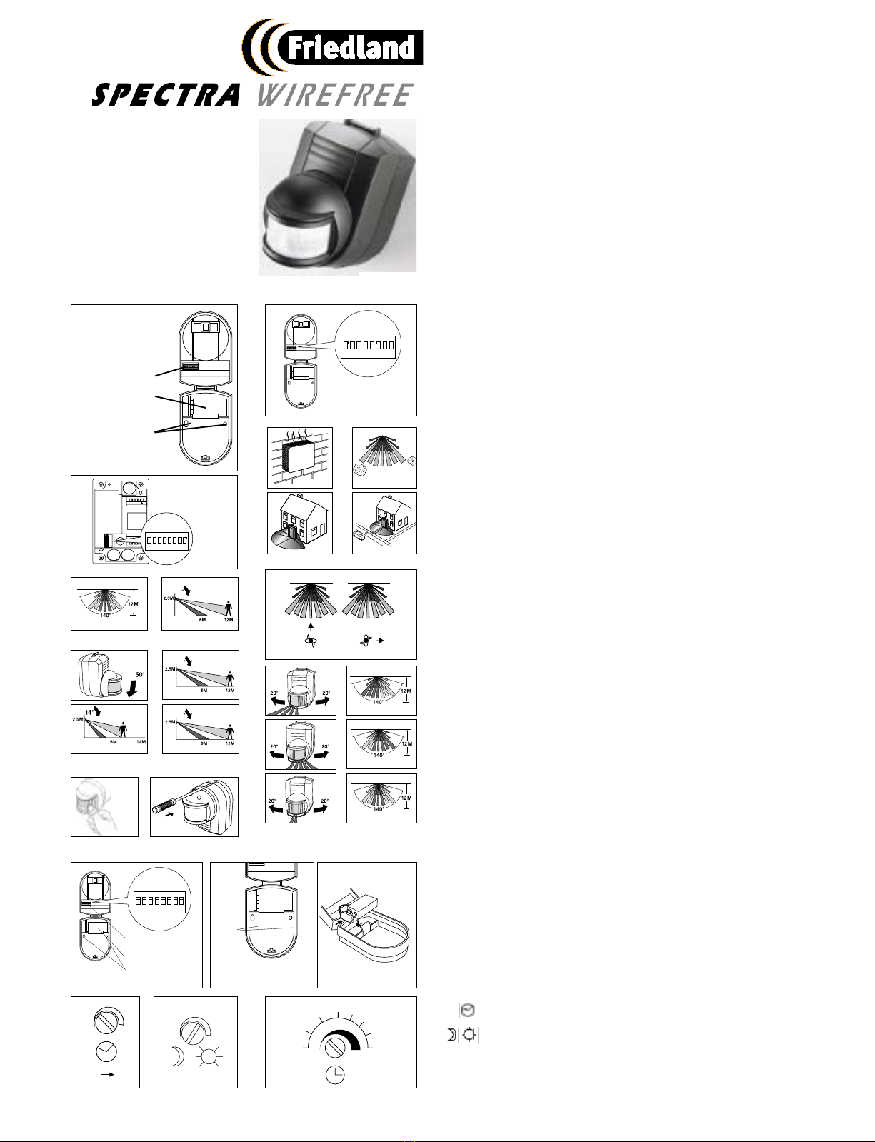
7. SETTING FOR AUTOMATIC OPERATION
Having completed the ‘walk test’ procedure, you can set the unit for automatic operation as follows:
■Adjust the TIME control to the setting you require. This controls the length of time the
security light stays on once activated, after all motion stops. The minimum time (control
set fully anticlockwise) is about 1 seconds; the maximum (control set fully clockwise) is
approximately 1 minutes. Set the control at whichever timing suits you between these
limits. (see fig 17 for approximate position of time settings).
N.B
. Remember that the
time you set relates to how long the lamp remains on after all motion stops. If someone triggers
your lamp it will remain on for as long as that person keeps moving in the detection area, then
continue to illuminate for the timing you have set after all motion stops.
■The ‘LUX’ control enables you to set the system to become active when a certain level
of darkness has fallen each evening. Set the LUX by turning the control fully anticlock-
wise, and wait until darkness begins to fall. When it is dark enough for you to want the
lamp to be operative, turn the LUX control clockwise slightly, move your hand slowly in
front of the PIR, turn the LUX control a little more and repeat the procedure until the light
activates. Leave the control set at this point.
9. CLEANING
Occasionally use a soft damp cloth to gently clean the PIR unit lens and plastic case. Take
care not to accidentally move the detector head.
8. BATTERY REPLACEMENT
The PP3 9 volt battery should provide the PIR Detector with around 18 months operation*.
When the battery is nearing the end of its life - about 30 days before failure - the PIR
Detector sends a message to the receiver, EACH TIME IT IS ACTIVATED so that THE
LIGHT BRIEFLY TURNS ON, THEN OFF THEN ON AGAIN IN QUICK SUCCESSION. THIS
NOTIFIES YOU TO CHANGE THE BATTERY.
As this ‘change battery’ message will not occur for some time and you may forget about it in
the future, we have included a reminder sticker which should be positioned in a prominent
place.
*Depending on the number of activations each day and the effect of low temperatures.
Set timing control back as it was and set
lux control to a ‘brighter’ setting than
before. The conditions may have generally
been too bright for the detector setting.
An intermittent problem may also be due
to occasional radio interference.
SOLUTION
Try repositioning the
detector to allow
a stronger signal to
reach the receiver.
SOLUTION
Try repositioning or
adjusting the angle or
direction of the PIR
SOLUTION
TEST OK
The PIR ‘view’ may be obscured by objects that
partially hide persons to be detected (e.g. posts,
pillars). The PIR position or sensor alignment
PROBLEM
PIR
Radio transmission is not being received due to
distance or obstructions or radio interference. Also
large metal objects (including vehicles) close to
the Detector Transmitter or Receiver Unit can
PROBLEM
PIR detects effectively but light doesn’t operate
■The PIR Detector may be suffering from false activation. Check this by
completely covering the Detector’s lens with a thick cloth, masking
tape or a piece of cardboard. This will stop the Detector ‘seeing’ any-
thing. If the Detector now lets the light switch off after the set time and
does not light it again, this indicates that the sensor has been picking
up movement within its range. Slightly adjust the position/angle of the
PIR Detector to solve the problem. Masking the area of the lens corre-
sponding to the location of the interference is another solution; and
since the PIR Detector is wirefree, even moving it to a new location is easy.
■The level of light at the Detector may be too low for the current photo-
cell LUX setting, activating the unit as though it were night-time. In nor-
mal daylight, adjust the LUX control slightly anticlockwise. Wait outside
the detection area until the light goes out, then re-enter it. If the PIR
Detector still activates, the LUX setting is still too high. Adjust and test
again until the unit stops activating the light.
■The PIR Detector operates by sensing temperature differences. On a
cold winter’s night, body heat stands out more contrastingly from the
surrounding cold conditions,
so the PIR Detector is more effective. On a warm night the contrast is
not so great, and the detector is less effective. For this reason, it may
be necessary to make seasonal adjustments to the PIR Detector.
■The PIR Detector may be suffering from false activation. Check this
by completely covering the detector’s lens with a thick cloth, masking
tape or a piece of cardboard.
This will stop the Detector ‘seeing’ anything. If the Detector now lets
the light switch off after the set time and does not light it again, this
indicates that the sensor has been picking up movement within its
range. Slightly adjust the position/angle of the PIR Detector to solve
the problem. Masking the area of the lens corresponding to the loca-
tion of the disturbance is another solution; and since the PIR detector
is wirefree, even moving it to a new location is easy.
■Wind may be activating the detector, due to where it is sited; try it in a
different location.
■Small animals and pets may be affecting the unit - try masking the
bottom half of the lens to stop the Detector from picking up low level
objects.
■Also check that the PIR Detector is not sensing movement from near-
by traffic or pedestrians. Alternatively, for the above problems, check if
a nearby wirefree system is operating with the same code. In this
instance the light would still operate if the detector lens was complete-
ly masked off or if the battery was removed - change the coding if
necessary.
Light stays on
continually at
night.
PIR Detector
activates the light
in daytime.
Detection range
varies from day to
day.
Light activates for
no obvious rea-
son, at random.
PROBLEM SOLUTION
GUARANTEE
Friedland Limited guarantee that should any defects in workmanship or materials occur in this product within 3
years from the date of purchase, it will be replaced provided it has not been dismantled, altered, or a repair
attempted. To comply with the 3 year guarantee, the installation and usage of the product must be in accor-
dance with the Technical Specification above and in particular, care should be taken to ensure the maximum
switching loads are not exceeded. The product should be returned to place of purchase along with this manu-
al, the purchase receipt and details of circumstances of the malfunction given. This undertaking is in addition
to the consumer’s statutory rights and does not affect these rights in any way.
Friedland Limited, Houldsworth Street, Stockport, Cheshire SK 6BP, England
PIR MOVEMENT DETECTOR
Transmitter range - Up to 0 metres
Detection range - Up to 12 metres
Angle of detection - 140°
Battery life - Minimum 18 months, at 8 activations per day and constant 1 °C
Battery type - PP3 (6LR61) 9 volt alkaline
Time on adjustment - 1 secs - 1 mins
Photocell adjustment - lux to daylight
Temperature
operating range - -20°C to +3 °C
11. TECHNICAL SPECIFICATIONS
If your wirefree system fails to work properly, complete the relevant test or tests which follow.
10. FAULT FINDING
PROBLEM
Confirm that bulb, mains supply, and battery are operating correctly.
Also ensure that the system codes in each unit match, and that the
PIR is within the operating range of 0 metres. If all these are OK,
Although this is most likely to be an incorrect lux setting, first con-
firm that there is not another cause by following the next step.
TEST THE SYSTEM’S OPERATION
Carry out a ‘Walk Test’ (see section 6). This allows you to check that the
PIR is functioning, when it is functioning and whether the Receiver is
…Ever
…At night
Light does not operate when it should…
…Intermittently

Other FRIEDLAND Security Sensor manuals

FRIEDLAND Spectra Plus L420N WHI User manual

FRIEDLAND

FRIEDLAND Spectra Plus L420N WHI User manual

FRIEDLAND Magnetic Contact User manual

FRIEDLAND

FRIEDLAND Magnetic Contact User manual

FRIEDLAND Spectra Plus L420N WHI User manual

FRIEDLAND

FRIEDLAND Spectra Plus L420N WHI User manual

FRIEDLAND SPECTRA WIREFREE 6500 User manual

FRIEDLAND

FRIEDLAND SPECTRA WIREFREE 6500 User manual

FRIEDLAND Spectra Lite L230N BLK User manual

FRIEDLAND

FRIEDLAND Spectra Lite L230N BLK User manual

FRIEDLAND SPECTRA Lite User manual

FRIEDLAND

FRIEDLAND SPECTRA Lite User manual

FRIEDLAND SPECTRA 140 User manual

FRIEDLAND

FRIEDLAND SPECTRA 140 User manual

FRIEDLAND D918S Libra+ User manual

FRIEDLAND

FRIEDLAND D918S Libra+ User manual

Popular Security Sensor manuals by other brands

tams elektronik RailCom RCD-2 manual

tams elektronik

tams elektronik RailCom RCD-2 manual

Honeywell Ex-Or MR2500D Installation and commissioning instructions

Honeywell

Honeywell Ex-Or MR2500D Installation and commissioning instructions

Teracom TSM400-4-CPTH user manual

Teracom

Teracom TSM400-4-CPTH user manual

SOMFY WireFree RTS Installer's guide

SOMFY

SOMFY WireFree RTS Installer's guide

Petzl ZIGZAG TECHNICAL NOTICE

Petzl

Petzl ZIGZAG TECHNICAL NOTICE

Rielta FOTON-21 installation guide

Rielta

Rielta FOTON-21 installation guide

PASCO PS-3219 BATTERY REPLACEMENT INSTRUCTIONS

PASCO

PASCO PS-3219 BATTERY REPLACEMENT INSTRUCTIONS

Dors 1170 user manual

Dors

Dors 1170 user manual

Elektrotechnik Schabus SHT 240 operating instructions

Elektrotechnik Schabus

Elektrotechnik Schabus SHT 240 operating instructions

NA-DE FD 8010 instruction manual

NA-DE

NA-DE FD 8010 instruction manual

Bosch DS9360 installation guide

Bosch

Bosch DS9360 installation guide

FORTEZA FMC 24 Pro General description manual

FORTEZA

FORTEZA FMC 24 Pro General description manual

Browan TABS TBMS100-915 Reference manual

Browan

Browan TABS TBMS100-915 Reference manual

STEIN COPIOUS Hot User instructions

STEIN

STEIN COPIOUS Hot User instructions

BEMKO SES65WH instructions

BEMKO

BEMKO SES65WH instructions

ITALIANA SENSORI 8137-ISR079 Installation, operation and maintenance manual

ITALIANA SENSORI

ITALIANA SENSORI 8137-ISR079 Installation, operation and maintenance manual

hager EE 810 Setup instructions

hager

hager EE 810 Setup instructions

STEINEL PROFESSIONAL HF 3360 manual

STEINEL PROFESSIONAL

STEINEL PROFESSIONAL HF 3360 manual

manuals.online logo
manuals.online logoBrands
  • About & Mission
  • Contact us
  • Privacy Policy
  • Terms and Conditions

Copyright 2025 Manuals.Online. All Rights Reserved.