New lift CBM2 User manual

CONTACTORLESS
BRAKE MODULE
MANUAL

Manual CBM2
Hersteller NEW LIFT
Neue elektronische Wege
Steuerungsbau GmbH
Lochhamer Schlag 8
82166 Gräfelng
Tel +49 89 – 898 66 – 0
Fax +49 89 – 898 66 – 300
Mail [email protected]
www.newlift.de
Serviceline Tel +49 89 – 898 66 – 110
Mail [email protected]
Erstausgabe 04.11.2021
Verfasser JW
Letzte Änderung 29.11.2023 / DOS
Freigabe AL
Hardwareversion CBM-5-89-21
Softwareversion V5.6.0.0
Dokumentnummer HB_CBM2_2023-11_v2.0_en
Copyright © NEW LIFT Steuerungsbau GmbH, 2023.
This manual is protected by copyright. All rights, including those of copying,
of reproduction, of translation and of modication, in whole or in part, are
reserved by the publisher.
No part of this description may be reproduced in any form or copied with an
electronic replication system without written permission.
Although great care has been taken in the production of texts and gures, we
cannot be held legally liable for possible mistakes and their consequences.
2

Manual CBM2 3
1 General 5
1.1 Abbreviations, characters and symbols used 5
1.2 Representations 6
1.3 Further information 6
1.4 How to contact us 6
2 Safety 7
2.1 Handling of electronic modules 7
3 Terminals 8
3.1 Connection 8
3.2 Pin Table 9
4 Conguration 10
4.1 Brakemonitoring 10
4.1.1 Contact-basedmonitoring 10
4.2 Motor-PTC 10
4.3 Rectiermode 10
4.4 Explanation of Inputs 11
4.4.1 DRIVE-Signal 11
4.4.2 BRAKE-Signal 11
4.4.3 EVAC-Signal 11
4.4.4 T-Signals 11
4.5 Explanation of Outputs 11
4.5.1 OK-Signal 11
4.5.2 Open-Signal 11
4.5.3 Test-Signal 11
4.6 Control process 12
4.6.1 Normal ride 12
4.6.2 Emergency Stop 12
4.6.3 Brake Test 12
4.6.4 Evacuation 12
4.7 EEPROM 13
4.7.1 Restore factory settings 13
4.8 Surge device Test 13
4.9 CANopen Bootloader 13
5 CANopen 14
5.1 Network Management 14
5.1.1 Node-ID 14
5.1.2 Bit Rate 14
5.1.3 NMT-RX-Events 14
5.2 Sync 14
5.3 Emergency 14
5.4 Heartbeat Producer 15
5.5 Object Dictionary 15
5.5.1 Daten-Types 15
5.5.2 Device Info 16

General
Manual CBM2 5
1 General
The CBM is a module that can control brake coils of all voltages (40-200VDC) and currents (up to 4A)
up to a power of 240VA without protection. It is type-tested according to DIN EN81-20. In addition, it
can perform brake test and evacuation (for machine roomless systems). In addition, other functions are
available, such as the connection of a motor PTC or brake monitoring. The function of the brake circuits
is monitored by a continuous current measurement.
1.1 Abbreviations, characters and symbols used
Abrreviation /
Symbol Meaning
CBM Contactorless Brake Module for elevatior
DRIVE Driving signal from the end of the safety chain
BRAKE Brake signal to open the brake
EVAK Evacuation signal for evacuation in the event of a fault in the system
TEST Test signals for brake test
CANopen CAN interface with CANopen protocol according to CiA Standard Draft
301
►
Activity symbol
Activities described after this symbol must be carried out in the given
order.
• Action step subordinate to the instruction
Safety-relevant information
This symbol is located in front of safety-relevant information.
Information notice
This symbol is located in front of relevant information.

General
6Manual CBM2
1.2 Representations
Representation Meaning
bold ›Terms of switches and control elements
›Input values
italic ›Captions
›References
›Terms of functions and signals
›Product names
bold italc ›Notes
Font LCD ›System messages of the controller
1.3 Further information
The following documents, among others, are available for the FST control system and its components.
›ADM Manual
›EAZ TFT.45.110.210 Manual
›EAZ-256 Manual
›EN81-20 Manual
›FPM Manual
›FST-2XT/s Manual
›FST-2XT MRL Manual
›FST Installation and Commissioning
›FST-3 MIPA
›GST-XT Manual
›LCS Manual
›RIO Manual
›SAM Manual
›UCM-A3 Manual
›Update-Backup-Analysis Manual
These and other current manuals can be found in the download area of our website under Service at
https://www.newlift.de/downloads.html
1.4 How to contact us
If, after referring to this manual, you still require assistance, our service line is there for you
Tel +49 89 – 898 66 – 110
Mail [email protected]
Mon. - Thurs.: 8:00 a.m. – 12:00 p.m. and 1:00 p.m. – 5:00 p.m.
Fr: 8:00 a.m. – 3:00 p.m.

Safety
Manual CBM2 7
2 Safety
All modules of the system may only be operated in a technically faultless condition and in accordance
with the intended use, safety and hazard awareness, observing the instructions, the applicable accident
prevention regulations and the guidelines of the local power supply company.
The safety guidelines of the FST manual and the FST Installation, Commissioning & Ccheck manual apply to
this product.
2.1 Handling of electronic modules
Electrostatic charge
►Leave the electronic module in its original packaging until installation to avoid damage.
►Before opening the original packaging a static discharge must take place!
To do this, touch an earthed metal part.
►Repeat the discharging process regularly while working on electronic modules!
►Provide all unused bus inputs/outputs with a terminator to prevent malfunctions.
Terminals
8Manual CBM2
3 Terminals
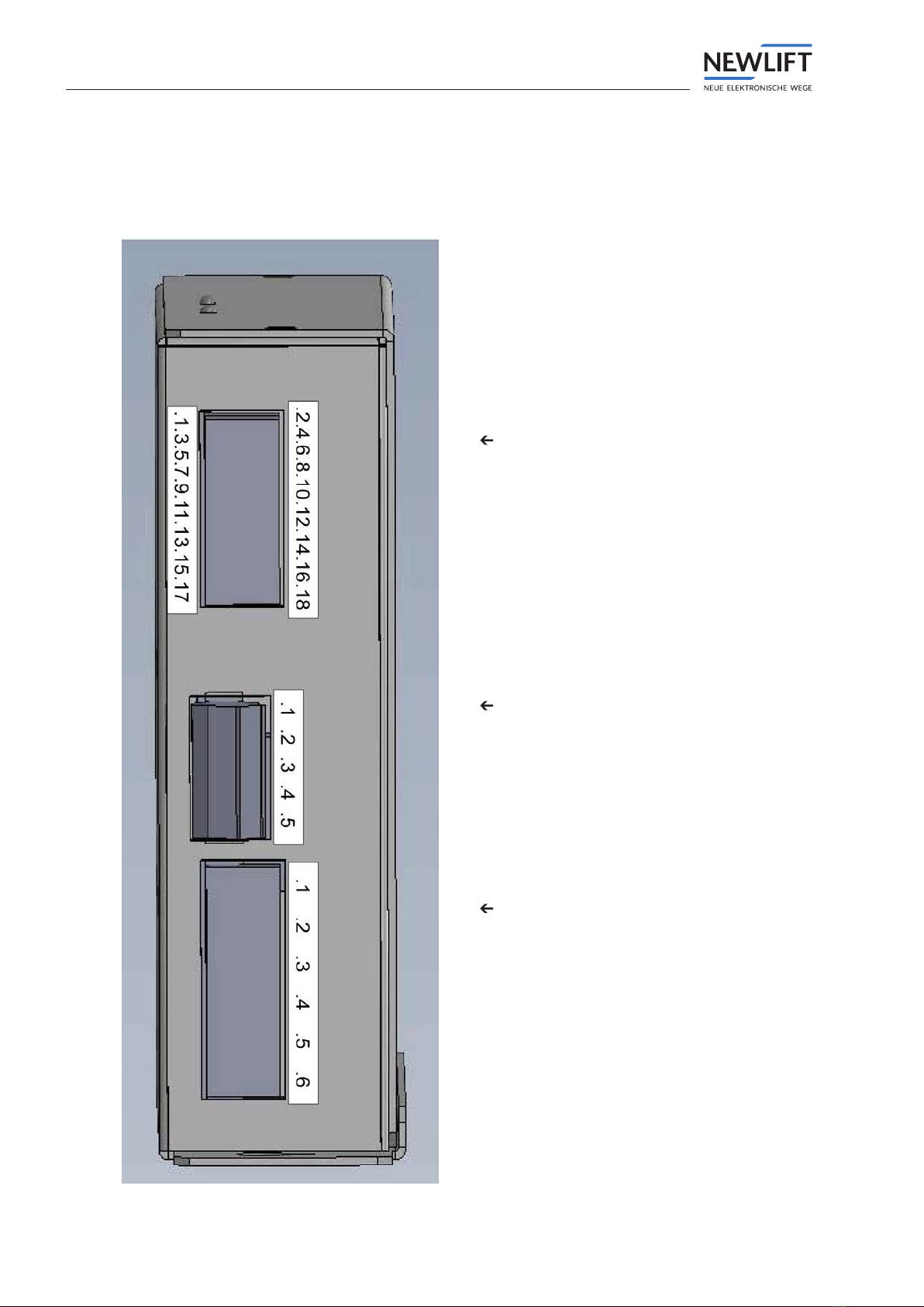
3.1 Connection
X3: IOs Connector PCB side: Phoenix
Contact MCDN 1,5/ 9-G1-3,81 Mating
Connector cable side: 2x Phoenix
Contact FMC 1,5/ 9-ST-3,81
X5: Power, Overvoltage-Test Connector
PCB side: Phoenix Contact CCA 2,5/
5-G-5,08MatingConnectorcableside:
PhoenixContactSMSTB2,5/5-ST-5,08
X4: DRIVE and Brake-Coils Connector
PCB side: Phoenix Contact GMSTBA
2,5/ 6-G Mating Connector cable side:
Phoenix Contact GMSTB 2,5/ 6-ST

Terminals
Manual CBM2 9
3.2 Pin Table
Clip Name Description Properties
X1.1
PE PowerSupply–230VAC
X1.2
LPowerSupply–230VAC
10ATräge
X1.3
NPowerSupply–230VAC
X1.4
Test Test Switch to simulate Overvoltage
spark
X1.5
Test
Test Switch to simulate Overvoltage
spark
X2.1
Drive
Drive-Signal–48-230VUC 24-230VUC
X2.2
Drive
Drive-Signal–48-230VUC
X2.3
B1+
Brake 1 Coil + 40-200VDC
X2.4
B1- Brake 1 Coil - 0V
X2.5
B2+ Brake 2 Coil + 40-200VDC
X2.6
B2-
Brake 2 Coil - 0V
X3.1
+24V DC
24V – Power Supply for In/Outputs
X3.2
0V(GND)
0V–PowerSupplyforIn/Outputs
X3.3
Brake
Brake-Signal Active High
X3.4
Evac
Evac-Signal Active High
X3.5
T1
T1-Eingang Active High
X3.6
T2
T2-Eingang Active High
X3.7
BM1
BM1-Signal Active High
X3.8
BM2
BM2-Signal Active High
X3.9
CBM_OK
CBMOKOutput(opencollector) Open Collector
X3.10
BRAKE_OPEN BrakeopenOutput(opencollector) Open Collector
X3.11
BRAKE_TEST TestactiveOutput(opencollector) Open Collector
X3.12
0V(GND)
Common pin for CAN-Interface
X3.13
CAN-H
CAN-H(CANopen) CANopen CiA 417
X3.14
CAN-L
CAN-L(CANopen)
X3.15
CAN-H
CAN-H(CANopen)
X3.16
CAN-L CAN-L(CANopen)
X3.17
PTC+ Motor PTC PTCnachDIN44081undDIN
44082
X3.18
PTC- Motor PTC

Configuration
10 Manual CBM2
4 Conguration
Unlike its predecessor, the CBM, the new CBM2 is congured exclusively via CANopen. It follows the
CiA 417 standard. The exact description of the data transfer takes place in CANopen CiA 417,
see „5 CANopen“, page 14.
4.1 Brake monitoring
The brakes are monitored via the brake monitoring contacts of the brakes.
4.1.1 Contact-based monitoring
Here contacts (NO or NC) must be connected to the inputs BM1 and / or BM2. These contacts must
also switch when the brake is activated. Otherwise, the error 0x19 (brake monitoring faulty) is
triggered.
4.2 Motor-PTC
The function of the motor PTC is automatically recognized the rst time it is switched on after resto-
ring the factory settings. If a PTC is then connected, it is activated. In that case, however, the PTC must
not have responded. If no PTC is connected, the function is deactivated. If the function is to be activa-
ted or deactivated during operation, the factory settings must rst be restored!
4.3 Rectiermode
If a voltage of 50V, 100V, 150V or 200V is set, the CBM2 operates in rectier mode. In this case, the
voltage is no longer generated via phase control, but the thyristors are permanently controlled over the
entire half-wave and only operate as a diode. With an input voltage of 230VAC, this results in an output
voltage of 51.75V, 103.5V, 155.25V or 207V. This mode can have a positive effect on the noise develop-
ment of the brake and also the CBMaus. If this function is not desired, a voltage increased or decreased
by 1V can be set.

Configuration
Manual CBM2 11
4.4 Explanation of Inputs
4.4.1 DRIVE-Signal
The DRIVE input can process voltages from 48-230VUC. This means that all common safety circuits
can be connected here. This signal opens two safety contacts in front of and behind the brake coil
and thus prepares the voltage supply for the brakes. If a gear brake is connected and congured, it is
directly energized with the DRIVE signal, since the brake on the gear must rst open.
4.4.2 BRAKE-Signal
The BRAKE signal opens a brake congured as a motor brake. A motor brake is usually mounted
directly on the motor shaft.
4.4.3 EVAC-Signal
The EVAK signal is used for evacuation in the event of a fault. It activates a different measurement of
the input voltage, as the evacuation can also be carried out with a UPS (VI-SY-333 or better) as the
power supply.
Normal travel is not possible when the EVAK signal is activated!
4.4.4 T-Signals
Either the brake test or the evacuation can be carried out with the signals T1 and T2.
In addition, the EEPROM can be re-initialized with the standard values by pressing T1 and T2 during
the boot process
See for details:
see „4.7.1 Restore factory settings“, page 13.
If only T1 is activated during the boot process, the CBM2 enters the bootloader and can receive new
rmware via CANopen.
If only T2 is activated during the boot process, stored errors are deleted.
Detailed description of the signal sequences can be found in:
see „4.6 Control process“, page 12.
4.5 Explanation of Outputs
4.5.1 OK-Signal
The OK output signals that the CBM is active and has no error. This output is only active when both
processors (control and monitor CPU) give their release.
4.5.2 Open-Signal
The open output signals an open brake.
4.5.3 Test-Signal
The test output signals an active brake test.

Configuration
12 Manual CBM2
4.6 Control process
4.6.1 Normal ride
›During normal driving, only the DRIVE and the BRAKE input are activated.
›DRIVE must be applied rst. In this case, if connected, the brake 3 is opened.
›Then BRAKE is applied (there must be no test signal). This opens brake 1 and 2.
›After the ride BRAKE is deactivated again.
›Then rst brake 1 and 2 close. Thereafter, brake 3 is closed.
›Now DRIVE must be deactivated again. The inputs DRIVE and BRAKE are checked with an ABC circuit.
This means that DRIVE must be activated before BRAKE and both signals must be deactivated before
reactivation!
4.6.2 Emergency Stop
In the event of an emergency stop, the DRIVE signal is deactivated rst. This means that all brakes are
applied immediately!
4.6.3 Brake Test
During the brake test, normal travel is rst initiated. If a test signal is already present during this (but-
ton has got stuck), error „0x1A - error inputs“ is set and normal travel is prevented. However, if a test
signal is applied after normal travel has been initiated, the associated brake is applied immediately. The
other brakes remain open.
The brake test is signaled directly to the elevator control via the test output. This must now ensure that
the torque is removed from the frequency converter. As a result, it will deactivate the BRAKE signal.
That is allowed for the brake test. The other brakes remain open anyway. The other brakes only apply
when the DRIVE signal is deactivated.
4.6.4 Evacuation
In order to carry out an evacuation, the EVAC signal must rst be activated. This changes the internal
control of the brakes, since the evacuation can also be carried out with a UPS. Since UPSs that do not
generate a pure sinusoidal voltage (VI-SY-333 or better) are also permitted, the phase control must be
adapted. The brakes are now controlled based on the previously saved operating current.
The DRIVE signal can now be activated. This already opens a transmission brake. The evacuation can
be activated by activating the test 1 and test 2 signals. This is carried out via the congured mode. If the
signals are deactivated again, the brakes are applied again..

Configuration
Manual CBM2 13
4.7 EEPROM
The EEPROM mainly stores data that is required for the CANopen functionality.
In addition, the operating currents of the individual brake coils are stored here. These are necessary to
carry out an evacuation. The default value for all brakes is the equivalent of 0.4A. If this value is still in
the EEPROM and normal travel is triggered, the current values of this normal travel are saved and used
in the following. An evacuation with a CBM in the factory setting without prior normal travel would
result in a current control to 0.4A per brake.
Correct evacuation is possible after a single normal trip.
4.7.1 Restore factory settings
►Switch ON CBM.
►During the start up
•Press buttons T1 and T2
or (if they are not present)
•set a jumper between X2.1 and X2.4 and X2.5.
Since an error occurs in the case at the same time:
►Turn OFF CBM.
►Release the buttons T1 and T2 or remove the jumper.
►Switch ON CBM.
After switching on again, the module is in the factory state.
4.8 Surge device Test
Either a button as a break contact or a wire bridge is connected to terminals X1.4 and X1.5. To test the
triggering of the overvoltage protection device at the voltage input of the CBM2, the connected button
can be pressed or the connected wire bridge can be removed. This causes an internal relay to drop out
at the input of the CBM2 and the output stage that generates the voltage for the brakes. This causes
the brakes to close and the CBM2 detects an undercurrent fault on the brakes. It is therefore no longer
possible to continue your journey.
4.9 CANopen Bootloader
The CBM2 is equipped with a CANopen bootloader that can perform rmware updates as described in
CiA 417. This means that, unlike the CBM1, rmware updates can now be carried out easily in the eld.
When using the CBM2 with the NEWLIFT FST2 lift controller, the rmware can be uploaded via the
FST2 using a USB stick. In addition, you can switch directly to the bootloader by pressing T1 during the
boot process of the CBM2. The CBM2 would then wait for rmware data via CANopen. However, a
specic protocol must be run for this, which is described in a separate manual.

CANopen
14 Manual CBM2
5 CANopen
With the integrated, isolated high-speed CAN ISO-11898 interface, a CANopen protocol according to
CiA 417 is integrated.
5.1 Network Management
The CBM is an NMT slave. An NMT master must make settings on the CBM in accordance with the
NMT protocol.
5.1.1 Node-ID
In the delivery state, the node ID is 125, which corresponds to a non-congured device according
to CiA 417. If an NMT master detects this, it must change the ID to 85-101, which are reserved for
manufacturer-specic IDs. The Node-ID can be changed in Object 0x2001.
5.1.2 Bit Rate
The bit rate is set to 250kbit / s in the delivery state.
5.1.3 NMT-RX-Events
The following NMT-RX events are implemented:
›1/0x01 – Start Node: sets the operational mode
›2/0x02 – Stop Node: sets the stop mode
›128/0x80 – Pre-Operational: sets the pre-operational mode
›129/0x81 – Reset: triggers a reset of the CBM
›130/0x82 – Reset Communication: triggers a reset of the CAN routines
By default, the CBM starts up in pre-operational mode. An NMT master must switch the CBM to opera-
tional mode.
5.2 Sync
The CBM is a SYNC consumer and can receive SYNC objects that were sent via the COB ID 0x080. This
mechanism is used for sending the TPDOs.
5.3 Emergency
In the event of a faulty SDO transfer or another error, an emergency message is sent. This is structured
as follows:
›Byte 0-1: CANopen Error Code
›Byte 2: CANopen Error Register
›Byte 3: -
›Byte 4: Manufacturer-specic error
›Byte 5: Manufacturer-specic error Detail
›Byte 6: Error generated during internal VCC not OK
›Byte 7: Error generated during emergency stop

CANopen
Manual CBM2 15
5.4 Heartbeat Producer
The CBM has a heartbeat endpoint that sends a heartbeat message. In the delivery state the interval
is 3000ms, but can be changed in the range of 500-20000ms. A heartbeat message can contain the
following information:
›0/0x00 - Bootup: CBM is booting
›4/0x04 - Stopped: CBM in Stop Mode
›5/0x05 - Operational: CBM in Operational Mode
›127/0x7F - Pre-Operational: CBM in Pre-Operational Mode
5.5 Object Dictionary
5.5.1 Daten-Types
›0x0001 – boolean
›0x0002 – integer8
›0x0003 – integer16
›0x0004 – integer32
›0x0005 – unsigned8
›0x0006 – unsigned16
›0x0007 – unsigned32

CANopen
16 Manual CBM2
5.5.2 Device Info
›0x1000 – device type; unsigned32;
»constant = 0x414D4243 („CBMA“) if application is running
»constant = 0x424D4243 („CBMB“) if bootloader is running
›0x1001 – error register; unsigned8; read only
›0x1002 – manufacturer status register; unsigned32; read only
›0x1003 – error code register; unsigned32; read only
›0x1009 – manufacturer hardware version; char[4](Ascii); constant
›0x100A – manufacturer software version; char[4](Ascii); constant
»Subindex 0 – Software version
»Subindex 1 – 0x07 GIT version string
›0x1017 – producer heartbeat time; unsigned16; read/write
»Values from 500-20000ms are accepted
* Demand from Master:
COB-ID: 0x600 + NodeID
cs: read=2, write=1
n: read=0, write=2
e: read=0, write=1
s: read=0, write=1
Index: 0x1017
Subindex: 0x0
Data: read=0, write=desired value
* Answer from CBM:
COB-ID: 0x580 + Node-ID
cs: read=2, write=3
n: read=2, write=0
e: read=1, write=0
s: read=1, write=0
Index: 0x1017
Subindex: 0x0
Data: read=actual value, write=0
›0x1018 – identity object
»Subindex 0 – Identity Index; unsigned8; constant = 4
»Subindex 1 – Vendor ID; unsigned32; constant = 0x0057454E
»Subindex 2 – Product Code; unsigned32; constant = 0x324D4243 (“CBM2“)
»Subindex 3 – Revision Number; unsigned32; constant = 0x000000xx where “xx” corresponds to
Revision number in SDO 0x3006 as integer
»Subindex 4 – Serial Number; unsigned32
5.5.3 RPDOs
›0x1400 – RPDO1 Parameter (Controlling)
»Subindex 0 – number of supported entries in this record (here 2); unsigned8; read only
»Subindex 1 – COB-ID used by PDO; unsigned32; read only
»Subindex 2 – transmission type; unsigned8; read only; default=255
RPDO1 is statically mapped to object 0x3016 which is the controlling via CANopen

CANopen
Manual CBM2 17
5.5.4 TPDOs
›0x1800 – TPDO1 Parameter (Errors)
»Subindex 0 – number of supported entries in this record (here 2); unsigned8; read only
»Subindex 1 – COB-ID used by PDO; unsigned32; read only
»Subindex 2 – transmission type; unsigned8; read/write; default=2 (1-240)
»TPDO1 is statically mapped to object 0x301F which is the status of the Errors
›0x1801 – TPDO2 Parameter (Outputs)
»Subindex 0 – number of supported entries in this record (here 2); unsigned8; read only
»Subindex 1 – COB-ID used by PDO; unsigned32; read only
»Subindex 2 – transmission type; unsigned8; read/write; default=1 (1-240)
»TPDO2 is statically mapped:
* Byte 0: Object 0x3014 which is the status of the Outputs
* Byte 1: Object 0x3017 which is the status of the Brake-Coils
›0x1802 – TPDO3 Parameter (Currents)
»Subindex 0 – number of supported entries in this record (here 2); unsigned8; read only
»Subindex 1 – COB-ID used by PDO; unsigned32; read only
»Subindex 2 – transmission type; unsigned8; read/write; default=1 (1-240)
»TPDO3 is statically mapped:
* Byte 0,1: Object 0x3001 which is current of Brake 1
* Byte 2,3: Object 0x3002 which is current of Brake 2
* Byte 4,5: 0 – Compatibility to CBM1
›0x1803 – TPDO4 Parameter (Currents of Brake fallback)
»Subindex 0 – number of supported entries in this record (here 2); unsigned8; read only
»Subindex 1 – COB-ID used by PDO; unsigned32; read only; 0x480 + Node
»Subindex 2 – transmission type; uint8; read only; default=0
»TPDO4 is statically mapped:
* Byte 0,1: Object 0x3001 which is current of Brake 1
* Byte 2,3: Object 0x3002 which is current of Brake 2
»TPDO4 is only transmitted if it is enabled in
* Object 0x2016 Subindex 10
* Object 0x2016 Subindex 1 = 3 and between brake switch off and safety chain opening!
5.5.4 Firmware Update
Firmware update processing; see CiA 302 Part 3: Conguration and program download
›0x1F50 – Program data
›0x1F51 – Program control
›0x1F56 – Program software identication current rmware version; same as 0x100A
›0x1F57 – Flash status identication
›0x6005 – Lock unlock parameters

CANopen
18 Manual CBM2
5.5.5 HerstellerspezischeSDOs
Bei allen SDO-Write-Transfers muss ein Reset durchgeführt werden, bevor die Änderung übernommen wird!
›0x2001 – Node-ID; unsigned8; read/write
Can be set from 85 to 101. A new uncongured Device is set to 125.
›0x2002 – Bitrate; unsigned8; read/write
»Bitrates implemented:
* 0 = 20kbit/s
* 1 = 50kbit/s
* 2 = 125kbit/s
* 3 = 250kbit/s (default)
* 4 = 500kbit/s
* 5 = 800kbit/s
›0x2003 – Lift-ID; unsigned8; read/write
Can be set from 0 (default) to 7
›0x2004 – Controlling Mode; unsigned8, read/write
»Read: 0x0X
»Write: 0x7300000X (the Ascii-Values of the character “s” need to be appended)
* Modes implemented:
0x0 = Controlling with IO (Conguration-Values extracted from DIP-Switches)
0x1 = Controlling with CANopen (Conguration-Values extracted from internal EEPROM)
›0x2011 – Voltages of the brakes; uint8; read/write
»Subindex 0: Number of entries = 2 (read only)
»Subindex 1: Voltage Brake 1
»Subindex 2: Voltage Brake 2
Voltages can be set from 40 to 200. A new uncongured Device is set to 0.
›0x2012 – Brake Modes; char[4]; read/write
»Subindex 0: Number of entries = 2 (read only)
»Subindex 1: Mode Brake 1
»Subindex 2: Mode Brake 2 Mode can be set to 0 (gear brake) or 1 (motor brake).
»Subindex 3: Connection Brake 1
»Subindex 4: Connection Brake 2
Connection can be set to 0 (only one coil) or 1 (two coils in series)
›0x2013 – Power reduction level of the brakes; char[4]; read/write
»Subindex 0: Number of entries = 2 (read only)
»Subindex 1: Reduction Level Brake 1
»Subindex 2: Reduction Level Brake 2
Reduction Level can be set from 50 to 100%. A new uncongured Device is set to 0.
›0x2014 – Power reduction time of the brakes; char[4]; read/write
»Subindex 0: Number of entries = 2 (read only)
»Subindex 1: Reduction Level Brake 1
»Subindex 2: Reduction Level Brake 2 Reduction Time can be set to 0, 3-10 or 255.0 means direct
Power Reduction, 255 means never reduce Power. A new uncongured Device is set to 0.
›0x2015 – Power Stage; char[4]; read/write
»Values implemented: 0 = Off 1 = On (default)
0x0 = OFF
0x1 = ON

CANopen
Manual CBM2 19
›0x2016 – Brake monitoring; read/write
»Subindex 0: Number of entries = 11 (read only)
»Subindex 1: uint8
* 0 = Off
* 1 = On, Contact-Type NO
* 2 = On, Contact-Type NC
* 3 = On, contactless
»Subindex 2: Counter Brake 1; uint16; Default: 100; Range: 20-1000
»Subindex 3: Current Offset Brake 1; uint16; Default: 50mA; Range: 5-500mA
»Subindex 4: Delay Monitoring after switch off; uint16; Default: 50ms; Range: 50-500ms
»Subindex 5: Counter Brake 2; uint16; Default: 100; Range: 20-1000
»Subindex 6: Current Offset Brake 2; uint16; Default: 50mA; Range: 5-500mA
»Subindex 7: Delay Monitoring after switch off; uint16; Default: 50ms; Range: 50-500ms
»Subindex 8: Start Tests; uint8; write only;
* 11 = leave brake 1 open after ride
* 12 = leave brake 2 open after ride
* 31 = leave Brake 1 closed
* 32 = leave Brake 2 closed
»Subindex 9: enables self-teach mode; writing a ‘1’ enables the self-teach mode; this measures the
counter values and adjusts the current offset for best results; as long as you read the value “1”
here, the self-teach mode is active; after self-teach mode has nished, the controller needs to read
the values to overtake them in the parameters! If counter values are 0 after self-teach Mode, self-
teaching was not possible! In that case parameters need to be adjusted manually or contactless
monitoring is not possible with these brakes. Contactless brake monitoring is switched off then
automatically; uint8
»Subindex 10: enables/disables sending of TPDO4 between brake switch off and safety chain ope-
ning; uint8
»Subindex 11: changes the interval of the sending of TPDO4 between 5 and 20ms; Default=10ms;
uint8
›0x2017 – Evacuation times; unsigned16; read/write
»Subindex 0: Number of entries = 2 (read only)
»Subindex 1: Evacuation pulse duration
»Subindex 2: Evacuation period duration
»Values can be set from 50-10000ms; Default: Pulse=200ms, Period=2000ms
When setting Strobe and Period to the same value, brakes are always open till evacuation is active!
›0x2019 – One Halfwave Mode; uint8; read/write
»Values implemented:
0x0 = Off
0x1 = On
›0x2020 – Delay switch off Gear-Brake; unsigned16; read/write
Can be set from 100 to 1000ms. Default is 1000ms
›0x2021 – Load-Check Pulse; uint16, read/write
Can be set from 50 to 1000ms. Default is 200ms. 0 switches off this function.
›0x2022 – CANopen Errors; uint8; read/write
»Values implemented:
0 = only Errors are transmitted which lead to shutoff (default)
1 = all Errors are transmitted
CANopen
20 Manual CBM2
›0x2023 – Delay Periods for MosFET-Tests; uint8; read/write
»Subindex 0: Number of entries = 2 (read only)
»Subindex 1: Delay periods HS-MF-Test, Number of periods for delaying the HS-MF-Test after
Switchoff and EEPROM-Write-Cycles
»Subindex 2: Delay periods HS-MF-Test, Number of periods for delaying the LS-MF-Test after the
HS-MF-Test
Can be set from 5 to 200. Default is 5(100ms).
›0x2024 – continuous contactless Brake monitoring; uint16, read/write
»Subindex 0: Number of entries = 8 (read only)
»Subindex 1: Counter Brake 1; Default: 0; Range: 20-1000; 0= continuous monitoring Off
»Subindex 2: Current Offset Brake 1; Default: 50mA; Range: 20-500mA
»Subindex 3: Delay Monitoring after switch on; Default: 2000ms; Range: 1000-5000ms
»Subindex 4: Counter Brake 2; Default: 0; Range: 20-1000; 0= continuous monitoring Off
»Subindex 5: Current Offset Brake 2; Default: 50mA; Range: 20-500mA
»Subindex 6: Delay Monitoring after switch on; Default: 2000ms; Range: 1000-5000ms
»Subindex 7: Delay for start Test after switch on; Default: 5000ms; Range: 2000-10000m
»Subindex 8: Start Tests; uint8; write only;
* 21 = close Brake 1 after delay
* 22 = close Brake 2 after delay
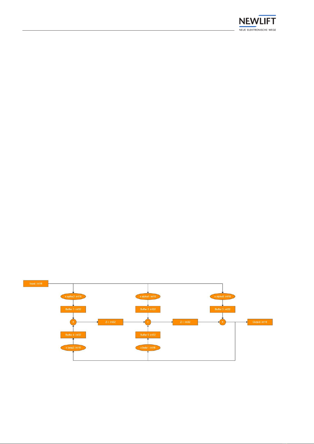
›0x2025 – IIR-Filter 2nd Order for Currents; Default: Butterworth with fg= 100 Hz and A= 1, 0
»Subindex 0: Number of entries = 6 (read only
»Subindex 1: Power of 2; uint8; Default: 10; Range: 6-12
»Subindex 2: alpha[0]; int16; Default: 47; Range: -32768 - +32767
»Subindex 3: alpha[1]; int16; Default: 94; Range: -32768 - +32767
»Subindex 4: alpha[2]; int16; Default: 47; Range: -32768 - +32767
»Subindex 5: beta[1]; int16; Default: 1339; Range: -32768 - +32767
»Subindex 6: beta[2]; int16; Default: -504; Range: -32768 - +32767
»Filter structure
Table of contents
Other New lift Control Unit manuals


Popular Control Unit manuals by other brands


Sagem
Sagem MO300 M2M Application note

VAT
VAT 650 Series Installation, operating, & maintenance instructions

Siemens
Siemens WATCHDOG-Modul ET 200iSP Product information

Grundfos
Grundfos CIM 200 Functional profile and user manual

LOXONE
LOXONE Miniserver Go quick start guide

Cumberland
Cumberland SP-MODULE user manual

Elkron
Elkron IT500CLOUD user manual

Emerson
Emerson Anderson Greenwood 727 Series Installation and maintenance instructions

Espressif Systems
Espressif Systems ESP32-S2-SOLO-2 user manual

Peak
Peak PCAN-MicroMod FD Digital 1 user manual

Gemu
Gemu 410 Installation, Operating and Maintenance Instructions for the Installer and the User

Beckhoff
Beckhoff EK9500 Documentation