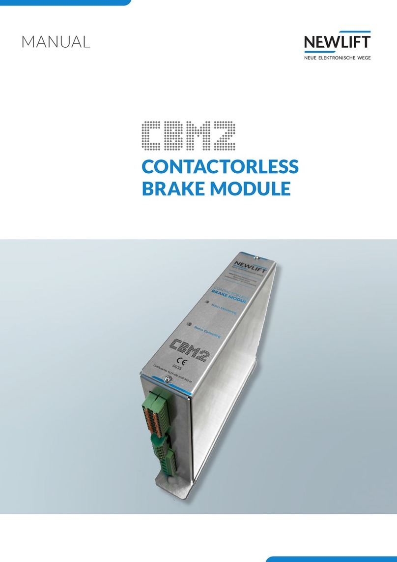
New lift FST-3 Guide

Lift control module, safety module and safety system
INSTALLATION, COMMISSION-
ING & CHECK MANUAL

Installation, commissioning & check manual – FST-3
Manufacturer NEW LIFT
Neue elektronische Wege
Steuerungsbau GmbH
Lochhamer Schlag 8
82166 Gräfelng
Phone +49 89 – 898 66 – 0
Fax +49 89 – 898 66 – 300
E-mail [email protected]
www.newlift.de
Service line Phone +49 89 – 898 66 – 110
E-mail [email protected]
First edition 23.05.2023
Author AL/AME
Last change 22.11.2023 / DOS
Release 22.11.2023 / AL
Hardware version S2: V1.02 / FST-3: V1.1
S2 software version V2.200-0022
FST software version V180
Software signature S2 0x67EC4006
Document number S2.28
Document version MIPA_FST-3_2023-11_EN
Copyright © NEW LIFT Steuerungsbau GmbH, 2023.
This manual is protected by copyright. All rights, including those of copying,
of reproduction, of translation and of modication, in whole or in part, are
reserved by the publisher.
No part of this description may be reproduced in any form or copied with an
electronic replication system without written permission.
Although great care has been taken in the production of texts and gures, we
cannot be held legally liable for possible mistakes and their consequences.

Installation, commissioning & check manual – FST-3 3
Inhalt
1 About this manual 8
1.1 General 8
1.2 Abbreviations, characters and symbols used 8
1.3 Notation 9
1.4 Further information 10
1.5 How to contact us 10
2 Safety 11
2.1 Safety regulations 11
2.1.1 Qualicationsoftheliftengineer 11
2.2 Residual dangers and protective measures 11
2.3 Basic safety principles 13
3 Safety functions 16
3.1 Overview of the safety functions 16
3.1.1 Overspeed (pre-triggering) 18
3.1.2 Overspeed (speed limiter) 18
3.1.3 Deceleration control circuit 18
3.1.4 Emergency end switch 18
3.1.5 Door bypass 19
3.1.6 Inspection end switch 19
3.1.7 Unintended movement with opened doors 19
3.1.8 Access door monitoring 20
3.1.9 Resetting the access door monitoring 20
3.1.10 Pre-triggered stopping system 20
3.1.11 Loss of traction 21
3.1.12 Prevention of normal operation (bypass) 22
3.1.13 Inspection switch 22
3.1.14 Monitoring the inspection buttons 22
3.1.15 Auxiliary mode switch 22
3.1.16 Mechanical equipment (folding supports) 23
3.1.17 Temporary protected space 23
3.1.18 Acceleration monitoring 23
3.1.19 Installation mode preventing normal operation 24
3.1.20 Monitoring the inspection and auxiliary speed 24
3.2 Basic safety principles 24
4 Commissioning table 26
5 Required knowledge 29
5.1 Denitionsofterms 29
5.2 Switching installation and teach mode on and off 30
5.2.1 Installation mode 30
5.2.2 Teach mode 30
6 System properties 31
6.2.1 Technical properties – FST-3 32
6.2.2 Technical properties – S2 32

4Installation, commissioning & check manual – FST-3
7 User interface of FST-3 controller 33
7.1 Keypad functions 34
7.1.1 When switching on 34
7.1.2 Main screen 34
7.1.3 Main menu and test menu 35
7.1.4 Error list 36
7.1.5 Information page 36
7.1.6 Frequency inverter with DCP interface 36
7.1.7 Guide 36
7.2 S2 guide 36
7.2.1 Emergency mode monitor (NBM) 40
7.3 TFT display and messages 42
7.3.1 Main screen 42
7.3.2 Line A – Safety circuit messages 42
7.3.3 Line B – State messages 43
7.3.4 Line C – Status messages 45
7.3.5 Line C - Diagnostic messages 46
7.3.6 Line D - Drive mode messages 47
7.4 Information texts 48
7.4.1 Information page 53
7.5 LEDs 54
7.5.1 LEDs of FST-3 54
7.5.2 LEDs of S2 55
8 Installation work 56
8.1 Installation procedure 56
8.2 Installing and wiring the system 56
8.2.1 Checking the delivery contents 56
8.3 Control cabinet 57
8.3.1 Checking the general requirements of the lift system 61
8.4 Travelling cable 62
8.5 Car components 63
8.5.1 Car top box 63
8.5.2 Car components 63
8.5.3 FPM-1 65
8.5.4 Connecting the LON bus 65
9 Installation and commissioning 68
9.1 Connecting the lift components to the S2
(commissioning step 1) 68
9.2 Preparing to switch on the controller 70
9.2.1 Switching on the FST-3 (S2) controller 70
9.2.2 Checking the safety circuit 70
9.3 Installation mode, teach mode and S2 error reset 71
9.3.1 Switching installation mode on/off 71
9.3.2 Switching teach mode on/off 72
9.3.3 Procedure for S2 error reset 72
9.4 Checking important system functions 72
9.4.1 Checking system settings of the FST (commissioning step 2) 72

Installation, commissioning & check manual – FST-3 5
9.4.2 Checking installation mode (commissioning step 3) 73
9.4.3 Checking system speed (commissioning step 4) 73
9.4.4 Performing a reset and activating the safety system 75
9.4.5 Installation drive without sensor 76
9.4.6 Checking auxiliary mode control (commissioning step 5) 76
9.4.7 Checking SHK relay triggering (commissioning step 6) 77
9.4.8 Checking the traction (commissioning step 7) 77
9.4.9 Checking SBR relay triggering (commissioning step 8) 77
9.4.10 Checking the folding supports protected space version (commissioning step 9) 78
9.4.11 Checking the inspection control (commissioning step 10) 79
9.4.12 Installing the position system (commissioning step 11) 80
9.4.13 Installing the magnetic tape 80
9.4.14 Installing the magnetic tape with magnetic tape holder 81
9.5 Installing the sensor 87
9.5.1 Connecting the sensor and switching on the control system 89
9.5.2 Sensor LEDs 90
9.5.3 Checking the position system (commissioning step 12) 91
9.5.4 Installation check 91
9.5.5 Checking a loss of traction (commissioning step 13) 92
9.5.6 Teachingendswitchesandendoors(commissioningsteps14and15) 92
9.5.7 Checking inspection end switches (commissioning step 16) 95
9.5.8 Checking access monitoring (commissioning step 17) 96
9.5.9 Carrying out calibration drive 97
9.5.10 Checking positioning accuracy 99
9.5.11 Checking the trigger speed (commissioning step 18) 100
9.5.12 Checking deceleration monitoring (commissioning step 19) 102
9.5.13 Checking the pre-triggered stopping system protected space version (commissioning step 20) 104
9.5.14 Checking emergency end switches (commissioning step 21) 104
9.5.15 Checking the bypass switch (commissioning step 22) 105
9.5.16 Setting the door zone length (commissioning step 23) 106
9.6 Teachingandcheckingtheoors(commissioningstep24) 106
9.6.1 Levelling adjustment 107
9.6.2 Level adjustment via FPM-1 or FPM-2. 107
9.6.3 Checking unintended movements (UCM) (commissioning step 25) 109
9.7 Setting control options 110
9.7.1 Optimising re-levelling 110
9.7.2 Crawl drive 110
9.7.3 Door times 111
9.7.4 Password 112
9.8 Test actuation and checking monitoring functions in accordance with EN81 113
9.9 Emergencycalllter 119
9.10 Creating & loading a bacbcp 119
9.11 LONmoduleconguration 120
10 Technical data 127
10.1 FST-3 control module 127
10.1.1 General 127
10.1.2 Dimensions 128
10.1.3 FST-3 jumpers 131
10.1.4 Microfuses 131

6Installation, commissioning & check manual – FST-3
10.1.5 FST-3 terminal strips and sockets 131
10.2 S2 safety module 136
10.2.1 General 136
10.2.2 Dimensions 137
10.2.3 S2 terminal strips and sockets 140
10.3 FSM-2 car top control module 142
10.3.1 FSM-2 jumpers 143
10.3.2 FSM-2 terminal strips and sockets 143
10.4 FPM-1 car operating panel module 148
10.4.1 FPM-1 jumpers 149
10.4.2 FPM-1 terminal strips and sockets 150
10.5 FPM-2 152
10.5.1 FPM-2 jumpers 152
10.5.2 FPM-2 terminal strips and sockets 153
10.6 EAZ-256/40 and EAZ256/64 156
10.6.1 FPM-2 jumpers 156
10.6.2 Connection properties 157
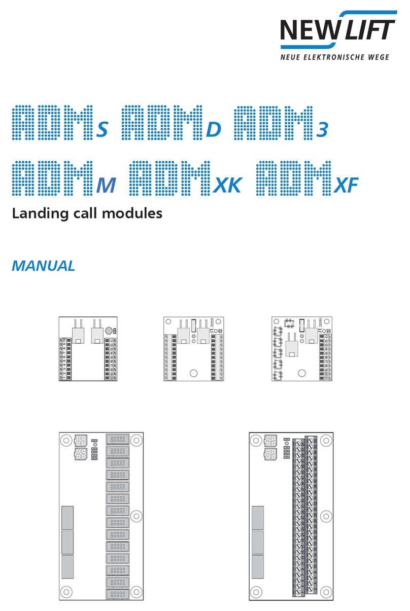
10.7 ADM-S and ADM-D 158
10.7.1 Connection properties 158
10.8 ADM-3 159
10.8.1 Connection properties 159
10.9 ADM-XF and ADM-XK 161
10.9.1 Connection properties 161
10.9.2 ADM-XF and ADM-XK jumpers 161
10.9.3 ADM-XF and ADM-XK terminal strips and sockets 162
11 Commissioning the GST-XT 163
11.1 General 163
11.2 Commissioning steps 163
11.2.1 Switch off FST- and GST-XT controllers 164
11.2.2 Establishing bus connections 164
11.2.3 Checking basic settings in the FST controllers 165
11.2.4 Checking basic settings in the GST-XT controller 168
11.2.5 Check the status of the systems 168
11.2.6 LoadingFSTcongurationdataintheGST-XT 168
11.2.7 Testing group function 169
12 Menu tree 170
12.1 General 170
12.2 MAINMENU-Conguration/Installation/S2-System 172
12.3 MAIN MENU - Positioning/Global 173
12.4 TEST MENU 173
13 Event and error messages 174
13.1 Event messages 174
13.2 Error messages 178
14 Further explanations 195
14.1 Setting the trigger speed 195

Installation, commissioning & check manual – FST-3 7
14.2 Shortened buffers at shaft end 195
14.3 Teaching positions in the shaft 196
14.4 Setting the access monitoring 196
14.5 Replacing hardware components 196
14.6 Capacitive coupling 198
15 Checks 201
15.1 Rupture valve test instruction 203
16 Emergency escape 205
16.1 S2 safety functions during evacuation operation 205
16.2 Protective measures for unforeseeable events 206
16.3 Emergency escape procedure with S2 safety system 206
16.4 Emergency escape procedure without S2 safety system 206
16.5 Diagnostics interval 207
17 Technical data – Sensor, magnetic tape and bracket 208
17.1 Marking 208
17.2 Technical data - Sensor 210
17.2.1 Pin assignment for D-sub connector, LIMAX3R/D9M sensor 212
17.2.2 Sensor bracket 212
17.3 Technical data - Magnetic tape 213
17.4 Technical data – Magnetic tape bracket 214
18 Functions and properties of switches, sensors and actuators 215
18.1 Sensor combination 215
18.2 Logic circuit (S2 monitoring) 217
18.3 Combination of actuators and sensors 218
18.4 Spare parts list 220
19 Maintenance, servicing, repairs 221
20 Overview wiring diagram 222
21 Change history 223
22 Certicates 224
22.1 Declarations of conformity 224
22.2 Typeexaminationcerticate 226
23 Index 242

About this manual
8Installation, commissioning & check manual – FST-3
1 About this manual
Please read this manual carefully before installing and commissioning the FST-3 controller. The safety
regulations must be observed throughout (see 2.1 Safety regulations, page 11). Operation of the FST-3
controller is briey explained in Chapter see 7 User interface of FST-3 controller, page 33.
1.1 General
This manual will help you during installation and commissioning of the FST-3 controller and its
components.
The installation, commissioning and maintenance manual contains important information for safe and
proper installation and commissioning of the FST-3 controller.
Following these instructions will help to:
› prevent danger,
› avoid repair costs and downtime,
› increase the reliability and lifespan of the FST-3 controller and of the lift system.
Local, national and on-site regulations regarding health and safety and protection of the environment
must be taken into account in addition to this installation and commissioning manual.
This manual only describes the assemblies of the lift system delivered by NEW LIFT. For information
about components of the lift system that were not manufactured and supplied by NEW LIFT, please
refer to the respective user information supplied by the manufacturer or supplier.
1.2 Abbreviations, characters and symbols used
Symbol /
abbreviation Meaning
►Delivery condition
Settings that are supplied as standard are marked with an asterisk .
System stop
Marks settings requiring a system stop in case a change becomes neces-
sary. The FST controller displays the text Lift must be stopped to
change the value. OK? If you wish to change the value, conrm with
YES, if you do not wish to change the value or wish to change it later, then
conrm with NO.
°
Re-start
Marks settings that only become active after a re-start of the FST-3 or of
the components.
►Operational instructions
Perform the tasks that follow this symbol in the specied order.
+Key combination:
Press the linked keys simultaneously.
PPower
IInput
OOutput
Llow active

About this manual
Installation, commissioning & check manual – FST-3 9
Hhigh active
Safety-relevant information
This symbol is located in front of safety-relevant information.
Information notice
This symbol is located in front of relevant information.
This symbol alerts you to a conguration-dependent test step.
1.3 Notation
Notation Meaning
Bold › Designations of switches and actuators
› Input values
Italics › Captions
› Cross references
› Designations of functions and signals
› Product names
Bold italics › Remarks
LCD font › System messages of the controller

About this manual
10 Installation, commissioning & check manual – FST-3
1.4 Further information
The following documents, among others, are available for the FST-3 controller and its components:
› LIMAX33RED operating instructions
› ADM manual
› EAZ TFT.45.110.210 manual
› EAZ-256 manual
› EN81-20 manual
› FPM manual
› FST-3 manual
› Update backup analysis manual
› GST-XT manual
› LCS manual
› RIO manual
› SAM manual
These and other current manuals can be found in the download area of our website at
https://www.newlift.de/downloads.html
1.5 How to contact us
If, after referring to this manual, you still require assistance, our service line is there for you:
Phone +49 89 – 898 66 – 110
E-mail [email protected]
Mon. - Thurs.: 8:00 a.m. – 12:00 p.m. and 1:00 p.m. – 5:00 p.m.
Fr: 8:00 a.m. – 3:00 p.m.

Safety
Installation, commissioning & check manual – FST-3 11
2 Safety
2.1 Safety regulations
All important safety regulations are summarised in this chapter. These safety instructions must always
be adhered to during all work on the installation.
All persons performing installation, commissioning, maintenance as well as repair work on the FST-3
(S2) safety system must always read this chapter, among others, and implement the requirements
specied therein.
2.1.1 Qualicationsoftheliftengineer
The lift engineer must:
› be over 18 years of age (exception: apprentices who are over 16 years of age and are permanently
supervised by an engineer qualied for training apprentices).
› have rst aid training,
› have theoretical and practical knowledge of regulations and measures for the prevention of re and
explosions in his work area,
› be able to identify, avoid and rectify all dangers that might occur during his work in the shaft and in the
operating rooms,
› be able to identify and rectify all irregularities and faults that might occur during installation and opera-
tion of a lift system,
› have theoretical and practical knowledge of operating principles and requirements of electric controls
and drive systems.
All installation and commissioning work on electric and electronic components of the FST-3 controller
must be performed by or supervised by a qualied electrician.
A qualied electrician has appropriate training and knowledge of regulations that allow him to judge
the quality of the work performed and identify possible dangers (DGUV regulation 3).
2.2 Residual dangers and protective measures
Danger for persons
The following shall always apply during all work on the installation:
Danger to life! Do not touch live parts while working on electrical equipment.
►Before starting work, make sure the system is off circuit.
►Only carry out any installation work on electrical components when these are switched off and in an
unpowered state.
►Only use insulated tools when working on electrical system components.
Risk of injury when lifting or moving the control cabinet if it falls down or tips over.
►Only transport and lift the control cabinet with suitable equipment (lift truck, hoisting gear etc.).
►All workers must be trained in using these aids and must observe all applicable special regulations to
avoid accidents.
Falling parts or parts protruding into the shaft. Risk of serious injury or death.
►Block the shaft access points.
►Before beginning installation work, remove all foreign parts and assembly aids that are not required
from the shaft.
Electrical hazard, leaking gas or water due to pierced supply lines. Risk of serious injury or death.

Safety
12 Installation, commissioning & check manual – FST-3
►Make sure no supply lines are in the installation location before starting any installation work.
Danger of falling! Lift engineers and unauthorised persons can fall down the shaft. Risk of serious injury or
death.
►Block the shaft access points.
►Use suitable protection (e.g. safety harnesses, scaffoldings) when working on or in the shaft.
Danger of crushing due to intentional or accidental car movement. Risk of serious injury or death.
►Block the shaft access points.
►Before starting any work, make sure that there are no persons in the shaft or in the vicinity of mov-
ing parts of the drive.
►Prevent unauthorised operation of the controller.
Risk of material damage
The following shall always apply during all work on the installation:
Electrostatic charging
►Keep the electronic assembly in its original packaging until installation.
►Before opening the original packaging, a static discharge must be performed. To do this, touch a
grounded piece of metal.
►During work on electronic assemblies, periodically perform this discharge procedure.
Electronic assemblies are destroyed by defective, interchanged or incorrectly mounted connectors, short-cir-
cuiting or excess voltage.
►Check plugs for mechanical damage.
►Never change pre-assembled connectors or cables.
►Only connect loose or torn off wires according to wiring diagram details if this is possible on site
(suitable material and tools must be available).
►Pay attention to coding pins and latch lugs.
Failure of the safety functions!
Sources of interference in the operational environment can lead to a failure of the FST-3 safety system.
►Do not use the FST-3 safety system in explosive or corrosive environments.
►Do not install the system near sources of interference exhibiting strong inductive or capacitive inter-
ference or electrostatic elds.
Dangerous electrical voltage!
When installing the FST-3 in the control cabinet, live parts may be touched.
►All work on the electrics may only be performed by a qualied electrician.
►Disconnect the system and all components from the voltage supply before commencing with instal-
lation or wiring work.
►Provide ne-wire cables and stranded wires with ferrules.
►Check all sockets, terminals and plug connections prior to switching on.
Danger of falling! Risk of serious injury or death!
Until commissioning is complete, conventional safety precautions are wholly or partially out of operation.
►Dene suitable contingency measures during project planning.
►Make sure that these contingency measures are available and installed until commissioning on site.
►Never congure the system via remote access – only on site.
►Be aware of the active/inactive safety functions at all times during commissioning.
►Check safety-related parameters are working properly each time after conguration is performed or
changes are made.

Safety
Installation, commissioning & check manual – FST-3 13
►Document all commissioning steps and every subsequent change to the system.
►Check all new or modied settings for plausibility through the FST-3 safety system.
Danger of falling! Risk of serious injury or death!
In installation mode, the position-dependent safety functions – especially the safety function for monitoring
speed and acceleration – are out of operation until either one of the four end switches has been taught or the
tape switch has been connected.
►Be aware of the active/inactive safety functions at all times during commissioning.
►On completion of installation work, deactivate installation mode.
2.3 Basic safety principles
During commissioning, the installation of the FST-3 safety system represents a high risk for the lift
engineer, because the system can only offer a low level of safety in principle. In particular, the moni-
toring of the nominal speed (safety brake during Over- speed) is not available. During the rst steps of
commissioning, the lift engineer bears a lot of responsibility, especially for his/her own safety:
Installation mode safety risk:
› In installation mode, the position-dependent safety functions are out of operation until either one of
the four end switches has been taught or the tape switch is connected.
› In installation mode, end switches that have not been taught are not active.
Consequently, it is ensured that the lift engineer can rst move the car for the purpose of tape installa-
tion in the shaft and subsequently, during the teaching of the end switches, enjoys the greatest possible
safety that the system can offer.
Installation and teach mode differentiation:
Installation mode of the FST-3 safety system can be activated or deactivated in combination with a
certain parameter activity in a time-limited conrmation action by means of the auxiliary mode control.
Installation mode must only be accessible to one lift engineer who is aware of his/her responsibility and
is able to correctly assess risk and, where necessary, take contingency measures. In installation mode,
the car can only be moved using the auxiliary mode and inspection control.
Teach mode of the FST-3 safety system can also be activated or deactivated in combination with a
certain parameter activity in a time-limited conrmation action by means of the auxiliary mode con-
trol. It is much less critical than installation mode. All safety functions are in operation. Only the oor
positions and the door zone length can be modied. After activating the teach mode, normal operation
of the lift by passengers is prevented by the FST (landing calls are blocked). The car can be moved using
the auxiliary mode and inspection control or by car calls.
The following basic safety principles apply throughout the entire commissioning phase:
› The lift engineer must know which safety functions are active at every point in time during commis-
sioning. Consequently, the installing engineer can assess whether additional measures are necessary.
› Safety-related parameters must be tested following conguration or modication before safety can be
guaranteed.
› All commissioning steps and every subsequent change must be documented by the lift engineer. An
appropriate template is printed in the user documentation.
› The system must not be congured via remote access (EN81-50, B.1, no.7). In other words, the lift
engineer must be on site to perform conguration changes.
› All changed settings must be checked by the FST-3 safety system for plausibility before becoming
active.
General
› The instructions of the lift manufacturer and the instructions in this manual must be followed during
installation and commissioning of the lift system.
› The shaft must be secured against unauthorised trespassing during installation and commissioning.

Safety
14 Installation, commissioning & check manual – FST-3
› Assemblies, devices and cables must be installed and fastened securely and permanently.
› Loads must be moved with suitable aids (lift trucks, hoisting gear etc.).
› Sharp and pointed tools or other potentially dangerous objects may only be carried along in clothing if
suitable protective measures have been taken to rule out any danger.
› Alcohol and drugs must not be consumed before and during installation and commissioning.
Documentation
› A copy of the installation and commissioning manual must be available to the lift engineer at the time of
installing and commissioning the FST-3 safety system and its components.
› A copy of the installation and commissioning manual and the wiring diagrams must be kept in the con-
trol cabinet at all times after installation.
› The supplied wiring diagrams of the FST-3 safety system are binding. Changes must only be made after
consulting NEW LIFTand must be documented in writing on the system.
› The factory test logs of the FST-3 safety system remain with NEW LIFT.
Electricity
› Regulations for installing and operating electrical equipment (VDE 0100) and regulations of local utili-
ties must be followed.
› The specied distances between different electrical assemblies must be controlled and maintained.
› All installation work must be carried out with the system shut down and off circuit.
› All cables and wires must be installed with sufcient strain relief.
› The neutral wire and earth wire must be routed separately.
› The control cabinet must be supplied with a clockwise rotary eld.
Working in the shaft
› Any work in the shaft requires perfect and permanent communication between the supervisor on the
FST-3 safety system in the motor room and the workers in the shaft.
› Components in the shaft must be arranged or secured in such a way that persons accessing the shaft
for inspection, maintenance or repair purposes are not in danger.
› The maximum load of the lift system must not be exceeded.
› The specied overruns of the emergency end switches in relation to the speed must be observed.
› The emergency installations must not be activated during normal operation.
› All emergency installations and braking systems must be checked for troublefree operation and all
shaft entrances closed off before beginning work.
› Installation and operation are prohibited if other persons could be in danger.
› Workers must be secured against falling.
› In case of any work interruptions, the car must be moved to the lowest stop position, the controller
switched off and the power supply (e.g. UPS) permanently disconnected.
Personal safety equipment of the lift engineer
› Eye protection
› Safety boots
› Protective helmet
› Safety harness
› Clothing suitable to the ambient conditions of the installation location
› Jewellery, watches and similar items may not be worn; a hair net must be used if applicable.
Handling electronic assemblies
› Leave electronic assemblies in their original packaging until installation.
› Touch a grounded piece of metal prior to opening the original packaging to prevent damage from static

Safety
Installation, commissioning & check manual – FST-3 15
charges.
› All bus inputs and outputs not in use must be equipped with a terminal resistor (terminator).
Waste disposal
› All packaging material must be disposed of in an environmentally acceptable manner; paper, plastic,
metal, electronic assemblies etc. must be recycled

Safety functions
16 Installation, commissioning & check manual – FST-3
3 Safety functions
The S2 safety system may only be operated with an FST-3 lift controller from NEW Lift Neue elek-
tronische Wege Steuerungsbau GmbH. This is sometimes referred to in this document as FST.
3.1 Overview of the safety functions
The S2 safety system can be used for the following functions:
No.
Inputs
Safety function
Standard
Actuator
SIL
FST fault reset / test menu*
S2 reset *
SG reset / S256*
SK reset / 256*
No reset required*
1VTrip position
(EEPROM)
Overspeed speed
(pre-triggering)
EN 81-20, 5.6.2.2.1.6 a) SHK 2 X
2VTrip position
(EEPROM)
Overspeed speed
speed limiter
EN81-20, 5.6.2.2.1.1 a) SBR
SHK
3 1 2 2
3 Position
shaft image
Deceleration control
circuit for shortened
buffer stroke
EN 81-20, 5.12.1.3 SHK 3 1 2 2
4 Position
shaft image
Emergency end switch EN 81-20, 5.12.2.3.1 b) SHK 1 X
5 Position
shaft image
inspection signal
bypass request
Door bypass EN 81-20, 5.12.1.4 a) DOOR 2 n/a n/a n/a n/a n/a
6 Inspection signal/
direction signals
position
shaft image
Inspection end switch EN 81-21, 5.5.3.4
EN 81-21, 5.7.3.4
SHK 2 n/a n/a n/a n/a n/a
7 SHK door
position
shaft image
Unintended move-
ment with opened
doors
EN 81-20, 5.6.7.7
EN 81-20, 5.6.7.8
SBR
or1
SHK
2 1 2 2
8 Car shaft access,
pit shaft access
Access door moni-
toring, car roof,
shaft pit
EN81-21, 5.5.3.1
EN81-21, 5.7.3.1
SHK 3 1 1
9 Access reset,
car shaft access,
pit shaft access,
inspection,
SHK end
Resetting the access
door monitoring
EN81-21, 5.5.3.2
EN81-21, 5.7.3.2
SHK
SBR
2 1 1
10 Position
shaft image
Pre-triggered stop-
ping system, shaft
head and shaft pit
EN 81-21: 5.5.2.3.1
EN 81-21: 5.7.2.3.1
SHK
SBR
3n/a 122n/a
11 SHK end
position
Loss of traction (car
does not brake or
moves with SHK
open)
No standard reference SHK
SBR
1 1 2 2

Safety functions
Installation, commissioning & check manual – FST-3 17
No.
Inputs
Safety function
Standard
Actuator
SIL
FST fault reset / test menu*
S2 reset *
SG reset / S256*
SK reset / 256*
No reset required*
12 Bypass,
inspection signal,
auxiliary mode
signal
Prevention of normal
operation during
bypass
EN81-20, 5.12.1.8.3 f) SHK 3 X
13 Inspection signal Inspection switch EN81-20, 5.12.1.5.1.2 a) SHK 3 n/a n/a n/a n/a n/a
14 Inspection signal,
direction signals
position
Monitoring the
inspection buttons
EN81-20, 5.12.1.5.2.3 b) SHK 1 n/a 122n/a
15 Auxiliary mode
signal, inspection
signal
Auxiliary mode switch EN81-20, 5.12.1.6.1 SHK
AUX
3n/a 122n/a
16 Position of the
folding supports
Mechanical equip-
ment (folding
supports)
EN 81-20: 5.2.6.4.3.1 b)
EN 81-20: 5.2.6.4.4.1 e), f)
EN 81-21: 5.5.2.6
EN 81-21: 5.7.2.6
SHK 3 n/a n/a n/a n/a n/a
17 Position of the
folding supports,
shaft access
Temporary protected
space
EN81-21, 5.5.2.5.3
EN81-21, 5.7.2.5.3
EN81-20: no standard
reference
SBR 1 n/a n/a n/a n/a n/a
18 Position Acceleration moni-
toring (6m/s2)
No standard reference SHK
SBR
2 1 2 2
19 Position inspection
signal
Monitoring of inspec-
tion and auxiliary
speed (0.63m/s or
0.3m/s)
EN81-20, 5.12.1.5.2.1 e)
EN81-20, 5.12.1.6.1 f)
SHK 3 X
20 Installation mode
inspection signals,
FK/SG
auxiliary mode
signal
Installation mode
preventing normal
operation
No standard reference SHK 3 n/a n/a n/a n/a n/a
* In the RESET columns, the numbers 1 and 2 refer to the sequence in which the reset is performed:
First S2 reset, then SG and SK.
1)The actuator can be triggered either through the SHK or the SBR relay.
If the lift brake is being used as an actuator, the monitoring must be performed externally, as per EN81-20, 5.6.7.8.
No valid shaft image available
If no valid shaft image is available, all the safety functions dependent upon it are in a safe state. I.e. the
shaft end switches are open, for example. In this state, the car can only be moved by means of the auxil-
iary mode or inspection control in installation operation.

Safety functions
18 Installation, commissioning & check manual – FST-3
3.1.1 Overspeed (pre-triggering)
The trigger speed of the system is read from the EEPROM data. That is the shutdown speed for the
safety brake. The electrical shutdown is at 92% of the mechanical (congured) trigger speed. This
equates to a ratio of 115% / 125%.
The current speed is determined using the position values and compared with the electrical shutdown
speed. If the speed exceeds the calculated shutdown speed, an emergency-stop signal is initially sent to
the control system (with a short debounce constant) and the SHK is opened slightly later.
The emergency-stop signal to the FST is not relevant to safety and is used to prevent the shutting down
of the system due to excess speed where possible.
This function is not locking, i.e. the SHK is closed again after a system stop and an appropriate waiting
period.
Component VNom (m/s) VTrip min. VTr max. (m/s)
(as per standard)
VNom * 125%
(m/s)
Blocking safety gear (except
roller blocking safety gear) 0 – 0.63 1.15 VNom 0.8 Max. 0.79
Roller blocking safety gear 0 – 0.63 1.15 VNom 1.0 Max. 0.79
Progressive safety gear 0 – 1.0 1.15 VNom 1.5 Max. 1.25
Progressive safety gear > 1.0 1.15 VNom 1.25 VNom + 0.25/VNom 1.25 VNom
3.1.2 Overspeed (speed limiter)
S2 can be used as a speed limiter. Various systems, such as electrical safety brakes, are possible as actu-
ators that engage the safety gear. The connected actuator system does not form part of the S2 safety
system.
The trigger speed of the system is read from the EEPROM data. The current speed is determined using
the position values and compared with the trigger speed. If the current speed exceeds the trigger
speed, the SHK and SBR are opened.
This function is locking, i.e. the state is saved in EEPROM (power-cycle-protected) and a qualied per-
son is required on site to put the lift back into operation.
3.1.3 Deceleration control circuit
The deceleration control circuit checks whether the normal deceleration is active prior to approaching
the end oors with a shortened buffer stroke in normal operation and opens the safety circuit in the
event of an error (see EN81-20, 5.8.2.2.2).
A velocity curve is calculated as a function of the distance to the previous oor. If this curve is exceeded
(braking distance too short), the safety function opens the safety circuit (SHK relay).
The maximum deceleration of the control system can be congured in installation mode when commis-
sioning the system.
3.1.4 Emergency end switch
The positions of the emergency end switches are dened during teaching in installation mode and per-
manently saved to the S2. They must be active between the respective end oors and prior to contact-
ing the end stops (e.g. buffers). The position can be adjusted within these limits in installation mode.
This function is not locking, i.e. when the car leaves the emergency end switch area, the safety circuit is
closed again.
Any locks (resetting by operating personnel) and return functions that might be necessary (see EN81-
20, 5.12.2.3) have been implemented in the FST.
Additional mechanical emergency end switches at the end points of the hydraulic piston are necessary
for indirect hydraulic lifts. These switches must conventionally be wired in the safety circuit and are not

Safety functions
Installation, commissioning & check manual – FST-3 19
part of this project.
3.1.5 Door bypass
Inside the door zones, the doors can be bypassed for the purpose of approaching (with open doors),
relevelling and for quick starts. S2 activates the door bypass under the following conditions (EN81-20,
5.12.1.4):
›The door bypass can only be activated in normal operation (not during inspection or auxiliary mode or
when bypass is active).
›The FST has sent the command Door Bypass + Zone Enabling for a specic oor (not safe).
›The car is located in the appropriate door zone.
›The speed is less than 0.8m/s.
All other conditions (e.g. monitoring the relevelling speed) are implemented by the FST because no
safety system is designated here.
3.1.6 Inspection end switch
The inspection end switches limit the range of motion of the inspection control. They make sure that
the car is decelerated before the equipment that ensures the protected space becomes active (if pres-
ent: folding supports or pre-triggered stopping system) (see EN81-21, 5.5.3.4 and 5.7.3.4).
The requirement that the limits of the normal range of motion must not be overrun (EN81-20,
5.12.1.5.2.1 g) is not to be monitored by a safety device and must instead be implemented in the lift
controller.
If a protected space safeguard is not required for the shaft pit (e.g. because nobody is located in the
protected space), the inspection end switch does not have to be active for the shaft pit.
If a protected space safeguard with access door monitoring is required for both shaft ends but only one
lift engineer accesses the car to perform an inspection run, the inspection end switch and the pre-trig-
gered stopping system for the shaft pit protected space may be ignored, since the protected space is
not required.
Inspection end switches are taught in installation mode. In the case of equipment such as folding
supports or a pre-triggered stopping system, the shutdown mechanism is to be selected before this
equipment becomes active. If such equipment is not present – i.e. a natural protected space exists – the
shutdown mechanism is to be selected so that the end oors are not overrun.
3.1.7 Unintended movement with opened doors
Protection against unintended movement (EN81-20, 5.6.7) is aimed at decelerating the car within a
designated range when it is moving away from the oor with opened doors. The monitoring becomes
active once the car is at a oor with opened doors. It ends once the doors are closed. If a movement is
detected which is not permitted, SHK and SBR are opened.
This function is locking, i.e. the state is saved in EEPROM (power-cycle-protected) and a qualied per-
son is required on site to put the lift back into operation.
The safety brake (SBR relay output) is monitored through a positively driven feedback contact. This
corresponds with the safety device required in EN81-20, 5.6.7.8. If the lift brake is being used as an
actuator for this safety function, the monitoring must be implemented externally (acc. to EN81-20,
5.6.7.8).
UCM detection is active in conjunction with the Door bypasssafety function; for the UCM case of
"gear breakage", the Loss of tractionsafety function takes effect and stops the installation in accor-
dance with UCM requirements.
The corresponding reaction time for calculating the stopping distance can be found in the System data
table in chapter Technical data - S2(see Loss of traction - standstill monitor, page 209.)

Safety functions
20 Installation, commissioning & check manual – FST-3
3.1.8 Access door monitoring
The access door monitoring becomes active when it has been wired and a shaft door to the car roof or
the shaft pit is opened. To this end, separate switches must be provided on the shaft doors. Both access
points are monitored separately.
Normal operation is prevented when access door monitoring is active, i.e. you can only perform inspec-
tion runs when the access door is closed and locked again.
The access door monitoring is locking, and the locking status is saved in EEPROM (even beyond reset-
ting). It can only be reset through the appropriate reset function (separate safety function).
Attention: Via a separate, safe input you congure whether the access monitoring boots in a locked
sate after a reset. This is necessary if there are no external measures to ensure that access during a
reset or power failure leads to a safe state (lock active) during booting.
Examples:
›A non-latching triangular contact for the access to the protected space must boot in a locked state
after a reset, because access during a reset / power failure will not be detected during booting.
Only monostable (non-latching) NC contacts must be used.
3.1.9 Resetting the access door monitoring
This safety function is congured together with the access door monitoring. Both access points (car
roof and shaft pit) are reset separately. Access door monitoring is generally required for short heads
and short pits (EN81-21, 5.5.3.2, EN81-21, 5.7.3.2).
A reset function is also intended for resetting the inspection control in the shaft pit, but which does not
have to reach any particular safety level (EN81-20, 5.12.1.5.2.2). Using the reset function for the access
to the shaft pit, a possibly locked inspection control in the shaft pit is also reset simultaneously (see the
"Inspection switch" safety function in this document).
The access door monitoring is reset under the following conditions:
›A valid reset pulse is detected at the SK reset and SG reset inputs. (The pulse is valid if the button in
question is pressed for a period of 3 to 6s.)
›The related inspection control (SK or SG) is switched off.
›The related equipment that secures the protected space (SK/SG safeguard inputs, e.g. folding supports)
is in an inactive position.
›The SHK is closed, i.e. all access doors are closed and locked and all emergency braking switches are in
the normal position.
Attention: It is possible to reset the access door monitoring for the shaft pit, even though one addi-
tional lift engineer is located on the car roof and vice versa. Normal operation is only possible again
once all access door monitors have been reset separately.
3.1.10 Pre-triggered stopping system
In the case of reduced shaft heads and pits, the protected space for an inspection drive may also be
secured by a pre-triggered stopping system, except using mechanical stops (see EN81-21, 5.5.2.3, EN81-
21, 5.7.2.3). The pre-triggered stopping system safety function is always active in the software and cannot
be deactivated. For the protected space safeguard, a suitable actuator must be connected to the SBR
relay output.
At the shaft ends, the inspection end switches (see corresponding section) rst interrupt the safety
circuit (SHK relay). If the car does not decelerate as a result, the safety brake is also automatically
activated (SBR relay). Once the SBR relay is triggered, the safety circuit (SHK relay) is also permanently
opened. The position of the inspection end switches must be chosen so that the pre-triggered stopping
Table of contents
Other New lift Control Unit manuals
Popular Control Unit manuals by other brands

Eurotronic
Eurotronic NOX WR manual
meibes
meibes Logotherm E-10200.1 PM Installation and operating

Mitsubishi
Mitsubishi MELSEC-A A1SJ71PB93D user manual
Alltrax
Alltrax XCT Operator's manual

Siemens
Siemens 599-02015 Technical instructions
United Technologies
United Technologies Kidde FX-NAC Installation sheet
