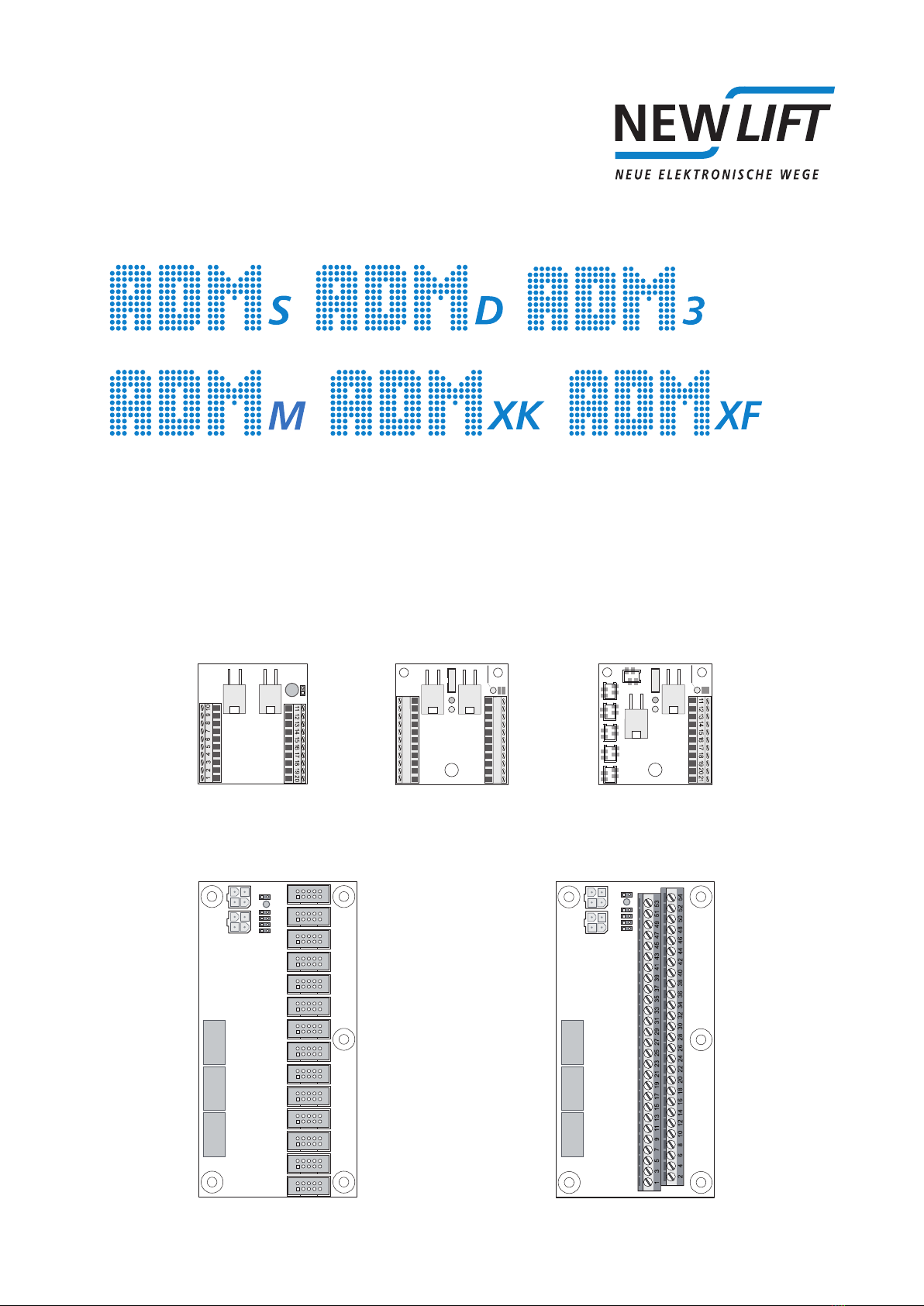
ADM-S and ADM-D land call module
Terminalassignmentandconfiguration
4 ADMmanual
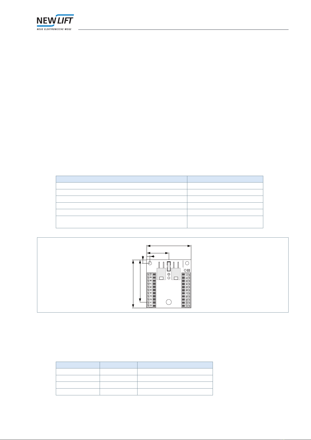
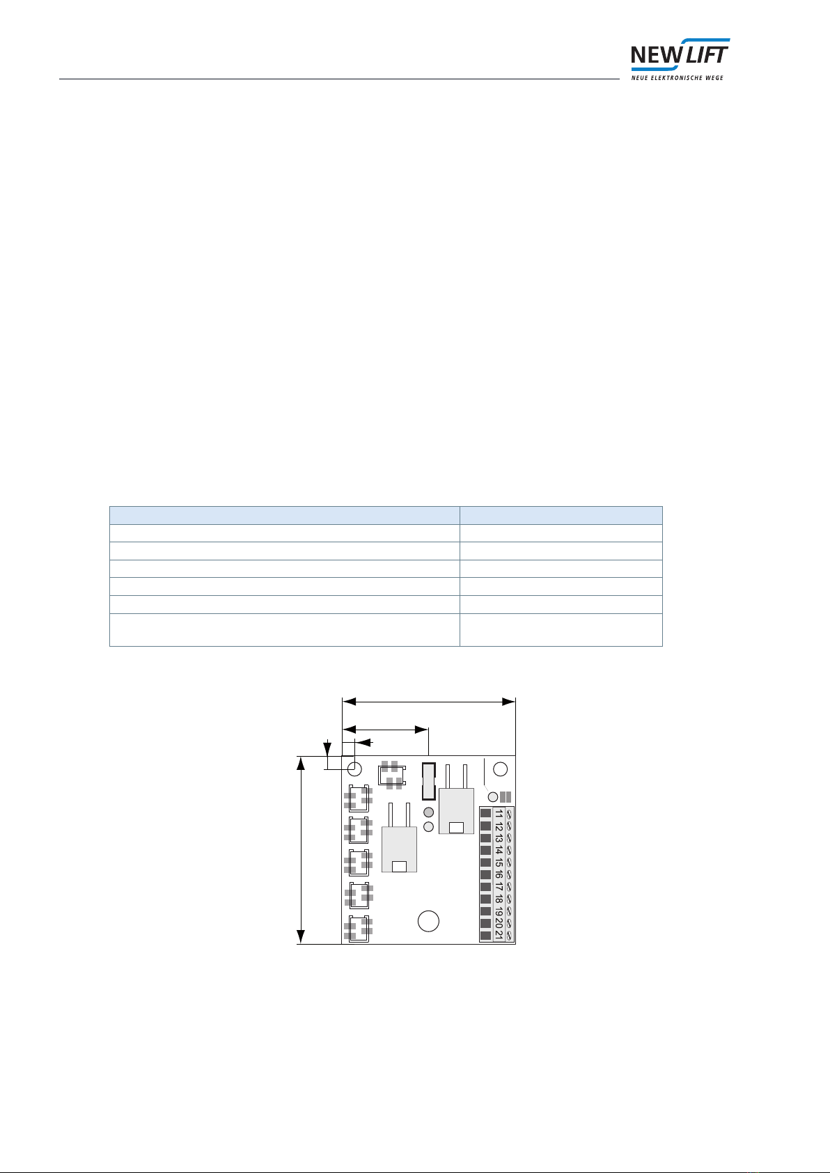
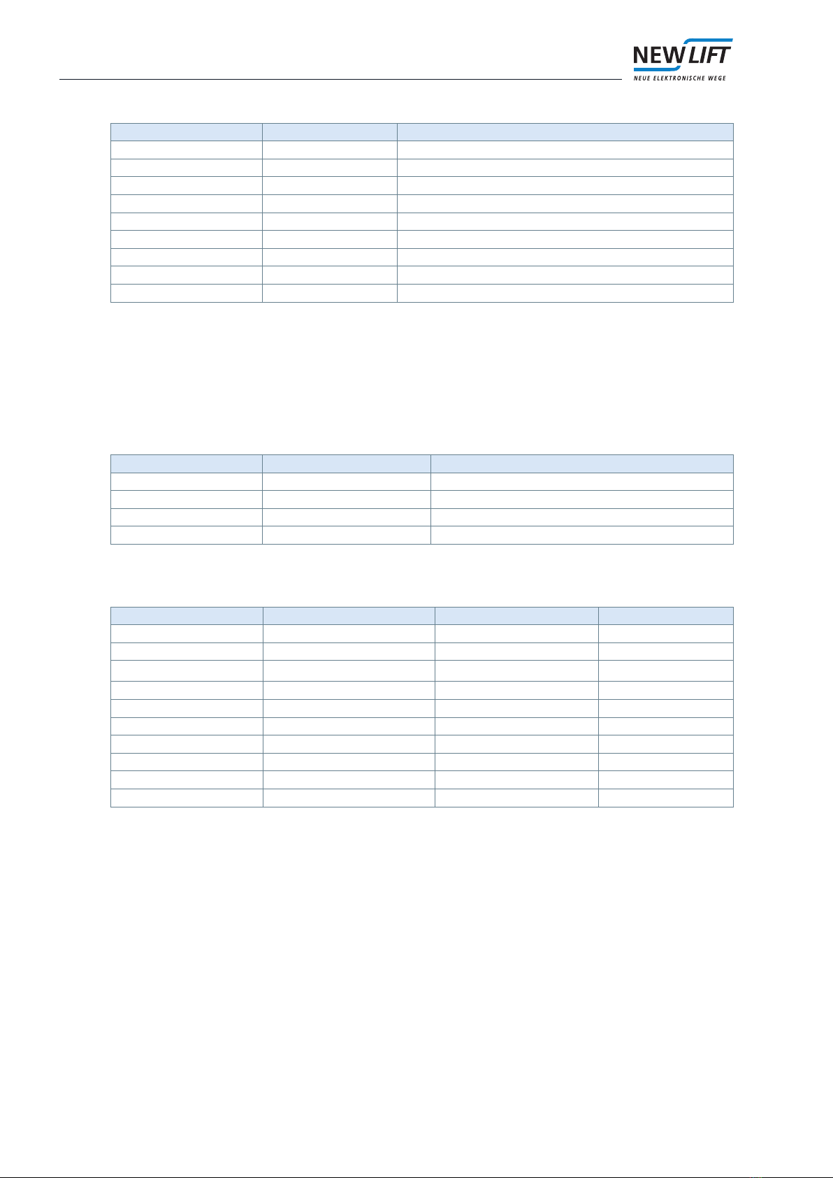
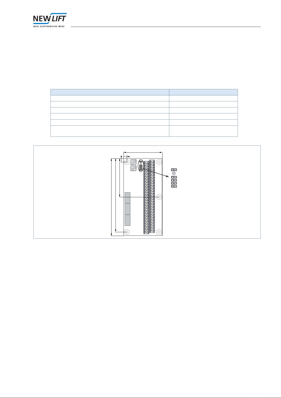
2.2.3 Terminal strip
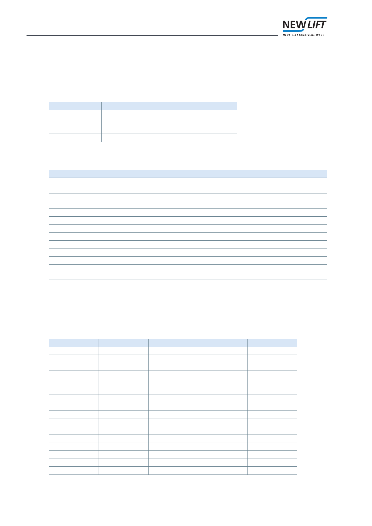
ADM-S X3
ADM-D X3
ADM-S
function / programming
ADM-D
function / programming
Technical data
1 + 24 V + 24 V P
2 Landing call UP Landing call UP I/O; L; 350 mA / 24 V
3 Landing call DOWN Landing call DOWN I/O; L; 350 mA / 24 V
4 Landing call release Landing call release O; L; 350 mA / 24 V
5 + 24 V + 24 V P
6 Out-of-order, occupied display,
special drive
Occupied display, left O; L; 350 mA / 24 V
7 Chime, oor position 5 Chime left, special drive O; L; 350 mA / 24 V
8 Direction UP Direction UP left O; L; 350 mA / 24 V
9 Direction DOWN Direction DOWN left O; L; 350 mA / 24 V
10 GND GND P
11 GND GND P
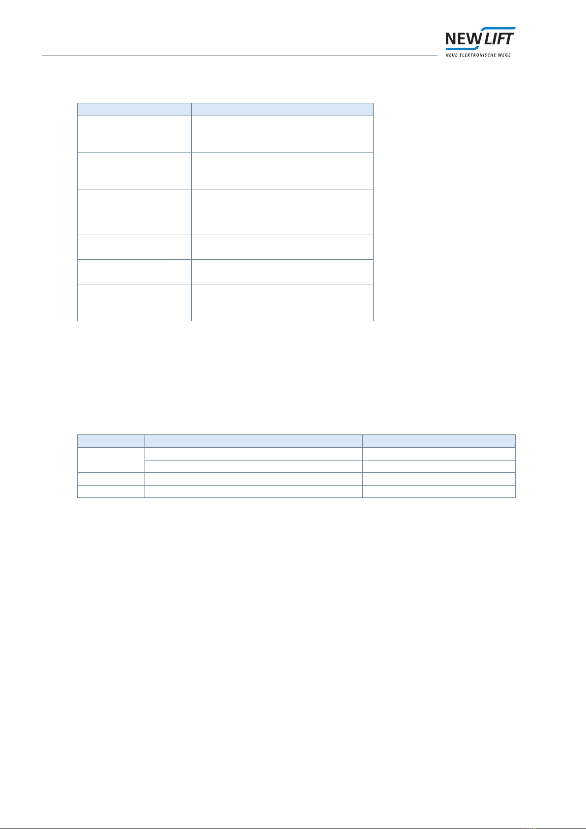
12 Key switch 1:
re recall, re recall selective, re
recall reset, landing prio, landing
prio selective, landing prio super,
remote shutdown, remote shut-
down selective, smoke alarm, soft
switch
Key switch 1:
re recall, re recall selective, re
recall reset, landing prio, landing
prio selective, landing prio super,
remote shutdown, remote shut-
down selective, smoke alarm, soft
switch
I; L
13 Key switch 2:
re recall, re recall selective, re
recall reset, landing prio, landing
prio selective, landing prio super,
remote shutdown, remote shut-
down selective, smoke alarm, soft
switch
Key switch 2:
re recall, re recall selective, re
recall reset, landing prio, landing
prio selective, landing prio super,
remote shutdown, remote shut-
down selective, smoke alarm, soft
switch
I; L
14 Floor position 4, landing prio
display, soft output 0, soft output 1,
acoustic click
Landing prio display, acoustic click O; L; 350 mA / 24 V
15 + 24 V + 24 V P
16 Floor position bit 0 Direction DOWN right O; L; 350 mA / 24 V
17 Floor position bit 1 Direction UP right O; L; 350 mA / 24 V
18 Floor position bit 3 Occupied display, right O; L; 350 mA / 24 V
19 Floor position bit 2 Chime right, special drive O; L; 350 mA / 24 V
20 GND GND P
The values in the table correspond to the factory settings. Other I/O functions can be set using the software and
can thus deviate from the table. More detailed information can be found in the FST Installation and Commissio-
ning manual. The functions congured for you can be found in your system-specic wiring diagrams.
Terminals for which several functions are listed can be set with one of them at the factory. The "Direction" func-
tion can be congured in the FST menu as a direction of travel output or a travel continuation output.
The terminals labelled with key switches 1 and 2 can be set at the factory with the functions re recall, smoke
alarm, remote shutdown and priority landing.
Other I/O functions can be set using the software.
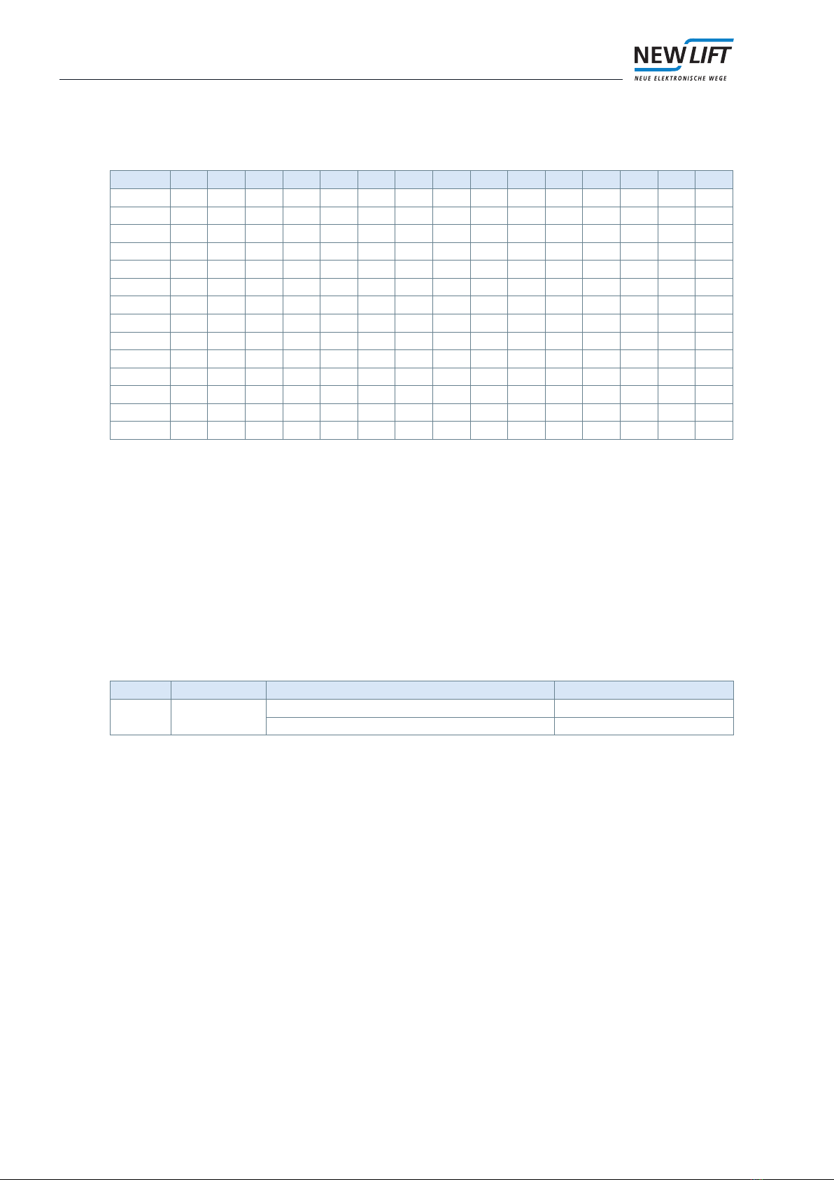
LED
LED Colour State Description
LD1 yellow briey ashes after switched on ADM ready
ashing or permanently illuminated hardware error