New lift FPM-1 User manual
MANUAL
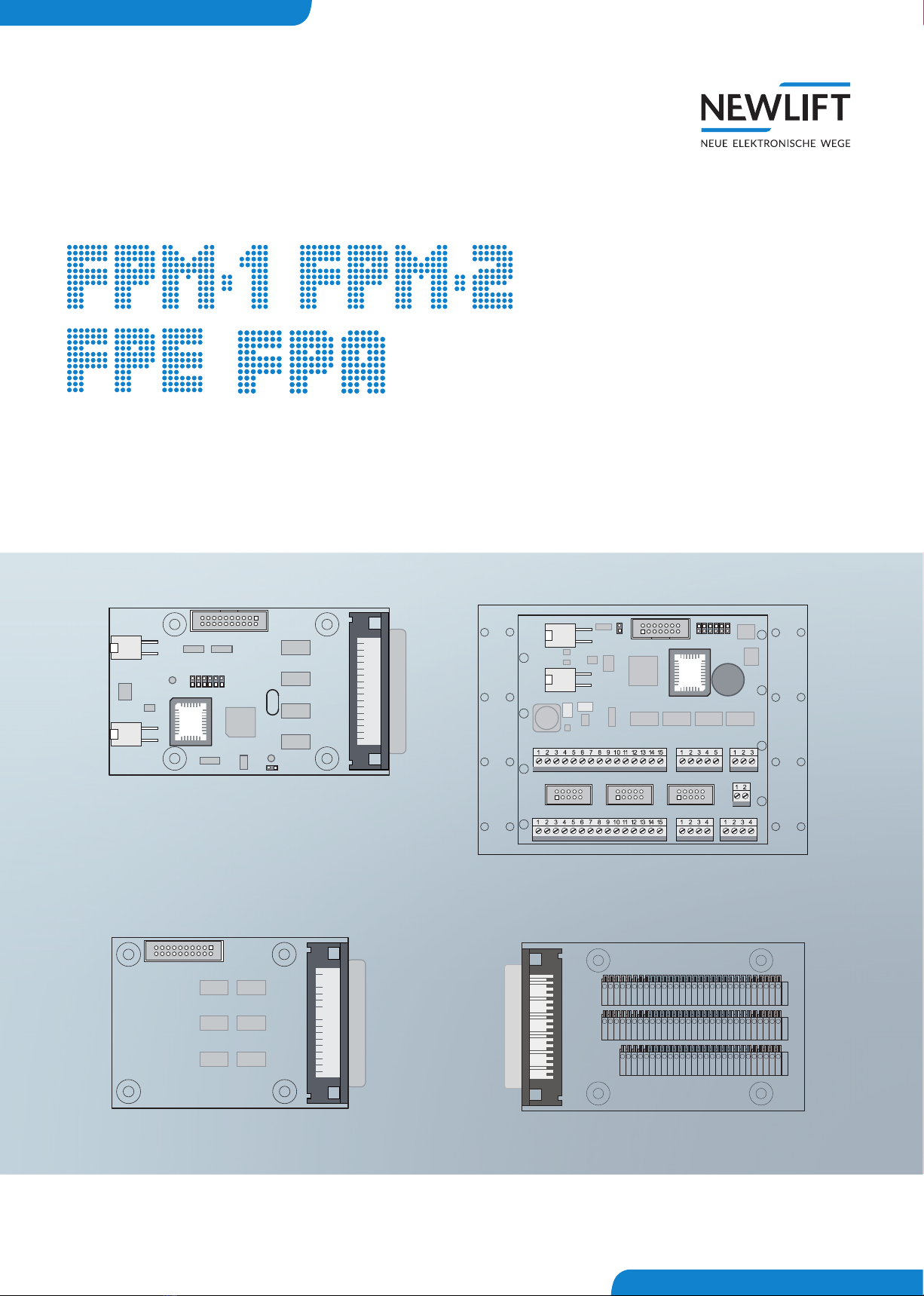
Car operating panel modules

Manual FPM-1, FPM-2, FPE, FPA
Manufacturer NEW LIFT Neue elektronische Wege
Steuerungsbau GmbH
Lochhamer Schlag 8
82166 Gräfelng
Tel +49 89 – 898 66 – 0
Fax +49 89 – 898 66 – 300
Mail [email protected]
www.newlift.de
Service line Tel +49 89 – 898 66 – 110
Mail [email protected]
Date of issue 24.11.2011
Author KH / TB
Last Change 19.11.2020 AME
Release 19.11.2020 AL
Hardware version FPM-1: V2.0 / FPM-2: V2.2 / FPE: 1.1 / FPA: 1.8
Software version FPM-1 V60 / FPM-2 V20
Doc. No. hb_FPM_2020-07_en
Copyright © NEW LIFT Steuerungsbau GmbH, 2020.
This manual is protected by copyright. All rights, including those of copying,
of reproduction, of translation and of modication, in whole or in part, are
reserved by the publisher.
No part of this description may be reproduced in any form or copied with an
electronic replication system without written permission.
Although great care has been taken in the production of texts and gures, we
cannot be held legally liable for possible mistakes and their consequences.

Manual FPM-1, FPM-2, FPE, FPA 3
Contents
1 About this manual 4
1.1 Abbreviations, characters and symbols used 4
1.2 Notation 5
1.3 Further information 5
1.4 How to contact us 5
2 Safety 6
2.1 General safety regulations 6
2.2 Applicable standards and guidelines 6
2.3 Electromagnetic compatibility (EMC) 6
2.4 Handling electronic assemblies 6
3 FPM-1 7
3.1 Technical data 7
3.2 Terminalassignmentandconguration 8
3.2.1 BusconnectionX1...X2 8
3.2.2 Jumpers 8
3.2.3 Terminals and sockets 9
3.2.4 LED‘s 11
4 FPM-2 11
4.1 Technical data 12
4.2 Terminalassignmentandconguration 13
4.2.1 Bus connection X11 ... X12 13
4.2.2 Jumpers 13
4.2.3 Terminals and terminal strips 14
4.3 Connection of an EAZ-256/64.FPM-2 17
5 FPE 18
5.1 Technicaldata 18
5.2 Terminalassignmentandconguration 18
6 FPA 20
6.1 Technical data 20
6.2 Terminalassignmentandconguration 21
About this manual
4Manual FPM-1, FPM-2, FPE, FPA
1 About this manual
This manual contains all information on the FPM-2, FPM-1, FPE and FPA car operating panel modules.
1.1 Abbreviations, characters and symbols used
Symbol /
abbreviation Meaning
FPA Car operating panel adapter; replaces the 50-pin round cable for the car
operating panel wiring
FPE Car operating panel extension; expands the car operating panel module to
include the support of the car call from oors 16 to 63
FPM Car operating panel module; controls the equipment of the car operating
panel.
Delivery condition
Settings that are supplied as standard are marked with an asterisk .
PPower
IInput
OOutput
Llow active
Hhigh active
►Operational instructions
Perform the tasks that follow this symbol in the specied order.
Warning notice
This symbol is located in front of safety-relevant information
Information notice
This symbol is located in front of relevant information.

About this manual
Manual FPM-1, FPM-2, FPE, FPA 5
1.2 Notation
Notation Meaning
Bold ›Designations of switches and actuators
›Input values
Italics ›Captions
›Cross references
›Designations of functions and signals
›Product names
Bold italics ›Remarks
LCD font ›System messages of the controller
1.3 Further information
The following documents, among others, are available for the FST control system and its components:
›ADM manual
›EAZ TFT.45.110.210 manual
›EAZ-256 manual
›EN81-20 manual
›FST-2XT/s manual
›FST-2XT MRL manual
›FST Installation & Commissioning manual
›GST-XT manual
›LCS manual
›RIO manual
›SAM manual
›UCM-A3 manual
›Update-Backup-Analysis manual
These and other up to date manuals can be found in the download area of our website at
https://www.newlift.de/downloads-311.html
1.4 How to contact us
If, after referring to this manual, you still require assistance, our service line is there for you:
Phone +49 89 – 898 66 – 110
E-mail [email protected]
Mon. - Thurs.: 8:00 a.m. – 12:00 p.m. and 1:00 p.m. – 5:00 p.m.
Fr: 8:00 a.m. – 3:00 p.m.

Safety
6Manual FPM-1, FPM-2, FPE, FPA
2 Safety
2.1 General safety regulations
The car operating panel modules must only be operated in perfect working condition in a proper
manner, safely and in compliance with the instructions, the valid accident prevention regulations and
the guidelines of the local power company.
This manual is a supplement to the FST manual and the FST Installation and Commissioning manual whose
safety guidelines must always be observed.
2.2 Applicable standards and guidelines
All car operating panel modules comply with:
›the safety guidelines for the construction and installation of passenger and goods passenger lifts (DIN
EN 81 Part 1 and 2).
›the conditions for the erection of low voltage installations with nominal voltages up to 1 kV (DIN VDE
0100).
›the contact protection measures in the machine room (VDE 0106).
›the data sheet on safety measures for the installation, maintenance and commissioning of lift systems
(ZH 1/312).
2.3 Electromagnetic compatibility (EMC)
An accredited inspection authority has inspected the FST control system and its components in
accordance with the standards, thresholds and severity levels named in EN 12015/1995 and EN
12016/1995.
The FST control system and its components are:
›immune to electrostatic discharge (EN 61000-4-2/1995)
›immune to electrostatic elds (EN 61000-4-3/1997)
›immune to fast transient disturbances (EN 61000-4-4/1995)
The electromagnetic disturbance eld strengths created by the FST control system and its components
do not exceed the permissible thresholds. (EN 55011/1997).
2.4 Handling electronic assemblies
›Keep the electronic assembly in its original packaging until installation.
›Before opening the original packaging, a static discharge must be performed. To do this, touch a
grounded piece of metal.
›During work on electronic assemblies, periodically perform this discharge procedure.
›All bus inputs and outputs not in use must be equipped with a terminal resistor (terminator).
FPM-1
Manual FPM-1, FPM-2, FPE, FPA 7
3 FPM-1
The FPM-1 car operating panel module forms the interface between the car operating panel and the
FST control system. An FPM-1 supports up to 16 car calls. The FPM-1 is connected to the FST via the
LON bus. The FPM-1 is either assembled in the car top box or in the car operating panel.
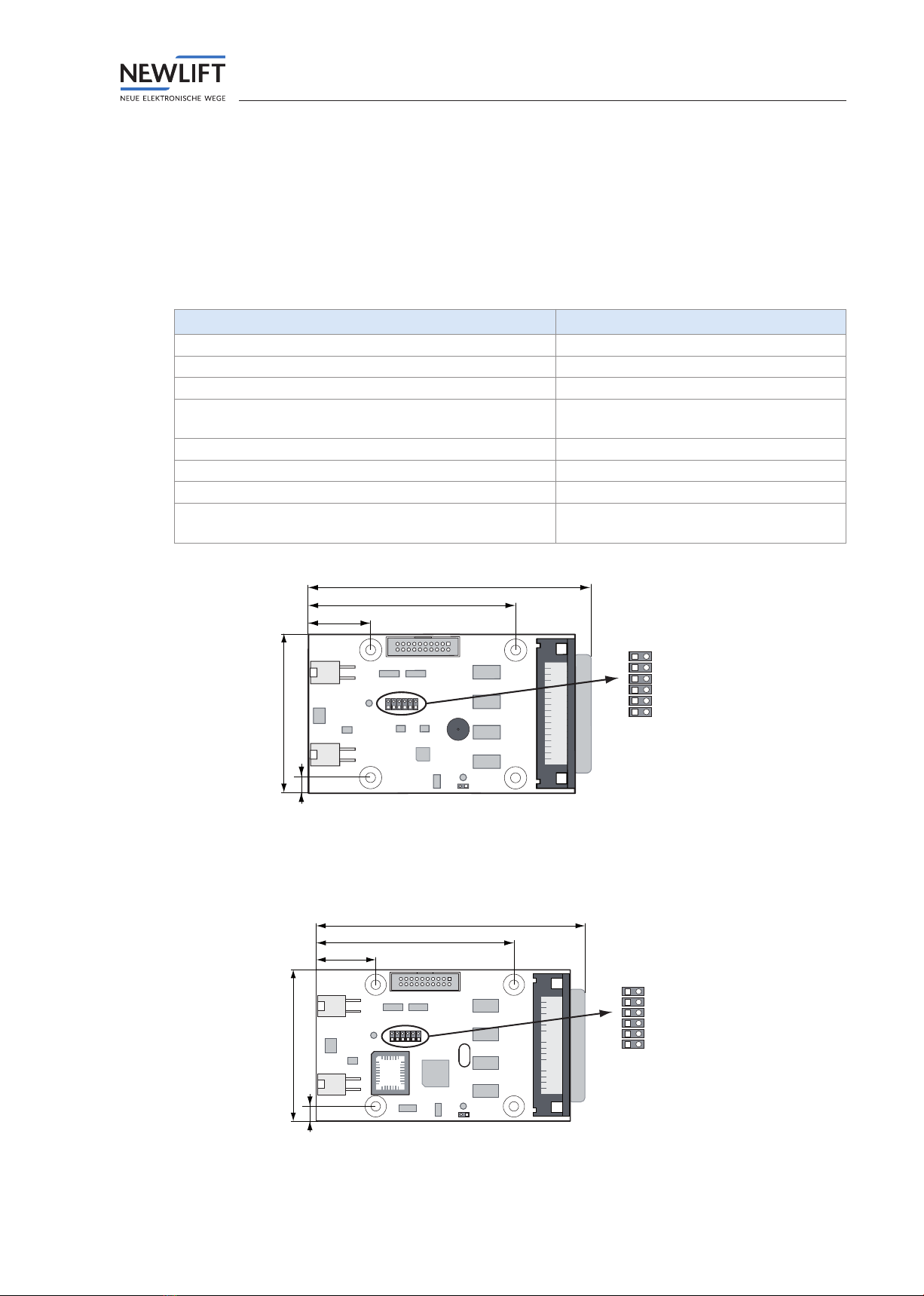
3.1 Technical data
Description Value
Supply voltage 24 V DC ±10%
Typical power consumption 60 mA
Outputs Short circuit-proof
Length x height x depth (+x: additional distance for
cable)
71 x 126 (+40) x 20 mm
Minimum mounting distance (use spacer sleeves) 8mm
Bolts M3 x 20mm
Temperature range: Storage & transport / operation -20 – +70 °C / ±0 – +60 °C
Relative humidity: Storage & transport / operation
(non-condensing)
+5 – +95 % / +15 – +85 %
X4
JT1
JT2
JK1
JK2
JK4
J2
J1
X3
X1
X2
71
126
28
93
7
FPM-1_V2 circuit board marking
The new version V2.x of the control board FPM-1 has the same function of jumper such as V1.x, a
buzzer has been added here. This can be used with the same functions as the buzzer of the FPM-2.
X4
JT1
JT2
JK1
JK2
JK4
J2
J1
X3
X1
X2
71
126
28
93
7
FPM-1 circuit board marking

FPM-1
8Manual FPM-1, FPM-2, FPE, FPA
3.2 Terminalassignmentandconguration
3.2.1 Bus connection X1 ... X2
FPM-1 X1 / X2 Colour LON bus car
Pin 1 black Bus signal A
Pin 2 white Bus signal B
Pin 3 red +24V
Pin 4 violet GND
3.2.2 Jumpers
Door side assignment
In „single door mode“, the car call of the car panel module are assigned using the jumpers on one door
side (A, B or C). If jumper J2 is plugged in, the FPM-1 is in the so-called „dual door mode,“ i.e. an FPM-1
can process car calls for door sides A and B.
If there are three car doors, a separate FPM-1 is always required for door side C.
Car door assignment Mode JT1 JT2 J2
Door A single door mode open open open
Door B single door mode plugged open open
Door C single door mode open plugged open
Door A+B dual door mode open open plugged
Door A + B
(reman input X4.4 and loading
button X4.34 act on door B.)
dual door mode open plugged plugged
Door B + A
(calls A and B switched)
dual door mode plugged open plugged
FST or car assignment
FST / car assignment Operating mode JK1 JK2 JK4
FST A single or group mode open open open
FST B group mode plugged open open
FST C group mode open plugged open
FST D group mode plugged plugged open
FST E group mode open open plugged
FST F group mode plugged open plugged
FST G group mode open plugged plugged
FST H group mode plugged plugged plugged
Car assignments of the FSM-2 car control module and the FPM-1 car panel module must be identical.
Free jumper
The service jumper J1 is not plugged in.

FPM-1
Manual FPM-1, FPM-2, FPE, FPA 9
3.2.3 Terminals and sockets
FPM-1 X3
An FPE can be connected to the FPM-1 via the X3 plug.
FPM-1: X3 Car call extension
1 + 24 V
2 + 24 V
3 + 5 V
4 + 5 V
5 Reset of SPI drivers
6 GND
7 Serial cycle
8 GND
9 Serial output
10 GND
11 Serial input
12 GND
13 SPI select 3 (car call 48..63)
14 GND
15 SPI select 2 (car call 32..47)
16 GND
17 SPI select 1 (car call 16..31)
18 GND
19 FPE detection
20 GND
FPM-1 X4
The colour code given in the following table corresponds to the 50-pin standard cable for the car
operating panel wiring. Other colour codes can be used according to the specic order.
FPM-1:
X4
Colour
code
Car operating panel
signals in "single door
mode"
Car operating panel
signals in "dual door
mode"
Technical data
1 wh "Ventilator ON" button "Ventilator ON" button I; L
2 br Door close button B Door close button B I; L
3 gn Door close button A Door close button A I; L
4ye Key switch reman
service
Key switch reman
service
I; L
5 gr Display 2 * Display 2 * I/O; L 250mA / 24V
6 pk Overload display Overload display I/O; L 250mA / 24V
7 bl Direction UP Direction UP I/O; L 250mA / 24V
8 rd + 24 V + 24 V P
9 bk Position indicator 6 Position indicator 6 I/O; L 250mA / 24V
10 pr Position indicator 3 Position indicator 3 I/O; L 250mA / 24V
11 gr pk Position indictor 0 (LSB) Position indictor 0 (LSB) I/O; L 250mA / 24V
12 rd bl Car call 15 Car call 07 door side B I/O; L 250mA / 24V
13 wh gn Car call 12 Car call 04 door side B I/O; L 250mA / 24V
14 br gn Car call 09 Car call 01 door side B I/O; L 250mA / 24V

FPM-1
10 Manual FPM-1, FPM-2, FPE, FPA
FPM-1:
X4
Colour
code
Car operating panel
signals in "single door
mode"
Car operating panel
signals in "dual door
mode"
Technical data
15 wh ye Car call 06 Car call 06 door side A I/O; L 250mA / 24V
16 ye br Car call 03 Car call 03 door side A I/O; L 250mA / 24V
17 wh gr Car call 00 Car call 00 door side A I/O; L 250mA / 24V
18 gr br GND GND P
19 wh pk GND GND P
20 pk br GND GND P
21 wh bl GND GND P
22 br bl + 24 V + 24 V P
23 wh rd + 24 V + 24 V P
24 br rd + 24 V + 24 V P
25 wh bk Position indicator 7
(MSB)
Position indicator 7
(MSB)
I/O; L 250mA / 24V
26 br bk Position indicator 4 Position indicator 4 I/O; L 250mA / 24V
27 gr gn Position indicator 1 Position indicator 1 I/O; L 250mA / 24V
28 ye gr Car call release Car call release O; L 250mA / 24V
29 pk gn Car call 13 Car call 05 door side B I/O; L 250mA / 24V
30 ye pk Car call 10 Car call 02 door side B I/O; L 250mA / 24V
31 gn bl Car call 07 Car call 07 door side A I/O; L 250mA / 24V
32 ye bl Car call 04 Car call 04 door side A I/O; L 250mA / 24V
33 gn rd Car call 01 Car call 01 door side A I/O; L 250mA / 24V
34 ye rd Landing control OFF or "loading control" button (see
FST manual)
I; L
35 gn bk Door open button B or partition door button (see
FST manual)
I; L
36 ye bk Door open button A Door open button A I; L
37 gr bl Key switch car priority Key switch car priority I; L
38 pk bl Display 1 * Display 1 * I/O; L 250mA / 24V
39 gr rd Display 0 * Display 0 * I/O; L 250mA / 24V
40 pk rd Direction DOWN Direction DOWN I/O; L 250mA / 24V
41 gr bk GND GND P
42 pk bk Position indicator 5 Position indicator 5 I/O; L 250mA / 24V
43 bl bk Position indicator 2 Position indicator 2 I/O; L 250mA / 24V
44 rd bk Secondary car call release (e.g. active with card
readers in car)
I/O; L 250mA / 24V
45 wh br bk Car call 14 Car call 06 door side B I/O; L 250mA / 24V
46 ye gn bk Car call 11 Car call 03 door side B I/O; L 250mA / 24V
47 pk gr bk Car call 08 Car call 00 door side B I/O; L 250mA / 24V
48 bk bl rd Car call 05 Car call 05 door side A I/O; L 250mA / 24V
49 wh gn bk Car call 02 Car call 02 door side A I/O; L 250mA / 24V
50 gn br bk + 24 V + 24 V P
* see FST2XT-XTs manual „5.5.5 Display 0 ... 2“

FPM-1
Manual FPM-1, FPM-2, FPE, FPA 11
3.2.4 LED‘s
LED Colour State Description
LD1 yellow ashes briey FPM-1 ready
ashing or permanently
illuminated
hardware error
LD2 green On supply voltage (+5 V) is present
4 FPM-2
The FPM-2 is an I/O component of the FST which controls the input and output signals in the car. In
addition, it implements the emergency light according to EN81-1/2 as well as the acoustic button
acknowledgement according to EN81-70.
The car operating panel module is looped in the bus via the two bus connectors X11 and X12 and is also
connected to the data bus with 24V.
The following inputs/outputs are supported by the module:
• 24V inputs for reman service, car priority and loading mode (recongurable)
• 24V/0.2A I/Os for 16 car calls with two releases (primary and secondary)
• 3 outputs with 24V/0.2A (4W); re indicators, overload and reserve
• 2 outputs for direction indicators, each with 24V/0.2A (max. 4 Watt)
• Four inputs for two doors (A/B), each with a door open and a door close button
All inputs and outputs are low active! All outputs are protected against short circuit!
The EAZ-256.64.FPM-2 position indicator can be connected to the X-5 14-pin pin header (NEW
internal SPI connection) (see chapter „4.3 Connection of an EAZ-256/64.FPM-2“ on page 17), since it
does not have any of its own LON nodes. The installation position of this position indicator is dened
with the V jumper.
The FPM-2 has no outputs for oor position outputs so that only active LON modules can be used as
position indicators in addition to the aforementioned EAZ-256.64.FPM-2 position indicator.
The acoustic button acknowledgement according to EN81-70 is already integrated on the FPM-2
module and does not need to be led to the terminals. It can be switched on or off via the FST menu (as
of software version FST V1.100-0374). The Piezo buzzer, which realises the button acknowledgement,
is used simultaneously to signal different special conditions (overload, chemical carrier, ...).
Both the primary and secondary releases are also separately led to the X6 terminal in order to connect
card readers or key switches for implementing access controls.
The FPM-2 is delivered assembled in a type MA9999 luminous panel from SCHÄFER. The company
logo, information about load capacity, maximum number of persons, year of manufacture, serial
number and information for the case of re can be inserted as a printed slide between the transparent
front and the white diffuse cover of the luminous panel.
For emergency lighting: Four white LED‘s on the back of the FPM-2 module illuminate the text eld as
soon as the car lighting fails.
FPM-1
12 Manual FPM-1, FPM-2, FPE, FPA
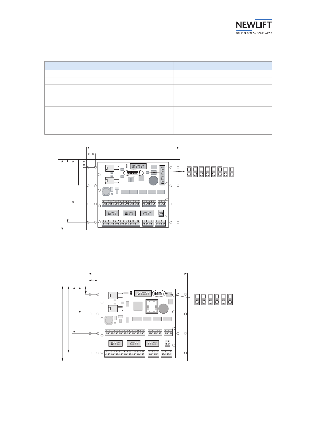
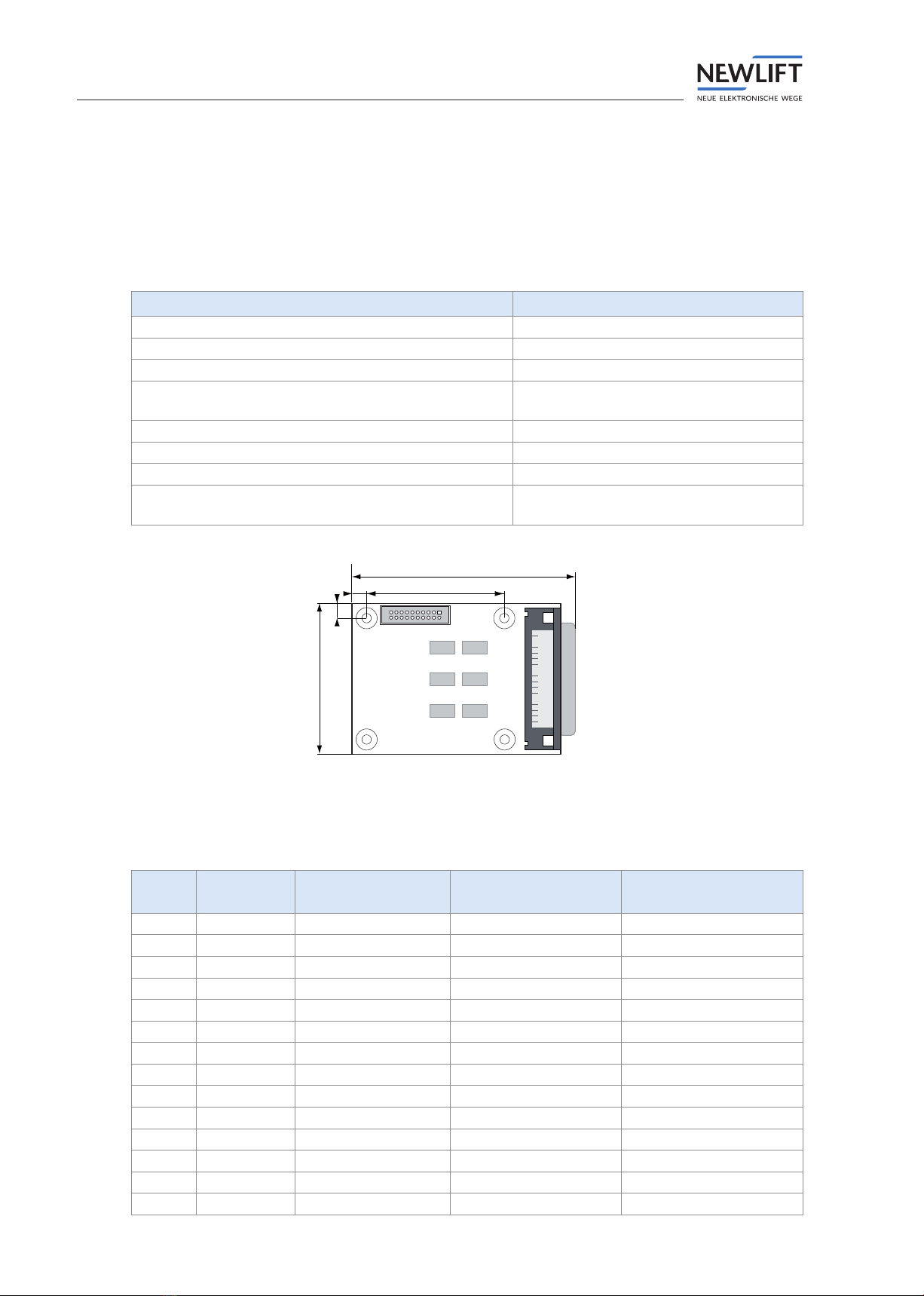
4.1 Technical data
Description Value
Supply voltage 24 V DC ±10%
Typical power consumption 60 mA
Outputs Short circuit-proof
Length x height x depth 143 x 108 x 44 mm
Bolts M3 x 12mm
Preview window aperture 99.1x99.1 mm; r = 2.8mm
Temperature range: Storage & transport / operation -20 – +70 °C / ±0 – +60 °C
Relative humidity: Storage & transport / operation
(non-condensing)
+5 – +95 % / +15 – +85 %
X11 J1
JV JK2 JT1
JK1 JK3 JT2
X12
X5
X2
X1
X21 X22 X23
X8 X7
X6
X3 X4
143
13,5
12
40
68
96
108
X9
J8
J9
FPM-2_V2 circuit board marking
X11 J1
JV JT1 JK2
JT2 JK4 JK1
X12
X5
X2
X1
X21 X22 X23
X8 X7
X6
X3 X4
143
13,5
12
40
68
96
108
FPM-2 circuit board marking

FPM-1
Manual FPM-1, FPM-2, FPE, FPA 13
4.2 Terminalassignmentandconguration
4.2.1 Bus connection X11 ... X12
FPM-2 X11 /
X12
Cable colour Designation
1 black RS-485 LON Bus A
2 white RS-485 LON Bus B
3 red +24V
4 violet GND or 0V
4.2.2 Jumpers
FST or car assignment
FST / car assignment Operating mode JK1 JK2 JK3
FST A single or group mode open open open
FST B group mode plugged open open
FST C group mode open plugged open
FST D group mode plugged plugged open
FST E group mode open open plugged
FST F group mode plugged open plugged
FST G group mode open plugged plugged
FST H group mode plugged plugged plugged
Door side assignment
Car door assignment Door mode JT1 JT2
Door A single door mode open open
Door B single door mode plugged open
Door C single door mode open plugged
Door A+B dual door mode plugged plugged
Installation position of the EAZ-256.64
Installation position EAZ-256.64 JV
Vertical installation position plugged
Horizontal installation position open
The jumpers J8 and J9 are not in use yet.

FPM-1
14 Manual FPM-1, FPM-2, FPE, FPA
4.2.3 Terminals and terminal strips
Depending on whether you would like to operate the car in single or dual door mode, the functions of
the individual pins of the X1 and X2 terminals as well as associated terminal strips X21, X22 and X23
change. The following table contains an overview of the respective functions:
FPM-2
X1
Function single door
mode
Function dual door
mode
Connected to Technical data
1 +24V +24V FPM-2 X21.10 P
2 Car call 00 Car call 00 A FPM-2 X21.1 I/O; L; 250mA / 24V
3 Car call 01 Car call 01 A FPM-2 X21.2 I/O; L; 250mA / 24V
4 Car call 02 Car call 02 A FPM-2 X21.3 I/O; L; 250mA / 24V
5 Car call 03 Car call 03 A FPM-2 X21.4 I/O; L; 250mA / 24V
6 Car call 04 Car call 04 A FPM-2 X21.5 I/O; L; 250mA / 24V
7 Car call 05 Car call 05 A FPM-2 X21.6 I/O; L; 250mA / 24V
8 Car call 06 Car call 06 A FPM-2 X21.7 I/O; L; 250mA / 24V
9 Car call 07 Car call 07 A FPM-2 X21.8 I/O; L; 250mA / 24V
10 Car call release 01 Car call release 01 FPM-2 X21.9 O; L; 250mA / 24V
11 Door open button Door open button A FPM-2 X23.1 I/O; L; 250mA / 24V
12 Door close button Door close button A FPM-2 X23.2 I/O; L; 250mA / 24V
13 Key switch car priority Key switch car
priority
FPM-2 X23.7 I; L; 250mA / 24V
14 "Ventilator ON"
button
"Ventilator ON"
button
FPM-2 X23.5 I; L; 250mA / 24V
15 GND GND FPM-2 X23.9 P
FPM-2
X2
Function single door
mode
Function dual door
mode
Connected to Technical data
1 +24V +24V FPM-2 X22.10 P
2 Car call 08 Car call 00 B FPM-2 X22.1 I/O; L; 250mA / 24V
3 Car call 09 Car call 01 B FPM-2 X22.2 I/O; L; 250mA / 24V
4 Car call 10 Car call 02 B FPM-2 X22.3 I/O; L; 250mA / 24V
5 Car call 11 Car call 03 B FPM-2 X22.4 I/O; L; 250mA / 24V
6 Car call 12 Car call 04 B FPM-2 X22.5 I/O; L; 250mA / 24V
7 Car call 13 Car call 05 B FPM-2 X22.6 I/O; L; 250mA / 24V
8 Car call 14 Car call 06 B FPM-2 X22.7 I/O; L; 250mA / 24V
9 Car call 15 Car call 07 B FPM-2 X22.8 I/O; L; 250mA / 24V
10 Car call release 02 Car call release 02 FPM-2 X22.9 O; L; 250mA / 24V
11 Door open button Door open button B FPM-2 X23.3 I; L; 250mA / 24V
12 Door close button Door close button B FPM-2 X23.4 I; L; 250mA / 24V
13 Key switch fireman
service
Key switch fireman
service
FPM-2 X23.6 I; L; 250mA / 24V
14 Pin 34 function Pin 34 function FPM-2 X23.8 I; L; 250mA / 24V
15 GND GND FPM-2 X23.9 P
FPM-1
Manual FPM-1, FPM-2, FPE, FPA 15
FPM-2 X3 Designation Technical data
1 +24V P
2 Display 1 * O; L; 250mA / 24V
3 Display 2 * O; L; 250mA / 24V
4 Display 0 * O; L; 250mA / 24V
5 GND P
* see FST2XT-XTs manual „5.5.5 Display 0 ... 2“
FPM-2 X4 Designation Technical data
1 Direction UP O; L; 250mA / 24V
2 Direction DOWN O; L; 250mA / 24V
3 +24V P
FPM-2 X6 Designation Technical data
1 Car call release 01 O
2 Car call release 02 O
FPM-2 X7
FPM-2X8
Designation Technical data
1 Emergency light P
2 GND P
3 Emergency call (COM)
4 Emergency call (NC)
The EAZ-256.64 can be connected to the FPM-2 X5. This EAZ does not then require its own LON
nodes.
The LON bus is connected to X11 and X12 with the usual 4-pin bus connector.
The following pin headers X21, X22 and X23 serve for the connection of the so-called HUNIOLIFT
buttons by means of a 10-pin ribbon cable.
FPM-2
X21
Designation Technical data
X21.1 Car call 00 I/O; L; 250mA / 24V
X21.2 Car call 01 I/O; L; 250mA / 24V
X21.3 Car call 02 I/O; L; 250mA / 24V
X21.4 Car call 03 I/O; L; 250mA / 24V
X21.5 Car call 04 I/O; L; 250mA / 24V
X21.6 Car call 05 I/O; L; 250mA / 24V
X21.7 Car call 06 I/O; L; 250mA / 24V
X21.8 Car call 07 I/O; L; 250mA / 24V
X21.9 Car call release 01 O; L; 250mA / 24V
X21.10 +24V P
FPM-1
16 Manual FPM-1, FPM-2, FPE, FPA
FPM-2
X22
Designation Technical data
X22.1 Car call 08 I/O; L; 250mA / 24V
X22.2 Car call 09 I/O; L; 250mA / 24V
X22.3 Car call 10 I/O; L; 250mA / 24V
X22.4 Car call 11 I/O; L; 250mA / 24V
X22.5 Car call 12 I/O; L; 250mA / 24V
X22.6 Car call 13 I/O; L; 250mA / 24V
X22.7 Car call 14 I/O; L; 250mA / 24V
X22.8 Car call 15 I/O; L; 250mA / 24V
X22.9 Car call release 01 O; L; 250mA / 24V
X22.10 +24V P
FPM-2
X23
Designation Technical data
X23.1 Door open button
A
I; L; 250mA / 24V
X23.2 Door close button
A
I; L; 250mA / 24V
X23.3 Door open button
B
I; L; 250mA / 24V
X23.4 Door close button
B
I; L; 250mA / 24V
X23.5 Fan I; L; 250mA / 24V
X23.6 Fire recall I; L; 250mA / 24V
X23.7 Priority I; L; 250mA / 24V
X23.8 Loading I; L; 250mA / 24V
X23.9 GND P
X23.10 +24V P
The acoustic acknowledgement is already integrated on the FPM-2 assembly and does not need to be
led to the terminals.
Emergency light function: As soon as the supply voltage of the car lighting fails, four white LEDs
illuminate the text eld.
FPM-1
Manual FPM-1, FPM-2, FPE, FPA 17
4.3 Connection of an EAZ-256/64.FPM-2
With the EAZ-256/64.FPM-2, NEW LIFT offers a low-cost variant of the EAZ-256/64 position
indicator. The position indicator and the car operating panel module form an optically uniform system.
For the functional text, the EAZ-256.64.FPM-2 must be connected to the FPM-2 via the X5 pin header
using the 14-wire ribbon cable.
The maximum length of ribbon cable conntected to X5 must not exceed 0,25m.
From 0,25m to 1,5m the use of the CLF-module (art. no.: 37-02150) is additionally required. It is not
possible to use the cable longer than 1,5m, use alternatively a LON EAZ.
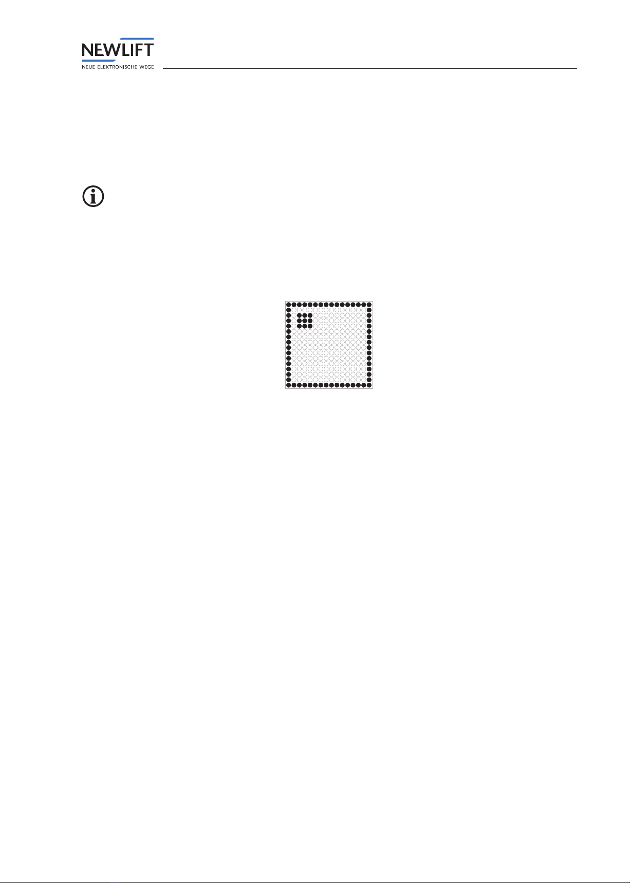
If the following pattern is displayed on the screen after the FPM-2 supply voltage has been switched on
via bus connector X11 or X12, there is no bus connection.
Display for checking the function
FPE
18 Manual FPM-1, FPM-2, FPE, FPA
5 FPE
The FPE is the extension of the FPM-1. The module is connected to the FPM-1 car operating panel
module via FPE X3. This means the car calls for oors 16 to 63 are supported.
5.1 Technical data
Description Value
Supply voltage 24 V DC ±10%
Typical power consumption 10 mA
Outputs Short circuit-proof
Length x height x depth (+x: additional distance for
cable)
104 x 70 x 33 mm
Min. installation distance (use spacer sleeves) 8mm
Bolts M3 x 18mm
Temperature range: Storage & transport / operation -20 – +70 °C / ±0 – +60 °C
Relative humidity: Storage & transport / operation
(non-condensing)
+5 – +95 % / +15 – +85 %
X2
X3
104
70
7
7 65
FPE circuit board marking
5.2 Terminalassignmentandconguration
FPE
X2
Colour code Signals in single
door mode
Signals in dual door
mode
Technical data
1 wh +24V +24V P
2 br Car call 61 Car call 29 door side B I/O; L; 250mA / 24V
3 gn Car call 58 Car call 26 door side B I/O; L; 250mA / 24V
4 ye Car call 55 Car call 31 door side A I/O; L; 250mA / 24V
5 gr Car call 52 Car call 28 door side A I/O; L; 250mA / 24V
6 pk Car call 49 Car call 25 door side A I/O; L; 250mA / 24V
7 bl Car call 46 Car call 22 door side B I/O; L; 250mA / 24V
8 rd Car call 43 Car call 19 door side B I/O; L; 250mA / 24V
9 bk Car call 40 Car call 16 door side B I/O; L; 250mA / 24V
10 pr Car call 37 Car call 21 door side A I/O; L; 250mA / 24V
11 gr pk Car call 34 Car call 18 door side A I/O; L; 250mA / 24V
12 rd bl Car call 31 Car call 15 door side B I/O; L; 250mA / 24V
13 wh gn Car call 28 Car call 12 door side B I/O; L; 250mA / 24V
14 br gn Car call 25 Car call 09 door side B I/O; L; 250mA / 24V

FPE
Manual FPM-1, FPM-2, FPE, FPA 19
FPE
X2
Colour code Signals in single
door mode
Signals in dual door
mode
Technical data
15 wh ye Car call 22 Car call 14 door side A I/O; L; 250mA / 24V
16 ye br Car call 19 Car call 11 door side A I/O; L; 250mA / 24V
17 wh gr Car call 16 Car call 08 door side A I/O; L; 250mA / 24V
18 gr br Car call 62 Car call 30 door side B I/O; L; 250mA / 24V
19 wh pk Car call 59 Car call 27 door side B I/O; L; 250mA / 24V
20 pk br Car call 56 Car call 24 door side B I/O; L; 250mA / 24V
21 wh bl Car call 53 Car call 29 door side A I/O; L; 250mA / 24V
22 br bl Car call 50 Car call 26 door side A I/O; L; 250mA / 24V
23 wh rd Car call 47 Car call 23 door side B I/O; L; 250mA / 24V
24 br rd Car call 44 Car call 20 door side B I/O; L; 250mA / 24V
25 wh bk Car call 41 Car call 17 door side B I/O; L; 250mA / 24V
26 br bk Car call 38 Car call 22 door side A I/O; L; 250mA / 24V
27 gr gn Car call 35 Car call 19 door side A I/O; L; 250mA / 24V
28 ye gr Car call 32 Car call 16 door side A I/O; L; 250mA / 24V
29 pk gn Car call 29 Car call 13 door side B I/O; L; 250mA / 24V
30 ye pk Car call 26 Car call 10 door side B I/O; L; 250mA / 24V
31 gn bl Car call 23 Car call 15 door side A I/O; L; 250mA / 24V
32 ye bl Car call 20 Car call 12 door side A I/O; L; 250mA / 24V
33 gn rd Car call 17 Car call 09 door side A I/O; L; 250mA / 24V
34 ye rd Car call 63 Car call 31 door side B I/O; L; 250mA / 24V
35 gn bk Car call 60 Car call 28 door side B I/O; L; 250mA / 24V
36 ye bk Car call 57 Car call 25 door side B I/O; L; 250mA / 24V
37 gr bl Car call 54 Car call 30 door side A I/O; L; 250mA / 24V
38 pk bl Car call 51 Car call 27 door side A I/O; L; 250mA / 24V
39 gr rd Car call 48 Car call 24 door side A I/O; L; 250mA / 24V
40 pk rd Car call 45 Car call 21 door side B I/O; L; 250mA / 24V
41 gr bk Car call 42 Car call 18 door side B I/O; L; 250mA / 24V
42 pk bk Car call 39 Car call 23 door side A I/O; L; 250mA / 24V
43 bl bk Car call 36 Car call 20 door side A I/O; L; 250mA / 24V
44 rd bk Car call 33 Car call 17 door side A I/O; L; 250mA / 24V
45 wh br bk Car call 30 Car call 14 door side B I/O; L; 250mA / 24V
46 ye gn bk Car call 27 Car call 11 door side B I/O; L; 250mA / 24V
47 pk gr bk Car call 24 Car call 08 door side B I/O; L; 250mA / 24V
48 bk bl rd Car call 21 Car call 13 door side A I/O; L; 250mA / 24V
49 wh gn bk Car call 18 Car call 10 door side A I/O; L; 250mA / 24V
50 gn br bk +24V +24V P
FPE
20 Manual FPM-1, FPM-2, FPE, FPA
FPE:
X3
Car call extension
1 + 24 V
2 + 24 V
3 + 5 V
4 + 5 V
5 Reset of SPI drivers
6 GND
7 Serial cycle
8 GND
9 Serial output
10 GND
11 Serial input
12 GND
13 SPI select 3 (car call 48..63)
14 GND
15 SPI select 2 (car call 32..47)
16 GND
17 SPI select 1 (car call 16..31)
18 GND
19 FPE detection
20 GND
6 FPA
The FPA car operating panel adapter provides tension spring terminals for all car operating panel
signals of the FPM-1 X4 plug. It replaces the 50-pin round cable for the car operating panel wiring.
The FPA is connected to the X4 plug of the FPM-1 car operating panel module via the 50-pin X4 plug.
Switching from „single door mode“ to „dual door mode“ is done on the associated FPM-1 with the JK2
jumper. (see chapter „3.2.2 Jumpers“ on page 8)
6.1 Technical data
Description Value
Supply voltage 24 V DC ±10%
Typical power consumption 60 mA
Outputs Short circuit-proof
Length x height x depth (+x: additional distance for
cable)
70 x 125 x 20 (+10) mm
Min. installation distance (use spacer sleeves) 8mm
Bolts M3 x 20mm
Temperature range: Storage & transport / operation -20 – +70 °C / ±0 – +60 °C
Relative humidity: Storage & transport / operation
(non-condensing)
+5 – +95 % / +15 – +85 %
This manual suits for next models
3
Table of contents
Other New lift Industrial Equipment manuals


Popular Industrial Equipment manuals by other brands

KTR-Group
KTR-Group KTR-STOP M-A-F B Series Operating & assembly instructions

Cyklos
Cyklos GPM 450 verSA operating instructions

Greenheck
Greenheck ESD-202 Installation, operation and maintenance manual

Lukas
Lukas HP 25/ T700R operating instructions

Siemens
Siemens SCALANCE Advanced Settings

ABB
ABB HT609436 operating manual


