New lift EAZ DMT-TFT.110 User manual

Destination call terminal
MANUAL
DMT - TFT.110

Manual DMT-TFT.110
Manufacturer NEW LIFT Steuerungsbau GmbH
Lochhamer Schlag 8
82166 Gräfelng
Tel +49 89 – 898 66 – 0
Fax +49 89 – 898 66 – 300
Mail [email protected]
www.newlift.de
Service line Tel +49 89 – 898 66 – 110
Mail [email protected]
Date of issue 04.09.2017
Author ASC / DOS
Last Change 16.11.2020 AME
Release 16.11.2020 AL
Hardware version DMT-TFT.110
Software version V1.110-0105 / DMT2403
Doc. No. hb_DMT-TFT.110_2020-09_en
Copyright © NEW LIFT Steuerungsbau GmbH, 2020.
This manual is protected by copyright. All rights, including those of copying,
of reproduction, of translation and of modication, in whole or in part, are
reserved by the publisher.
No part of this description may be reproduced in any form or copied with an
electronic replication system without written permission.
Although great care has been taken in the production of texts and gures, we
cannot be held legally liable for possible mistakes and their consequences.

Manual DMT-TFT.110 3
Contents
1 General 5
1.1 Abbreviations, characters and symbols used 5
1.2 Notation 5
1.3 Further information 6
1.4 How to contact us 6
2 Safety 7
2.1 General safety regulations 7
2.2 Handling electronic assemblies 7
3 Technical data 8
3.1 General 8
3.2 Functional 8
3.3 Pin assignment 9
3.4 Wiring 11
3.4.1 Standard wiring 11
3.4.2 Wiring for individual buttons 11
3.4.3 Wiring for 2 x 6 matrix 12
3.4.4 Wiring for 4 x 4 matrix 13
4 Installation and commissioning 14
4.1 Unpacking 14
4.2 Installation 14
4.2.1 Installation dimensions 15
4.2.2 Adapting installation position 17
5 Software 18
5.1 Destination call entry system 18
5.2 Card reader system 20
5.3 Code entry system 21
5.4 Special functions 22
5.5 Destino SAM 24
5.6 Designs 24
5.6.1 Standard design 24
5.6.2 Installation-specicdesign 25
6 Congurationmenu 26
6.1 Starting menu 26
6.2 Menu structure 27
6.3 Start screen and main menu 28
6.3.1 Start screen 28
6.4 Navigation and operation 29
6.4.1 Navigation 29
6.4.2 USB port 29
6.4.3 Selecting menu item 30
6.4.4 Saving and rejecting settings 30

4Manual DMT-TFT.110
6.4.5 Conrmingandcancellingaction 30
6.4.6 Exiting main menu 31
6.5 Submenus 32
6.5.1 Overview of submenus 32
6.5.2 Basic settings 33
6.5.3 Time settings 36
6.5.4 Access control (card reader settings) 37
6.5.5 Password settings for code entry 39
6.5.6 Volume control 40
6.5.7 USB services 41
7 Software update 44
7.1 Updatingrmware 44
7.2 Updating Neuron 45

General
Manual DMT-TFT.110 5
1 General
The DMT-TFT.110 is a further product, in addition to the touch terminal, for entering destination calls
in our destination call system Destino. In this system, the destination calls are made using mechanical
buttons. Apart from the standard calls, the DMT-TFT.110 provides other functions (e.g. lift modes for
disabled persons or service operations) which can be initiated by button, card reader or code entry. On
the one hand, the conguration of the terminal is based on the conguration of the installation; on the
other hand, the design can be congured freely within the framework of the possibilities offered.
1.1 Abbreviations, characters and symbols used
Symbol /
abbreviation Meaning
DMT Destino mechanical terminal
FST Field bus controller
GST Group controller
ADM Landing call module
SAM Speech output module
FPM Car operating panel module
Menü Menu integrated in the TFT for editing display settings
►Operational instructions
Perform the tasks that follow this symbol in the specied order.
Warning notice
This symbol is located in front of safety-relevant information
Information notice
This symbol is located in front of relevant information.
1.2 Notation
Notation Meaning
Bold ›Designations of switches and actuators
›Input values
Italics ›Captions
›Cross references
›Designations of functions and signals
›Product names
Bold italics ›Remarks
LCD font ›System messages of the controller

General
6Manual DMT-TFT.110
1.3 Further information
The following documents, among others, are available for the FST controller and its components.
›ADM manual
›EAZ TFT.45.110.210 manual
›EAZ-256 manual
›EN81-20 manual
›FPM manual
›FST-2XT/s manual
›FST-2XT MRL manual
›FST installation and commissioning manual
›GST-XT manual
›LCS manual
›RIO manual
›SAM manual
›UCM-A3 manual
›Update backup analysis manual
These and other current manuals can be found in the download area of our website at
https://www.newlift.de/downloads.html
1.4 How to contact us
If, after referring to this manual, you still require assistance, our service line is there for you:
Phone +49 89 – 898 66 – 110
E-mail [email protected]
Mon. - Thurs.: 8:00 a.m. – 12:00 p.m. and 1:00 p.m. – 5:00 p.m.
Fr: 8:00 a.m. – 3:00 p.m.

Safety
Manual DMT-TFT.110 7
2 Safety
2.1 General safety regulations
The position indicator may only be operated in perfect working condition in a proper manner, safely
and in compliance with the manual, the valid accident prevention regulations and the guidelines of the
local power company.
This manual is a supplement to the FST manual and the FST Installation and Commissioning manual whose
safety guidelines must always be observed.
2.2 Handling electronic assemblies
Electrostatic charging
►Keep the electronic assembly in its original packaging until installation to prevent damage.
►Before opening the original packaging, a static discharge must be performed!
To do this, touch a grounded piece of metal.
►During work on electronic assemblies, periodically repeat this discharge procedure!
►Equip all bus inputs/outputs not in use with a terminal resistor (terminator) to prevent malfunctions.
Technical data
8Manual DMT-TFT.110
3 Technical data
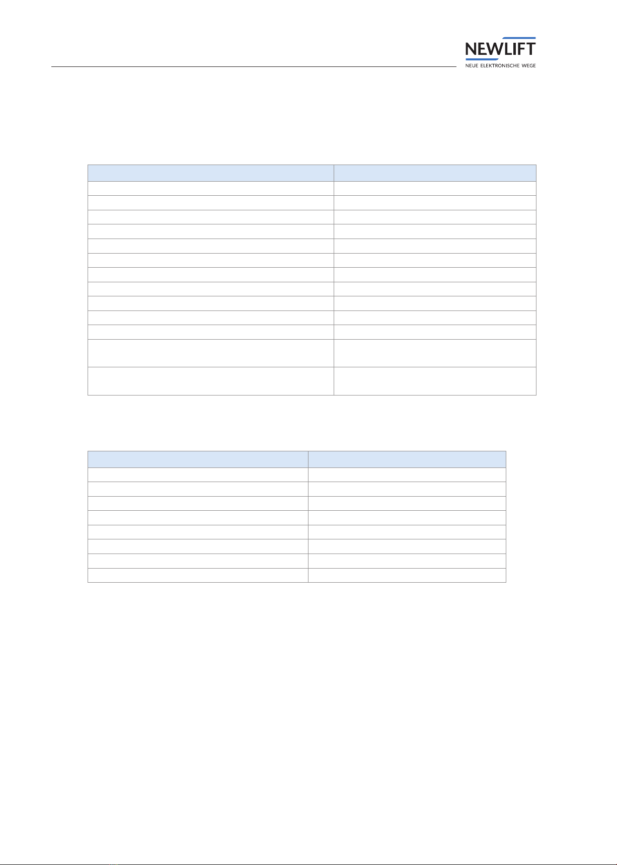
3.1 General
DMT-TFT 110
Dimensions 146mm x 106mm x 30mm
Display area (active area) 110 mm x 67 mm
Resolution 800 x 480
Bits per pixel 24
Supply voltage 24 V DC ±10%
Typical power consumption 150 mA (without button acknowledgement)
Outputs Short circuit-proof
Weight 187 g
Max. output voltage 24 V DC
Max. output current 150 mA
Starting current 600 mA for approx. 40 ms
Temperature range:
Storage & transport / operation
-20 – +70 °C / ±0 – +60 °C
Relative humidity:
Storage & transport / operation (non-condensing)
+5 – +95 % / +15 – +85 %
3.2 Functional
Function DMT-TFT 110
Display 5 inch
Display screen Separate
Installation orientation 0°, 90°, 180°, 270°
Prog. inputs/outputs 8
Prog. inputs 2
Destino SAM YES
USB support USB, MiniUSB
Application area Landing call terminal
Technical data
Manual DMT-TFT.110 9
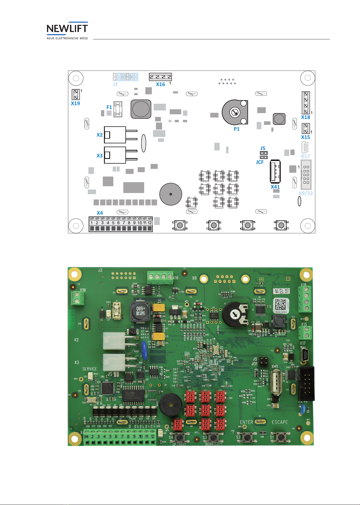
3.3 Pin assignment
ESCAPE
ENTERDOWN/LEFTUP/RIGHT
X2
X3
X4
X16
X41
X18
X15
X17
X9/32
JCF
J5
P1
F1
X19
J3
LD5
JS
LD2
LD1
BUZZ1
X25
X21
X24
X22 X23
X26
X28 X29
X27
Rear view – schematic diagram
Rear view
Technical data
10 Manual DMT-TFT.110
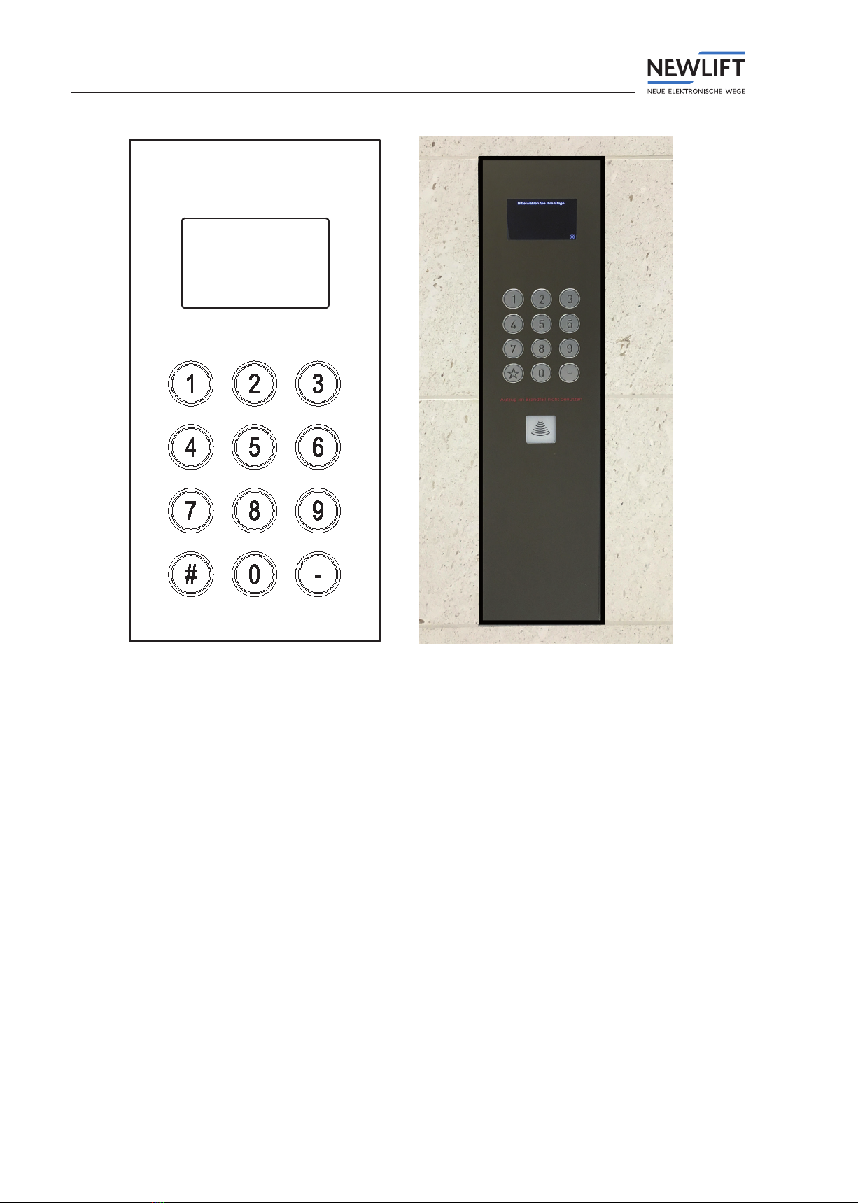
Front view – schematic diagram Front view – example of installation and design

Technical data
Manual DMT-TFT.110 11
3.4 Wiring
Irreparable damage to the electronics!
Make sure that the panel is earthed.
3.4.1 Standard wiring
Visual acknowledgement is only possible if button acknowledgement functions independently.
Example of button with decoupled acknowledgement
3.4.2 Wiring for individual buttons
With this wiring type, the buttons are connected to signal lines 0 to 7 (optionally with programmable
inputs) and GND.
GND (X4.10)
Signal 0 (X4.2) 0
Signal 1 (X4.3) 1
Signal 2 (X4.4) 2
Signal 3 (X4.5) 3
Signal 4 (X4.6) 4
Signal 5 (X4.7) 5
Signal 6 (X4.11) 6
Signal 7 (X4.12) 7
Prog. input (X4.8) Optional
Prog. input (X4.9) Optional
4.2 4.3 4.4 4.5 4.6 4.7 4.11 4.12
NO
0
4.8 4.9
Optional
CNO
1
CNO
2
CNO
3
CNO
4
CNO
5
CNO
6
CNO
7
C
TFT110
4.10
GND
prog.E
1
prog.E
2
Example of 1 x 8 (+2) wiring
Technical data
12 Manual DMT-TFT.110
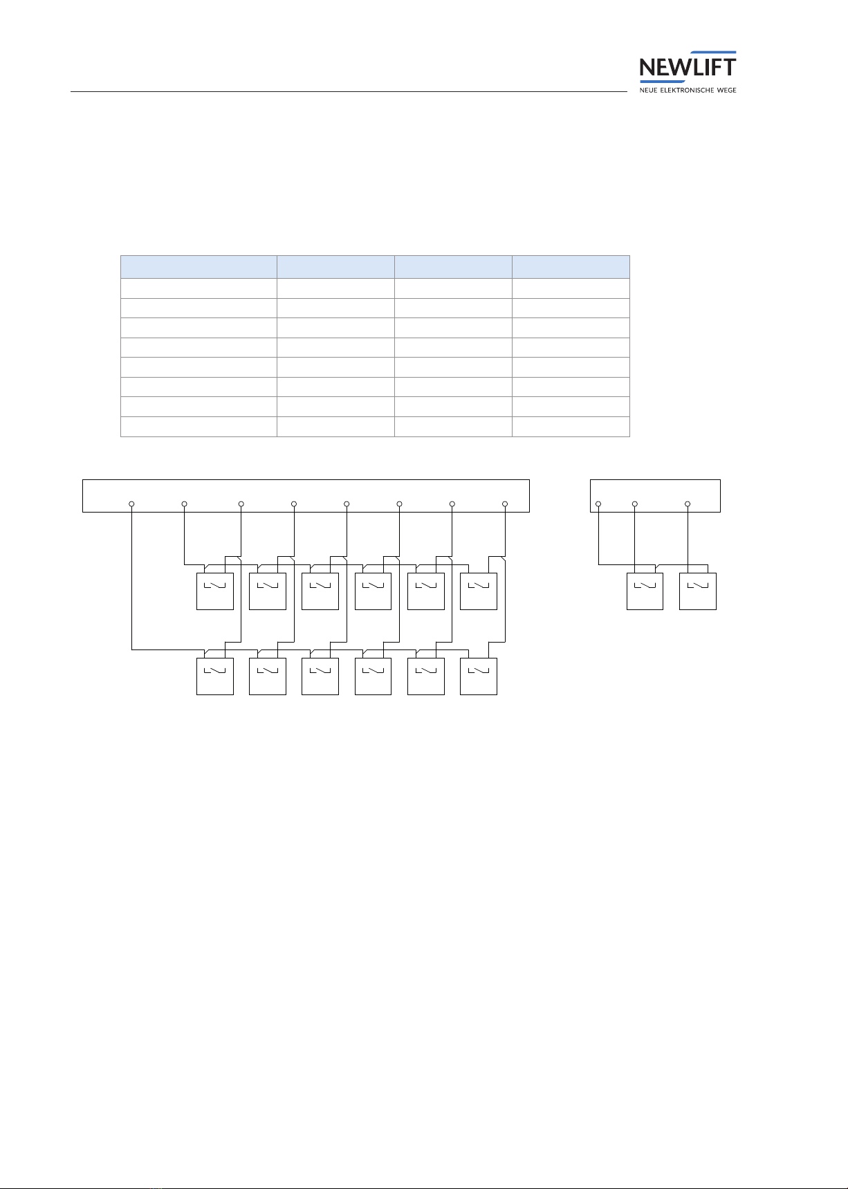
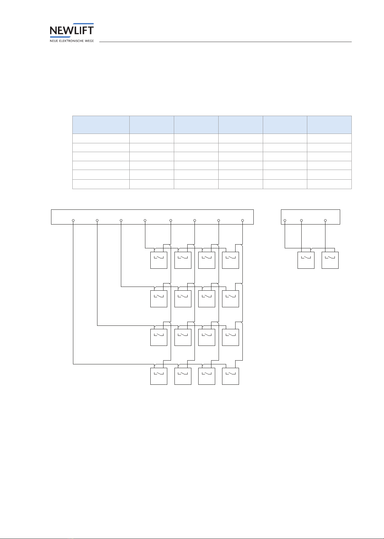
3.4.3 Wiring for 2 x 6 matrix
With this wiring type, there are two enable lines and six signal lines.
The enable lines are permanently assigned to X4.2 and X4.3, and the signal lines to X4.4, X4.5, X4.6,
X4.7, X4.11 and X4.12.
Enable 1 (X4.2) Enable 0 (X4.3) GND (X4.10)
Signal 2 (X4.4) 6 0 -
Signal 3 (X4.5) 7 1 -
Signal 4 (X4.6) 8 2 -
Signal 5 (X4.7) 9 3 -
Signal 6 (X4.11) * 4 -
Signal 7 (X4.12) # 5 -
Prog. input (X4.2) - - Optional
Prog. input (X4.2) - - Optional
4.2 4.3 4.4 4.5
C
CC
9
51
TFT110
NO
NONO
4.6
CC
C
6
2
NONO
NO
4.7
CC
C
*7
3
NONO
NO
4.11
C
C
#8
4
NO
NO
4.12 4.10
GND
4.8
prog.E
1
Optional
4.9
prog.E
2
NO
0
C
Example of 2 x 6 (+2) wiring
Technical data
Manual DMT-TFT.110 13
3.4.4 Wiring for 4 x 4 matrix
With this wiring type, there are four enable lines and four signal lines.
The enable lines are permanently assigned to X4.2 and X4.3, X4.4. and X4.5 and the signal lines to X4.6,
X4.7, X4.11 and X4.12.
Enable 3
(X4.2)
Enable 2
(X4.3)
Enable 1
(X4.4)
Enable 0
(X4.5)
GND (X4.10)
Signal 4 (X4.6) 1 5 9 12 -
Signal 5 (X4.7) 2 6 0 13 -
Signal 6 (X4.11) 3 7 10 14 -
Signal 7 (X4.12) 4 8 11 15 -
Prog. input (X4.2) ----Optional
Prog. input (X4.2) ----Optional
4.2
CNO
4.3
C
1
NO
4.4
C
2
NO
4.5
C
3
NO
TFT110
4.6
CNO
4.7
C
5
NO
4.11
C
6
NO
4.12
C
7
NO
C
C
12
9
NO
NO
C
C
13
0
NO
NO
C
C
14
10
NO
NO
C
C
15
11
NO
NO
4
8
4.10
GND
4.8
prog.E
1
Optional
4.9
prog.E
2
Example of 4 x 4 (+2) wiring

Installation and commissioning
14 Manual DMT-TFT.110
4 Installation and commissioning
The DMT-TFT.110 may only be installed by a trained electrician.
Information on the qualications required by the lift engineer can be found in the manual FST Installation &
Commissioning (See chapter “1.3 Further information” on page 6).
Electrostatic charging
›Keep the electronic assembly in its original packaging until installation to prevent damage.
›Before opening the original packaging, a static discharge must be performed!
To do this, touch a grounded piece of metal.
›During work on electronic assemblies, periodically repeat this discharge procedure!
›Equip all bus inputs/outputs not in use with a terminal resistor (terminator) to prevent malfunctions.
4.1 Unpacking
►Remove the packaging material completely.
►Peel the protective lm off the display screen.
After installation, it is no longer possible to remove the protective lm.
4.2 Installation
The clarity of the display depends on the viewing angle; the installation position of the display is
therefore critical in achieving an optimum result.
►Determine the installation position before mounting.
►Make sure that the installation position matches the orientation of the display.
DMT-TFT.110 – The display is not positioned symmetrically on the assembly.
Pressure or tension can damage the circuit board.
►Do not overtighten the nuts!

Installation and commissioning
Manual DMT-TFT.110 15
4.2.1 Installation dimensions
Unless otherwise specied in the installation drawing: All tolerances +/- 0.1 mm.
To allow cable installation, make sure that a gap of 5 mm to adjacent parts is provided on all four sides of the
DMT-TFT.110.
Provide additional space for the cables at connection X4.
Side view
Panel
Spacer sleeve
Nut
Display screen
DMT-TFT.110
Installation depth: 30 mm
2,0 mm
2,0 mm2,0 mm
8,5 mm
1,6 mm
14,9 mm
Threaded pin M3 x 16 mm in panel
Installation drawing – side view in installed state.
Installation and commissioning
16 Manual DMT-TFT.110
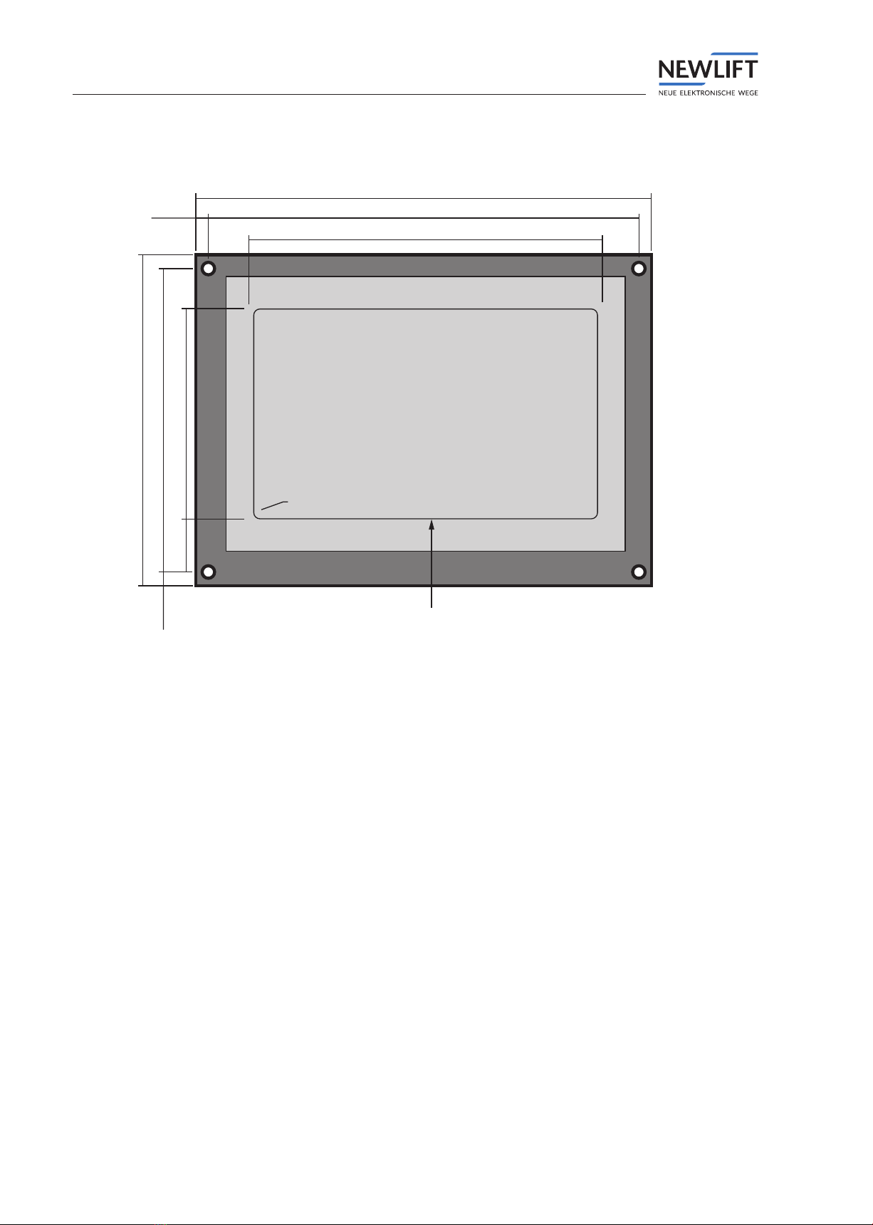
Front view
138,0mm
110,5mm
67,5mm
97,2mm
17mm
146,0mm
106,0mm
radius
2mm
4,4mm
top
top
4,0mm
14,5mm
display area
Installation drawing – front view with display screen mounted.
The display screen is included in the delivery contents.

Installation and commissioning
Manual DMT-TFT.110 17
4.2.2 Adapting installation position
►In the main menu, select the Basic settings icon.
The Basic settings window opens.
►Select the icon that corresponds to the installation position of your panel.
Horizontal installation, normal installa-
tion position.
The LON bus connections are located on
the left.
Horizontal installation, rotated by 180°.
The LON bus connections are on the
right.
Vertical installation, normal installation
position.
The LON bus connections are located at
the bottom.
.
Vertical installation, rotated by 180°.
The LON bus connections are at the top.

Software
18 Manual DMT-TFT.110
5 Software
5.1 Destination call entry system
The destination call system is the combination of several FST controllers to form a group. The group is
controlled by a group controller (GST) with destination call software.
In the case of destination control, the calls are processed differently to conventional groups. Whereas
conventional groups only nd out their destinations when the passengers enter the car, with a
destination call system the destination is specied in advance from so-called terminals. With the aid of
the destination call group controller, this allows the lift operation plan to be better coordinated and the
passengers to reach their destination more quickly.
Destination call
A destination call comprises three steps:
›Entry of the destination call
›Query sent to the group controller
›Reply from the group controller
Destination call terminal
The destination call terminal comprises three conguration blocks:
›location information, consisting of
»oor
»door side
»terminal ID
›installation-specic conguration, e.g.
»shaft information
»oor designations
»doors
»button assignment for destination call terminal
»special functions, etc.
›customer-specic display
NEW LIFT offers various terminal types.
Software
Manual DMT-TFT.110 19
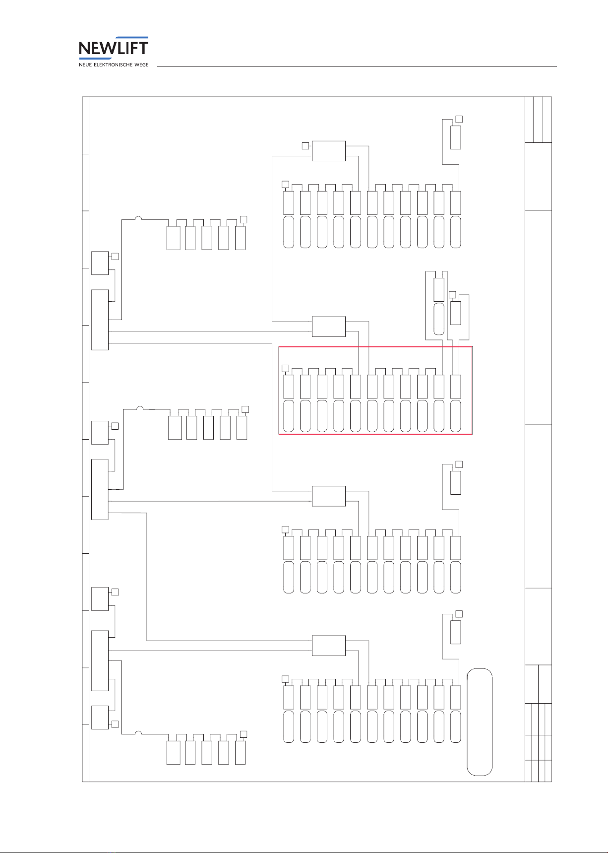
© Alle Rechte vorbehalten
NEW Lift - Steuerungsbau GmbH
Lochhamer Schlag
82166 Gräfelfing order
bus topologie factory no.:
Destino
=
+
page
Aufzug
75
draw:
date:
AB
18.04.2018
change:
date: name:
change:
change: 92from
IK = inspection cabinet
FK = car
legend
typ / bus / door / floor / FST
S / 0 / A / 0 / A
FK
FK
FK
IK
IK
FSM-2
SAM
FPM-2
TFT.110
LCS
X12
T
black
(0,5)
yellow
(5)
black
(0,5)
black
(0,5)
trailing cable 57,5 m
T
EM
EAZ 256
S/0/A/10/A
S/0/A/09/A
S/0/A/08/A
S/0/A/07/A
S/0/A/06/A
S/0/A/05/A
S/0/A/04/A
S/0/A/03/A
S/0/A/02/A
S/0/A/01/A
S/0/A/00/A
1
ADM-S
ADM-S
ADM-S
ADM-S
ADM-S
ADM-S
ADM-S
ADM-S
ADM-S
ADM-S
ADM-S
X3
T
yellow
(5)
yellow
(5)
yellow
(5)
yellow
(5)
yellow
(5)
yellow
(5)
yellow
(5)
yellow
(5)
yellow
(5)
blue
(35)
yellow
FST-2XT - A
X30
(5)
X5
secondary
(output)
X1
X3
repeater
board
primary
(input)
X5
X2
X4
(5)
red
(50)
X6
LSG
1
T
white
(3)
X11
GST
T
X10
destination call (Destino)
Tableaus
DMT-TFT.110
green
(10)
X6
X5
secondary
(output)
X1
X3
repeater
board
primary
(input)
X5
X2
X4
(10)
FST-2XT - C
X30
CUS
S/2/A/01/C
X3
T
(0,5)
ADM-S
1
black
(0,5)
green
(10)
EM
EAZ 256
T
FK
IK
FK
FK
FK
FSM-2
FPM-2
TFT
TFT
FPM-2
X12
trailing cable 52,5 m
T
yellow
(5)
(0,5)
S/2/A/10/C
S/2/A/09/C
S/2/A/08/C
S/2/A/07/C
S/2/A/06/C
S/2/A/05/C
S/2/A/04/C
S/2/A/03/C
S/2/A/02/C
S/2/A/01/C
S/2/A/00/C
(0,5)
blue
(7)
ADM-S
ADM-S
ADM-S
ADM-S
ADM-S
ADM-S
ADM-S
ADM-S
ADM-S
ADM-S
ADM-S
T
yellow
(5)
yellow
(5)
yellow
(5)
yellow
(5)
yellow
(5)
yellow
(5)
yellow
(5)
yellow
(5)
yellow
(5)
(5)
X5
secondary
(output)
X1
X3
repeater
board
primary
(input)
blue
(7)
X2
X4
T
yellow
(5)
LSG T
white
(3)
S/1/A/10/B
S/1/A/09/B
S/1/A/08/B
S/1/A/07/B
S/1/A/06/B
S/1/A/05/B
S/1/A/04/B
S/1/A/03/B
S/1/A/02/B
S/1/A/01/B
S/1/A/00/B
ADM-S
ADM-S
ADM-S
ADM-S
ADM-S
ADM-S
ADM-S
ADM-S
ADM-S
ADM-S
ADM-S
T
yellow
(5)
yellow
(5)
yellow
(5)
yellow
(5)
yellow
(5)
yellow
(5)
yellow
(5)
yellow
(5)
yellow
(5)
X6
blue
(35)
(5)
X5
secondary
(output)
X1
X3
repeater
board
primary
(input)
X5
X2
X4
yellow
(5)
FST-2XT - B
X30
LSG
X3
T
white
(3)
1
FK
FK
FK
IK
IK
FSM-2
EM
EAZ 256
SAM
FPM-2
TFT.110
LCS
T
trailing cable 57,5 m
X12
T
black
(0,5)
yellow
(5)
black
(0,5)
black
(0,5)
red
(50)
T/2/A/10/C
T/2/A/09/C
T/2/A/08/C
T/2/A/07/C
T/2/A/06/C
T/2/A/05/C
T/2/A/04/C
T/2/A/03/C
T/2/A/02/C
T/2/A/01/C
T/2/A/00/C
TFT.110
TFT.110
TFT.110
TFT.110
TFT.110
TFT.110
TFT.110
TFT.110
TFT.110
TFT.110
TFT.110
T
green
(10)
green
(10)
green
(10)
green
(10)
green
(10)
green
(10)
green
(10)
green
(10)
123456789101112
Example circuit

Software
20 Manual DMT-TFT.110
5.2 Card reader system
The DMT-TFT.110 terminal has a central and a local card reader system.
Central card reader system
The central card reader system uses a central card reader evaluation unit (ZAE). The system allows
individual oors to be enabled using a card. The card is read out using a card reader and evaluated via
a server. The server communicates with the GST controller via a protocol. The GST controller forwards
the information via LON to the terminal.
third-party products
NEW LIFT products
Central
evaluation unit
Local card reader system
The local card reader system uses card readers that are directly connected to the DMT-TFT.110
terminal. The system allows individual oors to be enabled using a card that is read out and evaluated
via the card reader. The card reader informs the terminal of the enable via a contact.
In other words, as soon as the contact switches, the oor enable mask congured in the terminal
becomes active.
See “Badge enable mask 1” on page 24
Presets
In card reader mode, it is possible to preset oor enables on the terminal. These presets serve as the
basic settings for the terminal. Received enables/locks extend/reduce the destination call options.
Table of contents
Popular Touch Terminal manuals by other brands

Sharp
Sharp UP-5350 installation manual

Tailwind
Tailwind FlexiPole Connect Quick installation guide

Allen-Bradley
Allen-Bradley PanelView Plus 7 installation instructions

DIEBOLD NIXDORF
DIEBOLD NIXDORF BEETLE /iSCAN EASY Non Cash installation manual

Motorola
Motorola IRRInet-XL owner's manual

Worth Data
Worth Data 7100 RF Terminal Series owner's manual


