New Ridge Technologies NRT-2500 User manual

NRT-2500
User Manual

Table of Content
Chapter ....................................................................................... Page
!""
"#$!
%&" '
$()
*
*+,+-
+"+
*() .
# / 0
#) 1
% .
2 1
03). '
145 '
04
0#&22
06$7#
0+++&
08
0# &
0%#)$&
0%
0%*&
0%#)&
0%%# /93).& %
0% .& %
0%02& %
0%145& %
0#&2&# )
1 !) 0
!"::& )$%

1. Introduction
" 2. & $;/ )$ $ /
) )) " " ; ).$
)/<
*
# /
#)
% .
#$2.,#(2-
0 45,;-
" "= " = " $ ; )
$;/<
4$:/().==/""!==
)$
3#2*" ").)
24 $ "3#2
% 4)*" "").)"43&)
$$/*" )
43&);)$$/*
!)//) $ 5
2. Getting Familiar with the NRT-2 00
"$$"")!!")!> ))
"!
!"::& )$%
Figure 1: Front view of the NRT-2500

"$""<
?3&)$ %?4&=
%43&,6&-)
+":4
% #
:*>(,$" >=)$$$-
0 34&)@"!,)$-
#""$)$"=/"
!"::& )%$%
Figure 2: Rear view of the NRT-2500
Figure 4: Power and communications ports
on the ack of the NRT-2500
Figure 3: Analog connections (BNC) to the
4 ADC channels on the NRT-2500

3. Installing the NRT-2 00 Software
"*=!"/*"NRT-2500-2.0.0.6 Setup.exe
"$!!")"!0""
!"::& )$%
Figure 6: Initial setup screen; Click NEXT to continue.
Figure 5: Rear of NRT-25xx ready for operation with a single analog input in stand-alone
mode.

!"::& )0$%
Figure 7: Select the optional components you would like to e installed y checking or
unchecking the ox next to the optional components list. Click NEXT to continue.
Figure 8: Select the location to which you want the installer to install the NRT-2500 application.
Click on BROWSE to navigate and select a folder different from the default folder. Click
INSTALL to continue.

!"::& )1$%
Figure 9: The installer will copy the components required for the NRT-2500 application and will
create an entry in the start menu and place a shortcut on the desktop if you have selected to do
so.
Figure 10: Once the installation is completed, click on the FINISH utton to end the installation
process.

A )/$ );"$!"!
""$! )!))$
4. Connecting to the NRT-2 00
& $"=#+"3/*"
"("!!)!//"
))!*,-
!"::& )'$%
Figure 11: A new entry is now availa le on the start menu and if selected, as well as a shortcut
on the desktop (optional).
Figure 12: Select the communication type (Serial or LAN) and port. Click on the COM# or the
LAN IP to see a list of availa le connections. Click on the refresh arrow to refresh the list. Click
CONNECT to esta lish communication with the NRT-2500.

&*Bome=$" /$"" )"
) $ !=7 "/!""
)/*"3/,%-
!"::& )C$%
Figure 13: Once the communication etween the computer ant the NRT-2500 was esta lished
the NRT-2500 will default to Tracker Mode and the tracker screen will show up. The values
showed y the GUI are the last values that were used in the GUI.
Figure 14: The NRT-2500 GUI Home screen. The screen shows the serial Num er of the unit, the
firmware version, model of the unit, and the communication type and port in use. Click the
Disconnect utton to terminate the connection etween the computer and the NRT-2500.

. Modes of Operation
""0 $)" /$ " # /
"$$",-"0 $)<
•*
•# /
•#)
• .
•2
•3).
•45
.1 Tracker Mode
"$ )""*,0-*"
! $)DHy rid Angle Only. /!"! /*"
"/*$" !/Angle Only ,"*
)" !"!) .) ) 9,) 9%
!/-Hy rid ,"*"))" !"$
) =4"Averages" /$43&"
)!=))"Threshold" ", ?-"!
)$"" "Delay" E/!)$ "
"=$"),-") )";) )
F) !" $" "Minimize
Maximize"=$"*+,+-
!"::& )$%
Figure 15: The Mode Selector ar. Click on the mode you would like to select, the GUI screen
will adjust to the selected mode.

")$"*/)/*"Running"
!";$"*" "! /Idle ,
1-&*" /3:+ "*)"!
!Running
!"::& )$%
Figure 17: Idle in Tracker mode.
Figure 16: Select the desired mode of operation from the left panel of the GUI.

.1.1 Tracking Error Function (TEF)
"*+="$%6&)"/*$"
$/*"+/$$$$/*"
" $/* " " * ) " / ) . $ / ) " +
)=$;/!". )*$
= "
.1.2 Editing the TEF
"*+*"Optimizer/")"$
"!"Tracker mode""!'!"!)""
) "!"!)") ""=/"
"+!") "
/*")=,"!1-G*"*$"
/") .*"Next/.") .
!"::& )$%
Figure 18: The Tracking Error Function (TEF) screen of the GUI. Use this screen to edit the
feed ack signal used for the NRT-2500 tracking mode. Change the values of the coefficients A,
B, C and N to construct the desired TEF, according to the formula shown at the top of the TEF
editor. Click NEXT to run the Optimizer, or choose Tracker from the mode selector ar to go
ack.

.1.3 Tracking Optimizer
"*" ) /G"""B!=G%
) ) ."*/"="$""
/Tracki g Optimizer"$"/$=$2222%
"" / ." /$ *$/"
*""
"$)") .) "$=/"+
!""*$/$,4-4$" ;
=$"+ " $"+=)"
" !!,"! -!/)4 $"+H
" $ """=;" /$ )
"" " /! )"!"
"""3="/")/= )
":!)) $"+/+ + ;)=
"" ! )$/"$!""+ + ;
" " ))) / " ! $ / $ / !"
$5$"+) .) )/)C""0
!"::& )$%
Figure 19: The TEF Optimizer – Step 1, Auto Range: the unit will auto range the input level of
the Tracking Error Signal and acquire a histogram of that signal to visualize the system ehavior
and allow the user to etter define the level at which the system would e considered to e elow
the desired...

!"::& )%$%
Figure 20: The TEF Optimizer – Step 2, Setting the Error Level Threshold : The graph shows the
frequency (num er of occurrences) as a function of the TEF value. Slide the cursor to select the
TEF error-threshold value. The GUI will show the TEF Value at the cursor location, the Integral
Value i.e. the normalized integral value of the TEF and the Histogram Value (frequency) at the
cursor location. Press Next to continue using the selected threshold value. Press Acquire
Histogram to collect new histogram data or Previous to return to the screen shown in Figure 18
in order to modify the TEF function.
Figure 21: TEF optimizer Step 3, Select the num er of steps per optimization iteration. Confirm
the value of the Error Threshold, select Minimize or Maximize the TEF. and then press OK to
start the Optimizer execution.

!"::& )$%
Figure 23: TEF Optimizer step 5 – once the Optimizer execution is terminated, the 4 optimized
parameters are shown in the lower part of the window. The user may choose etween 3 options:
1. Save Parameters to NRT: update the NRT-2500 memory. 2. Export as CSV: save the data to a
CSV file, or 3. Previous: ignore the parameters calculated in the optimizer run and go ack to
set new optimization parameters.
Figure 22: TEF Optimizer step 4 - While the optimizer is running, the set of 4 optimization
parameters is displayed together with the num er of tracking errors measured. Each iteration
value can e viewed in the Iteration Data ox. Terminate the execution of the Optimizer program
y clicking on any of the 3 uttons elow the graphic screen.

$"="$!!!))$ )" OK
/"!/= )$"/)!"$+;
)"))
.2 Scrambler Mode
/ "#(2""$!"" /
$/"")*$""/ "/""
)./I;IJI;I
!"::& )0$%
Figure 24: Scram ler mode: Set the scram ling speed y setting the value of Rmode. The
Rayleigh distri ution scales linearly with the value of Rmode.
Figure 25: Stop the Scram ler execution y clicking on the RUNNING indicator. The indicator
will turn am er and read IDLE. (You may also set the Rmode speed to 0 to stop the Scram ler.)

.3 Spinner Mode
#) "F F"$$ Half-Wave-Plate ,BA2-
/!!KLKPolarization-Controllers,2&F-")$"BA2")
$"BA2"!2&F/MInputNMOutputN)="
")$"#(2,)-)/",-"$"
#)BA2,-"#(2)"#)FBA2A$"#)F/
"=$5B."#(2)!/ ; $"
)."=BA2,6$")"BA2)."
#(2$#)$5-4=$5$OB.P" ;
)$" $ J$ " $ " )!,/"5$"
2Q)"-%J$ "//!"= $ , ; - #(2
>#) f
NRT-2 00
Spinner Setting
[kHz]
Maximum E-field rotation
(in real space)
[rad/sec]
Maximum Power Rotation
(Equator of Poincaré sphere)
[rad/sec]
f = f x 2π = f x 4π
0 0
'
%
'
CC
C'
1C0
C'C
C1C
C0' 1 1
1C'
C
'1
' %
%11%0 0
000 % '
1 %1C C%%1'
!"::& )1$%

"#)$5""Frequency =!""!$1B.
;"Output2&""$#)FG, "
#)FG)"5$"2Q)"-""=$
"#)F";$/G"Input2&, ""
)FG!!""5$"2Q)""
"!"")"BA2-7 "*")>!!
)=$"$"!=)"))2&/"G"
$7 "3:+""#)F
A""=$"BA2G"=)"SAVE/
"2&F" 4!/!))<" LOAD /7
!""2&""BA2G2"LOAD/!"=
)"BA2G"=#0""1$
;)$"#) 3$
"Lock//"2&F"SaveLoad/!))"Lock/!
Unlock/"Drift!))"$)!"
"BA2G&*"$/;$ %$)<
@$
4 #)4; @ $ " BA2 G =D " ) ) = !" "
=,")2&-
#)4;@$"BA2GD"))
,")2&-
% 6"@&"/""=$"BA2G
!"::& )'$%
Figure 26: Spinner mode: From the default GUI screen the user can control the spinner speed,
the HWP trajectory elevation and orientation, and can set the NRT-2500 to Idle.

!"::& )C$%
Figure 27: Pressing the SAVE utton will store the settings of the input and output polarization
controllers. Once you press SAVE, the LOAD and Lock uttons will appear.
Figure 28: You can now change the sliders positions. Pressing the Load utton will restore the
values to the values saved efore the changes have een made. Pressing the Lock utton, the
plates sliders and indicators as well as the Save and Load uttons will e grayed out and locked.
The Drift mode selector and speed will appear on the ottom of the GUI window (see Figure 29).

!"::& )$%
Figure 29: The Drift mode will read None (no drift). Press on the Drift utton to select the
desired drift mode. Choose etween None, Along Spin Axis, Rotate Spin Axis or Both (see Figure
30). You can also change the drift rate etween the non cali rated drift rates 1-10.
Figure 30: The drift modes and drift speed.
Table of contents
Popular Controllers manuals by other brands
Nevco
Nevco 816 Operator instructions
Remote Control Systems
Remote Control Systems ALPHA-3-LO instructions

Epson
Epson S2R72A11 Application note
Creative Lighting Solutions
Creative Lighting Solutions Control Freak eDIDIO S10 user manual
DriSteem
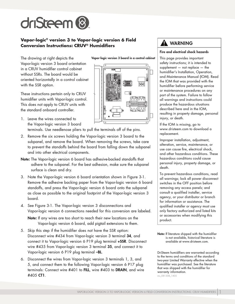
DriSteem VAPOR-LOGIC 3 Conversion instructions
DMX4ALL
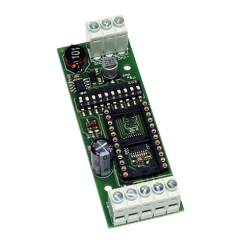
DMX4ALL DMX-LED-Dimmer CC1 user manual

Omron
Omron SCARA YRCX Series Programming manual
Vortice
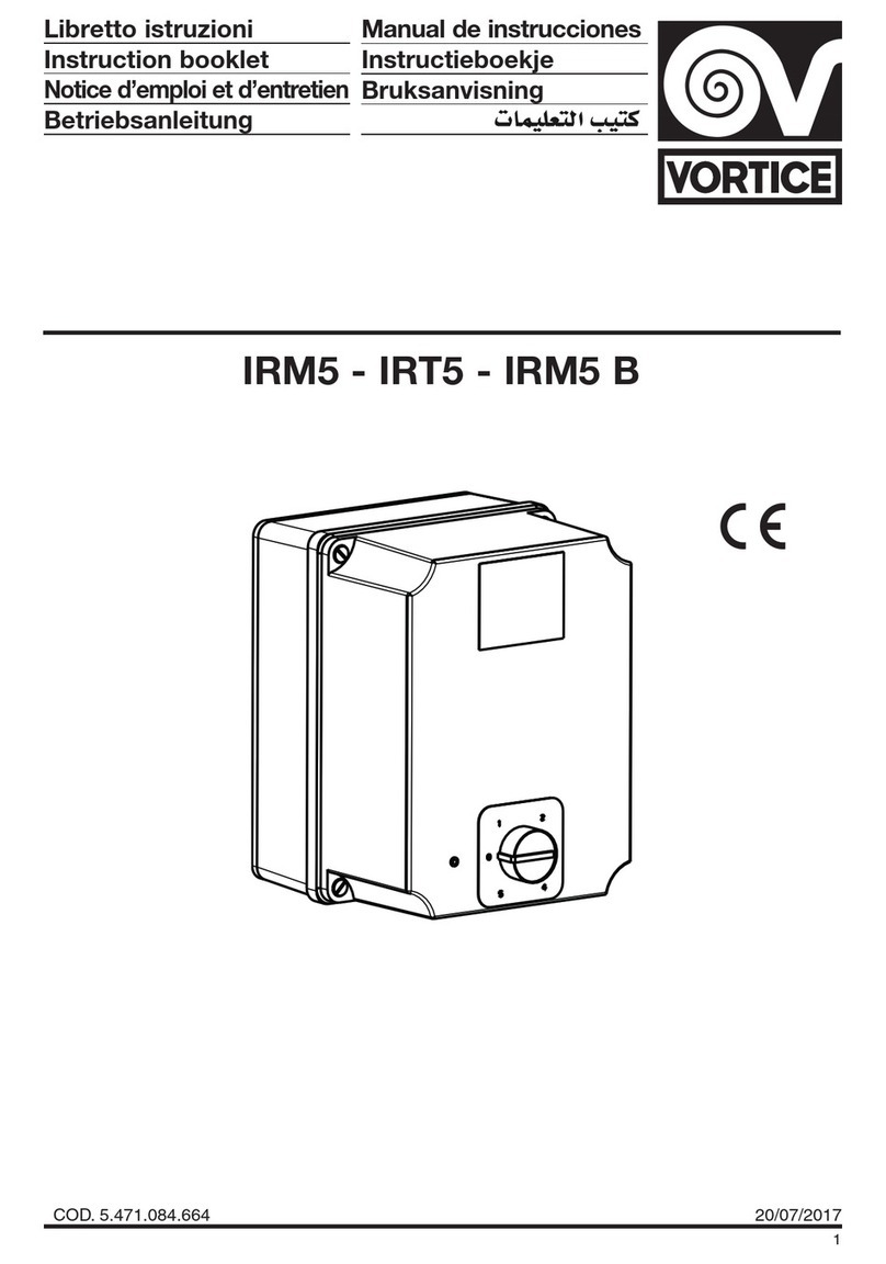
Vortice IRM5 Series Instruction booklet

Schrack Technik
Schrack Technik LAKS Series Design guide
DH Instruments
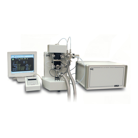
DH Instruments FPG8601 Operation and maintenance manual

Oppermann Regelgeräte
Oppermann Regelgeräte ABAV-S3 quick start guide

Osram
Osram OT EASY 60 II operating instructions
