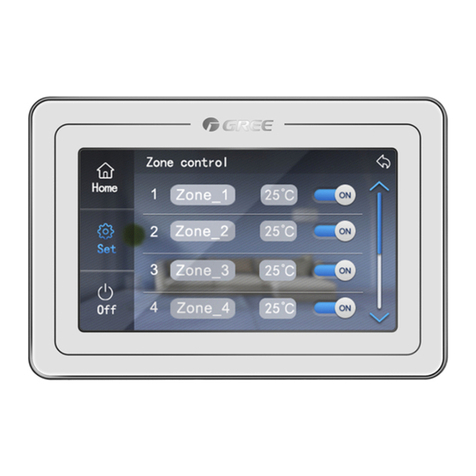
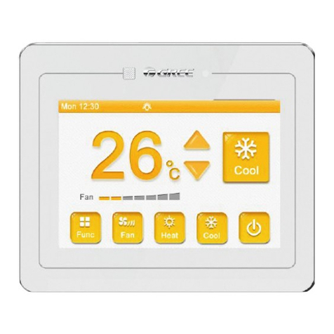
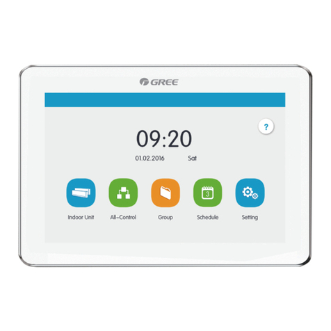
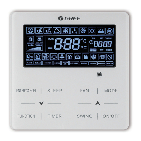
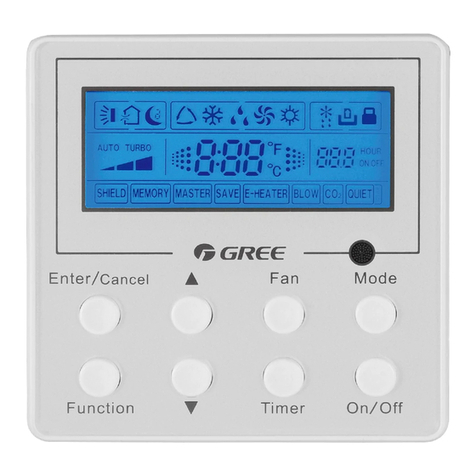
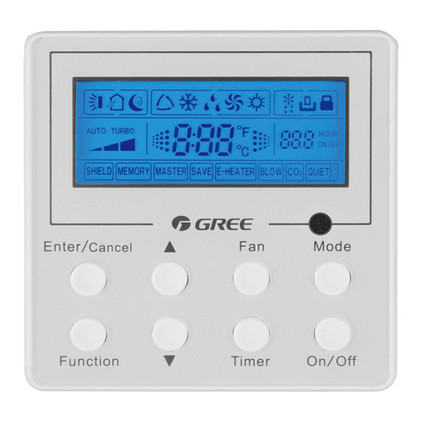
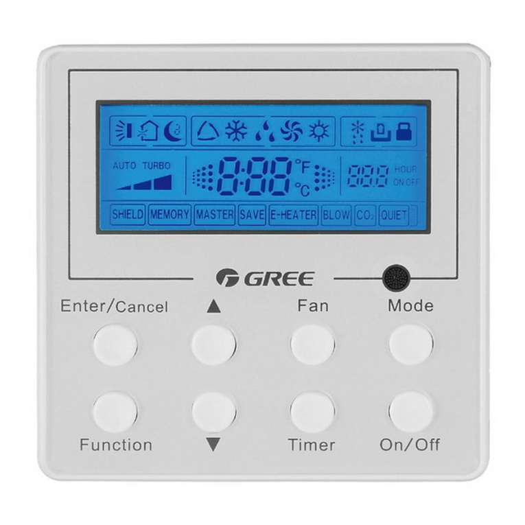
Gree CE50-24/E User manual

Change for life
Smart Zone Controller
Commercial Air Conditioners
Installation Manual
Thank you for choosing Commercial Air Conditioners, please read this owner’s manual
carefully before operation and retain it for future reference.
GREE reserves the right to interpret this manual which will be subject to any change due
to product improvement without further notice.
GREE Electric Appliances, Inc. of Zhuhai reserves the nal right to interpret this manual.

CONTENTS
1 Safety Precautions ......................................................................................... 1
2 General Introduction........................................................................................ 2
2.1 Function Introduction.................................................................................. 2
2.2 Communication Network ............................................................................ 3
3 LCD ................................................................................................................. 4
3.1 Outline of the LCD...................................................................................... 4
3.2 Introduction to Symbols on the LCD........................................................... 4
4 Buttons ........................................................................................................... 5
4.1 Outline of Buttons....................................................................................... 5
4.2 Introduction to the Function of Buttons....................................................... 6
5 Installation and Debugging.............................................................................. 7
5.1 Installation .................................................................................................. 7
5.2 Unit Matching ........................................................................................... 10
5.3 Debugging and Viewing the Port No. and the Indoor Unit Address.......... 11
5.4 Labeling.................................................................................................... 12
6 Control Flow Chart......................................................................................... 13
7 Viewing of the Running Status of the Indoor Unit and Control Mode ............ 13
7.1 Viewing of the Running Status of the Indoor Unit..................................... 13
7.2 Control Mode............................................................................................ 14
7.3 Control Setting.......................................................................................... 16
8 Error Display.................................................................................................. 34

Floor Ceiling Air-Conditioning Unit
1
1 Safety Precautions
WARNING! This mark indicates procedures which, if improperly performed, might lead to
the death or serious injury of the user.
CAUTION! This mark indicates procedures which, if improperly performed, might possibly
result in personal harm to the user, or damage to property.
WARNING!
① .
For operating the air conditioner pleasantly, install it as outlined in this installation manual.
② .
Connect the indoor unit and outdoor unit with the room air conditioner piping and
cord available from our standard parts. This installation manual describes the correct
connections using the installation set available from our standard parts.
③ .
Installation work must be performed in accordance with national wiring standards by
authorized personnel only.
④ .
If refrigerant leaks while work is being carried out, ventilate the area. If the refrigerant
comes in contact with a ame, it produces toxic gas.
⑤ .
Do not power on until all installation work is complete.
⑥ .
During installation, make sure that the refrigerant pipe is attached rmly before you run the
compressor.
Do not operate the compressor under the condition of refrigerant piping not attached properly with
2-way or 3-way valve open.
This may cause abnormal pressure in the refrigeration cycle that leads to breakage and even
injury.
⑦ .
During the pump-down operation, make sure that the compressor is turned off before you
remove the refrigerant piping.
Do not remove the connection pipe while the compressor is in operation with 2-way or 3-way
valve open.
This may cause abnormal pressure in the refrigerant cycle that leads to breakage and even injury.
⑧ .
When installing and relocating the air conditioner, do not mix gases other than the specied
refrigerant (R410A) to enter the refrigerant cycle.
If air or other gas enters the refrigerant cycle, the pressure inside the cycle will rise to an
abnormally high value and cause breakage, injury, etc.

Floor Ceiling Air-Conditioning Unit
2
2 General Introduction
2.1 Function Introduction
This smart zone controller is intended for VRF, free-match and ducttype unit, capable of
controlling up to 3 sets of multi VRF units and multi sets of duct type/ free match units with
maximum 16 indoor units.
Through this smart zone controller, it is available to view and control those running parameters
of the indoor unit, including on/off, running mode, fan speed etc, and also perform the single control
and centralized control, further, it also can set the weekly timer and long-distance shielding to
realize convenient control to the air conditioning system.
a. Single control: it is intended to control the running parameters of a designated indoor unit
individually.
b. Centralized control: it is intended to control the running parameters of all indoor units at the
same time.
c. Shielding under single or centralized control: it is intended to shield the running parameter of
the indoor unit.
d. Weekly timer under single or centralized control: it is intended to set when to start/stop the
unit through long-distance control.
e. Clock: it is intended to set and display the weekday, hour and minute.
After the debugging to the controller is finished, it can check the on-line indoor units and
display the parameter setting of the current running mode, set temperature, fan speed, weekly
timer, shielding function etc. When some error occurs, the error symbol and the error code will be
displayed to warn a quick maintenance.
This smart zone controller can be connected to the unit through the communication line without
the need of the communication module, which can extremely ease and simplify the installation.
This smart zone controller can be integrated with the long-distance monitoring system and the
centralized controller (it indicates the controller that should be equipped with the communication
module) and the control of the long-distance monitoring system and the centralized controller takes
priority over that of the smart zone controller.

Floor Ceiling Air-Conditioning Unit
3
2.2 Communication Network
2.2.1 Units Connection
Max.16
VRFVRFVRF
SmartZoneController
DuctType/ FreeMatch
Wired
Controller
Max.16
Max.16
Max.16
Port 1(VRF)
Port 2(VRF)
Port 3(VRF)
Port 4 (Duct Type/ FreeMatch)
Max. 16
Wired
Controller
Wired
Controller
DuctType/ FreeMatchDuctType/ FreeMatch
Fig.2.1 Unit Connection Diagram
Note: the smart zone controller can connect with maximum three sets of multi VRF units and
multiple duct type units, however, the total of the indoor units of all four ports can not exceed 16.
2.2.2 Integration of the Smart Zone Controller and Long-distance Monitoring System/
Centralized Controller
Max.16
Centralized Controller
PC & Long-Distance Monitoring System
Max.16 Max.16
Max.16
Port 1 (VRF)
Port 2 (VRF)
Port 3 (VRF)
(Max.16 indoor units)
Smart Zone Controller
Communication Module
or
VRFV RFVRF
Duct Type / Free Match
Wired Controller
Max.16
Port 4 (Duct Type / Free Match)
Communication ModuleC ommunication Module
Wired ControllerWired Controller
Duct Type / Free Match Duct Type / Free Match
Fig.2.2 Connection of the Smart Zone Controller and the Long-distance Monitoring System/
Centralized Controller

Floor Ceiling Air-Conditioning Unit
4
Notes:
① .
Only the multi VRF units can be integrated with the long-distance monitoring system/
centralized controller.
② .
When the shielding function has been set neither for the smart zone controller nor for the
long-distance monitoring system/the centralized controller, the smart zone controller can fully
be compatible with the long-distance monitoring system/the centralized controller with its
control inferior to that of the latter ones.
③ .
When the shielding function has been set for both the smart zone controller and the long-
distance monitoring system/the centralized controller, the smart zone controller can only be
used to view the status of the unit and its control function goes ineffective.
3 LCD
3.1 Outline of the LCD
Fig.3.1 Outline of the LCD
3.2 Introduction to Symbols on the LCD
Fig.3.2 Introduction to Symbols on the LCD

Floor Ceiling Air-Conditioning Unit
5
Table 3.1: Introduction to the Symbols on the LCD
No. Name Description
1 Fan speed It displays the fan speed of the indoor unit, high, medium, low and
auto.
2 Running mode It displays the running mode of the indoor unit, auto, cool, dry, fan
and heat.
3 System clock It displays the current time (hour and minute) in 24-hour time
system and also the week day.
4 Shield It displays the shielded status, “ALL”, “TEMP”, “MODE” and “ON/
OFF”.
5 Weekly timer It displays the timing period (unit: 0.5 hour) which will circulate
every week.
6Set temperature
Indoor unit code
It displays the set temperature, indoor unit code (01-16), and
symbols of Celsius and Fahrenheit scale.
7 Control mode It displays “CENTER” under the centralized control mode and no
display under the single control mode.
8Ambient temperature
Serial port
It displays the ambient temperature, serial port as well as symbols
of Celsius and Fahrenheit scale.
9Indoor unit code
On/off status
Numbers indicate the indoor unit codes which will be displayed
when the corresponding indoor unit is online; “ ” indicates the on/
off status of the indoor unit, that is, when it is bright, it means the
unit is “On”; when it is gone out, it means the unit is “Off”.
10 Error
Child lock
It displays the error codes when some error(s) arises and also
“CHILD LOCK” when this function is activated.
4 Buttons
4.1 Outline of Buttons
Confirm/Cancel
Mode
Fan
On/Off
Timer/Time Central
Shield
Mon Tue WedT hu
FriS at Sun
24 68 10 12 14 16 18 20 22 240
1234 56 78
910 11 12 13 14 15 16
CENTER
SUNMO NT UEW ED THUF RI SAT
AUTO
SUN
MON
TUE WED THU FRI SAT
SHIELD
CHLD LOCKI
ERROR
ROOM
COM
SET INNER UNIT TEMP
MODE
ON/OFF
ALL
Allon/Alloff
Fan
Allon/Alloff
Fig.4.1 Outline of Buttons

Floor Ceiling Air-Conditioning Unit
6
4.2 Introduction to the Function of Buttons
Table 4.1 Functions of Buttons
No. Name Function Description
1 Mode It is used for the switchover among different modes
2 Fan It is used to set the fan speed, high, medium, low or auto.
3 On/Off It is used to set the on/off status of the indoor unit.
4▲
1. Under the single/centralized control status:It is used to set the running
temperature of the indoor unit with max.30℃and min.16℃.
2. Under the timing setting status:It is used to set the timing period with
max.24 hours and min.0 hour.
3. Under the clock setting status: it is used to set the hour (max.:23, min.:
0) and minute (max.:59, min.: 0) of the clock.
5▼
6Mon
1/9
It is used for the switchover between unit 1 and unit 9;
Under the timing or clock setting status, it indicates Monday.
7Tue
2/10
It is used for the switchover between unit 2 and unit 10;
Under the timing or clock setting status, it indicates Tuesday.
8Wed
3/11
It is used for the switchover between unit 3 and unit 11
Under the timing or clock setting status, it indicates Wednesday.
9Thu
4/12
It is used for the switchover between unit 4 and unit 12
Under the timing or clock setting status, it indicates Thursday.
10 Fri
5/13
It is used for the switchover between unit 5 and unit 13
Under the timing or clock setting status, it indicates Friday.
11 Sat
6/14
It is used for the switchover between unit 6 and unit 14;
Under the timing or clock setting status, it indicates Saturday.
12 Sun
7/15
It is used for the switchover between unit 7 and unit 15
Under the timing or clock setting status, it indicates Sunday.
13 8/16 It is used for the switchover between unit 8 and unit 16
14 Timer/Time It is used to set the timing or on/off time of the selected indoor unit as well
as to set the clock of the system.
15 Central It is used for the switchover between single and centralized control modes.
16 Shield It is used to deactivate some or all functions of a single or a group the
indoor unit(s).
17 All on/off It is used to start/stop all indoor units.
18 Mode+Thu 4/12
Press them for 5s simultaneously to enter into project-adjusting status.
As for rst energization, or change of process setting, or change of series
port, it should be adjusted again (see 4.3 for the method)

Floor Ceiling Air-Conditioning Unit
7
5 Installation and Debugging
5.1 Installation
5.1.1 Installation Dimension Diagram
Fig.5.1 Installation Dimensions Diagram
5.1.2 Interfaces
See Fig.5.2 for the interfaces of the display board and see Fig.4.3 for the interfaces of the
power supply module.
GND
+9.8V
CN1
COM1 COM2 COM3 COM4
CN2CN3CN4CN5
AC-N AC-L
9.8V GND
CN4
CN1
Fig.5.2 Interfaces of the Display Board Fig.5.3 Interfaces of the Power Supply Module Board

Floor Ceiling Air-Conditioning Unit
8
(1) Interface of the Power Supply
a. The interface CN1 of the power supply module board is for the connection board of the
external power cord, the terminal AC-N for the neutral line, the terminal AC-L for the live line and
the middle terminal keeps open.
b. The interface CN4 of the power supply module board which is for the power supply of the
display board, is connected with the interface CN1 of the display board through the two-core wire
provided by Gree.
(2) Communication Interface
The interfaces CN2, CN3, CN4 and CN5 of the display board are for communication, and CN2
namely COM4 is for the communication o the duct type unit (2-pin); CN5, CN4, CN3 namely COM1,
COM2, COM3 respectively are for the communication of the multi VRF system (3-pin).
5.1.3 Preparation and Connection of the Communication Line
a. The communication line between the centralized controller and the unit should be prepared
by the user according to the actual project.
b. Preparation and connection of the communication line for the multi VRF system
①One three-core communication line is needed to connect one set of multi VRF system to
one interface (COM1, COM2 or COM3) of the smart zone controller.
②One end of the communication line is connected with the smart zone controller and the
other is connected with the three-pin socket of the indoor unit.
c. Preparation and connection of the communication line for the duct type unit
①The communication line for the duct type unit is the two-core line provided by Gree (one
end is the two-core head and the other end is the crystal head, code: 40113325)
②Where there are N sets of duct type units, then N+1 communication lines are needed.
③Connect the two-core head of one communication line to the port COM4 of the smart zone
controller and connect the two-core heads of N communication lines to the two-pin socket
of the wired controller of the duct type unit.
④The user can prepare the extension line and connect the wires inside the crystal head
according to the actual need.
Note: one set of Multi VRF system consists of one multi VRF outdoor unit and one or more
than one multi VRF indoor units. And one set of duct type unit consists of one duct type outdoor
unit and one duct type indoor unit.
5.1.4 Installation
The installation can proceed on when the installation location is selected and the installation
steps are as follows:
a. Firstly make sure where to install the smart zone controller.
b. Embed the power supply box (2) as Fig.4.6 for the installation of the bottom case (3).
c. Connect the power cord and the communication line of the display board and then let both
go through the power supply box (2).
d. Fix the bottom case on the power box (2) by screws.
e. Tidy up the power cord and the communication line inside the smart zone controller.
f. Close the cover (5)

Floor Ceiling Air-Conditioning Unit
9
Fig.5.4 Concealed Cable Installation 1 (right-left wiring)
Fig.5.5 Concealed Cable Installation 2 (up-down wiring)
Note:thepowercordmustbeseparatedfrom
thecommunicationlinetoavoidanyinterference.
Holeforthepowercord
Holeforthecommunicationline
Fig. 5.6 Installation Diagram

Floor Ceiling Air-Conditioning Unit
10
Serial No. Description
1 Wall
2Power Supply Box (86)
3 Bottom Base(including power supply module board)
4 Screw
5 Top Cover(including the display board)
After the installation, it is necessary to make the debugging to guarantee the normal
communication.
5.2 Unit Matching
Provided that only the multi VRF unit is needed for some project, for the outdoor unit with the
connection board, one smart zone controller can control maximum 16 indoor units matched with
maximum three connection boards; for the outdoor unit without the connection board, one smart
zone controller can control maximum 16 indoor units of maximum three outdoor units.
Provided that only the duct type indoor unit (one outdoor unit is matched with one indoor unit) is
needed for some project, one smart zone control can control up to 16 duct type indoor units
Provided that both duct type unit and the multi VRF unit are needed for some project, maximum
threes ports of the smart zone controller can be connected with the multi VRF units and allowable
maximum quantity of all indoor units at four ports is 16.
Example 1:
Suppose that there are three multi VRF outdoor units, 10 multi VRF indoor units, ve duct type
outdoor units and ve duct type indoor units for some project, only one smart zone controller is
needed.
Project
Demand
Multi VRF System Duct Type Unit
Multi VRF Outdoor
Unit
Connection
Board
Multi
VRF
Series E Duct
Type Outdoor Unit
Duct Type
Indoor Unit
GMV-R300W2/B-N2 / / FGR7.5/E-N3(O) FGR7.5/E-N3(I)
Quantity(set) 3 0 10 5 5
Quantity
(smart zone
controller)
1
Example 2:
Suppose that there are two GMV-R620W4/A-N1 outdoor units and 32 multi VRF indoor units,
then two smart zone controllers are needed, as shown in the table below.
Project Demand
Multi VRF System
Outdoor Unit Connection Board Indoor Unit
GMV-R620W4/A-N1 / /
Quantity (set) 2 4 32
Quantity
(smart zone controller) 2

Floor Ceiling Air-Conditioning Unit
11
5.3 Debugging and Viewing the Port No. and the Indoor Unit Address
Debugging setting: In the event that the unit is initially powered on, the setting for the project
changes, or the serial port is replaced, and then it is available to go to the debugging status by
pressing “Mode” and “Thu” simultaneously for five seconds, under which page, it is enabled to
check automatically and distribute the address of the indoor unit. 10 minutes later, the debugging is
nished and the indoor unit which gains the address is under control and the unaddressed indoor
unit is not.
Viewing the serial port and the indoor unit address: It is available to go to the debugging page
by pressing “Mode” and “Thu” simultaneously for ve seconds, under which page it is enabled to
view the serial port and address of the corresponding indoor unit
The press on “Conrm/Cancel” can conrm this debugging setting and go to the viewing state
of the current indoor unit; otherwise this setting will not be saved.
See Fig.5.7 for the debugging operation. Fig.5.7 shows the indoor unit 1 and indoor unit 2, both
of which are connected with the port COM2. The address of one is 01 and the other is 04.
Fig5.7 Debugging

Floor Ceiling Air-Conditioning Unit
12
5.4 Labeling
A label is provided to identify the relationship of the indoor unit No. and the corresponding room
name. The user can write down the indoor unit No. and its corresponding room name on the label
which then will be stuck to the inside of the cover of the smart zone controller so that the user can
be clear about the control object.
For instance, when the user has installed the air conditioners in the child room, bedroom and
living room, after the debugging it is available to view the indoor unit No. of each room and get clear
about their corresponding relationship.
Room Name Child Room Bedroom Living Room
Indoor Unit Address Port 1,Indoor Unit 04 Port 1, Indoor Unit 05 Port 1,Indoor Unit 06
Indoor Unit No. 1 2 3
After get clear about the relationship of the indoor unit no. and the room, the user can write “Child
Room”, “Bedroom”, “Living Room” on the place “1”, “2” and “3” respectively on the label and then
stick the label to the inner side of the smart zone controller.
See 5.8 for the label.
Fig.5.8 Label of the Smart Zone Controller

Floor Ceiling Air-Conditioning Unit
13
6 Control Flow Chart
See the following gure for the control ow chart of the smart zone controller.
All on/All off
(No press operation in 2.5 seconds)
Set the control command
(No press operation in 2.5 seconds)
Set the control command
(No press operation in 2.5 seconds)
Send out the control command
Single
Center
No press operation in 30 seconds
Centralized
Fig. 6.1 Control Flow Chart of the Smart Zone Controller
Note: As for rst energization, or change of process setting, or change of series port, it should
be adjusted again (see 5.3 for the method).
7 Viewing of the Running Status of the Indoor Unit and Control Mode
7.1 Viewing of the Running Status of the Indoor Unit
It can be seen generally on the LCD that the minimum code of the online indoor unit ashes,
with its running status, set temperature, and shield status etc. displayed. However, it can be
replaced by other expected indoor unit through pressing the corresponding indoor unit code button.
(If the expected indoor unit is ofine, then this operation is null and void with “no” displayed.).

Floor Ceiling Air-Conditioning Unit
14
See Fig.7.1 for how to view the running status of the indoor unit.
Fig.7.1 Viewing of the Running Status of the Indoor Unit
7.2 Control Mode
7.2.1 Single Control
Select the expected indoor unit through the indoor unit code button and then the code on the
LCD will ash.
Set the running status of the indoor unit and send out control commands, including On/Off,
Mode, Fan, ▲ / ▼, and Shield etc. Without any change to the setting in 2.5 seconds, the control
commands will be sent out.
Fourteen seconds (thirty seconds for the duct type unit) later after the control command is sent
out, the set parameters of the indoor unit will be displayed.

Floor Ceiling Air-Conditioning Unit
15
See Fig. 7.2 for the temperature control under the single control:
Confirm/Cancel
Mode
Fan
On/Off
Timer/TimeCentral
Shield
MonTue We dThu
FriSat Sun
24 6810 12 14 16 18 20 22 240
12345678
910 11 12 13 14 15 16
CENTER
SUNMON TUEWED THUFRI SAT
AUTO SUN
MON
TUE WEDTHU FRISAT
SHIELD
CH LD LOCKI
ERROR
ROOM
COM
SETINNER UNIT
TEMP
MODE
ON/OFF
ALL
All
on/All
off
Confirm/Cancel
Mode
Fan
On/Off
24 6810 12 14 16 18 20 22 240
12345678
910 11 12 13 14 15 16
CENTER
SUNMON TUEWED THU FRI SAT
AUTO SUN
MON
TUE WEDTHU FRISAT
SHIELD
CH LD LOCKI
ERROR
ROOM
COM
SETINNER UNIT
TEMP
MODE
ON/OFF
ALL
All
on/All
off
Confirm/CancelConfirm/Cancel
Mode Mode
FanFan
On/Off On/Off
Timer/TimeCentral
Shield
MonTue We d Thu
FriSatSun
11
22
10 10
THU THU
ROOM ROOM
SETSET
All
on/All
offAll
on/All
off
Press the indoor unit code to select
the corresponding unit. Press “ ”or “ ” to adjust the
temperature.
Fig. 7.2 Temperature Control under the Single Control
For other settings, please refer to the following sections.
7.2.2 Centralized Control
Press “Central” to go to the centralized control mode with “CENTER” displayed on the LCD.
Set the running status of the indoor unit and send out control commands, including On/Off,
Mode, Fan, ▲ / ▼, and Shield etc. Without any change to the setting in 2.5 seconds, the control
commands will be sent out to all online indoor units.
Thirty seconds later after the control command is sent out or by pressing “Central”, then
the “CENTER” on the LCD disappears and it will back to the single control mode with the set
parameters of the current indoor unit displayed.
See Fig.7.3 for how to go to the centralized control mode.
24 6810 12 14 16 18 20 22 240
12345678
910 11 12 13 14 15 16
CENTER
SUNMON TUEWED THUFRI SAT
AUTO
SUN
MON
TUE WEDTHU FRISAT
SHIELD
CH LD LOCKI
ERROR
ROOM
COM
SETINNER UNIT
TEMP
MODE
ON/OFF
ALL
Allon/Alloff
24 6810 12 14 16 18 20 22 240
12345678
910 11 12 13 14 15 16
CENTER
SUNMON TUEWED THUFRI SAT
AUTO
SUN
MON
TUE WEDTHU FRISAT
SHIELD
CH LD LOCKI
ERROR
ROOM
COM
SETINNER UNIT
TEMP
MODE
ON/OFF
ALL
Allon/Alloff
11
22
CENTER
THU THU
ROOM ROOM
SETSET
Allon/AlloffAllon/Alloff
The default status of the indoor
unit is the one with minimum
code.
Press “Central” to go to the
centralized control mode.
Fig. 7.3 How to Go to the Centralized Control Mode

Floor Ceiling Air-Conditioning Unit
16
See Fig. 7.4 for the centralized control to the temperature:
Fig.7.4 Centralized Temperature Control
For other settings, please refer to the following sections.
7.2.3 All on/off
In any case, the current indoor unit which is on/off will be turned off/on by pressing “All on/off”
with “CENTER” displayed in the LCD and 2.5 seconds later the control command based on the
settings of the current indoor unit will be sent out to all online indoor units. (Including: On/Off, Mode,
Fan, ▲ / ▼, and Shield)
7.3 Control Setting
7.3.1 On/Off
The unit will be turned on/off by pressing “On/Off” whenever it is under the single or centralized
control. And the control command will be sent out if the setting does not change in 2.5 seconds.
Note: As for the VRF system, on condition that an error occurs to the indoor unit or modes
conicts, whatever the control command is “On” or “Off”, the indoor unit of the VRF system will back
to the Off state.

Floor Ceiling Air-Conditioning Unit
17
7.3.2 Mode
Under the On state of the unit, whenever it is in single or centralized control, the running mode
will change circularly as the following sequence by pressing “Mode”.
Cool Dry Fan Heat
See Fig.7.5 for how to set the running mode.
Confirm/Cancel
Mod e
Fan
On/O ff
Timer/ Ti me Centra l
Shield
Mon Tue We dT hu
FriS at Sun
24 68 10 12 14 16 18 20 22 240
1234 56 78
910 11 12 13 14 15 16
CENTER
SUNM ON TUEW ED THUF RI SAT
AUTO
SUN
MON
TUE WED THU FRIS AT
SHIELD
CH LD LOCKI
ERROR
ROOM
COM
SET INNER UNIT
TEMP
MODE
ON/OFF
ALL
Allon/Alloff
Confirm/Cancel
Mod e
Fan
On/O ff
12
THU
ROOM SET
Allon/Alloff
Fig.7.5 Running Mode Setting
If the duct type indoor unit is under the “Auto” mode, and then it is available to view it through
the smart zone controller.
7.3.3 ▲/ ▼
Apart from timing and time setting, under the on state of the unit, whenever it is in the single or
centralized control, it is enabled to:
Press “▲”to increase the set temperature.
Press “▼” to decrease the set temperature.
The temperature will increase or decrease 1℃ every 300 milliseconds by pressing “▲” or “▼”.
Temperature range under each mode: 16℃~ 30℃/61 ℉~ 86 ℉.
See Fig.7.6 for how to adjust the temperature:
Confirm/Cancel
Mode
Fan
On/Off
24 68 10 12 14 16 18 20 22 240
1234 56 78
910 11 12 13 14 15 16
CENTER
SUNM ON TUEW ED THUF RI SAT
AUTO
SUN
MON
TUE WED THU FRI SAT
SHIELD
CHLD LOCKI
ERROR
ROOM
COM
SET INNER UNIT
TEMP
MODE
ON/OFF
ALL
Allon/Alloff
Confirm/Cancel
Mode
Fan
On/Off
12
THU
ROOM SET
Allon/Alloff
Fig.7.6 Temperature Adjustment

Floor Ceiling Air-Conditioning Unit
18
7.3.4 Fan
Under the On state of the unit, whenever it is in single or centralized control, the fan speed will
change circularly as the following sequence by pressing “Fan”.
See Fig.7.7 for how to set the fan speed:
Auto Low Medium High
Confirm/Cancel
Mode
Fan
On/Off
24 68 10 12 14 16 18 20 22 240
1234 56 78
910 11 12 13 14 15 16
CENTER
SUNMO NT UEWE DT HUFR IS AT
AUTO
SUN
MON
TUE WED THU FRI SAT
SHIELD
CHLD LOCKI
ERROR
ROOM
COM
SET INNER UNIT TEMP
MODE
ON/OFF
ALL
Allon/Alloff
Confirm/Cancel
Mode
Fan
On/Off
12
THU
ROOM SET
Allon/Alloff
Fig. 7.7 Fan Speed Control
7.3.5 Timer
Timer, namely weekly timer, taking one week as a cycle, is enabled to set the ON/OFF time
(taking 0.5 hour as the unit) of the unit on some day or days in one week and several time periods
at the same day and then keep this setting circulating weekly.
Introduction to the weekly timer:
a. Once the weekly timer is set, the unit will automatically be turned on/off as the set time starts/
ends. For instance, on condition that the current time is 9:00 Friday and the setting of the timer is
shown as the gure below, then the unit will be turned on at 10:00 and turned off at 10:30 and then
again be turned on at 12:30 and off at 13:30.
b. The weekly timer does not conict with the manual On/Off control, that is, the unit can be
turned on/off manually even if the weekly timer is set and the unit also can be turned on/off as the
setting of the weekly timer.
For instance, on condition that the weekly timer is set as the gure below from 8:00 to 10:00
and from 15:30 to 21:30, the current time is 8:40 Friday and the unit is turned off manually, then the
Table of contents
Other Gree Controllers manuals
Popular Controllers manuals by other brands

Agilent Technologies
Agilent Technologies TwisTorr 74 FS PCB 24 instruction manual

Brooks
Brooks SLAMf Series Supplemental manual

Lawler
Lawler 803 SEA Deluxe Installation & maintenance manual

TAILY AUTOMATION
TAILY AUTOMATION CNC-210A user manual

Liftmaterial
Liftmaterial F5021B manual

Motorola
Motorola MVME162FX400 Series Installation