Neware BTS9 User manual

User Manual
BTS9 Battery Test System
Manufacturer: Neware Technology Ltd.
Add: Shenzhen, Futian district, Excellent city, Tower 3, 15L
Tel: 0755-83108866
Website: http://www.newarebattery.com

BTS User Manual
Neware Technology Ltd.
http://www.newarebattery.com
1 / 94
Notice, Attention, and Warning
Notice: Key information that will help you correctly use the device.
Attention: How to avoid data loss or hardware damage.
Warning: Risky practice that will possibly result a property loss, injury or death.
___________________________________________________________________________________________________________________
Instruction:
Please read this manual carefully before using the BTS9.1 for better experience and maintain the performance of the battery
test system. The document is subject to change due to the system's continual upgrading.
© 2016 Neware.all rights reserved
November 2021 version 3.2

BTS User Manual
Neware Technology Ltd.
http://www.newarebattery.com
2 / 94
Version History
Version/Stat
us
Author
Complete/Release
data
Imprint
V1.0/Draft
Qian Cao
2015-12-03
Create user manual file for BTS9 battery test system.
V1.1/Draft
Qian Cao
2015-12-14
Uploaded device model list, hardware installation description,
modified operation of channels, modified automatic
calibration section, and added FAQ.
V1.2/Draft
Qian Cao
2015-12-16
Add a conditional breakpoints and a function description for
the loop number display. Change the section on installation
and maintenance. Modify the step editor's description. I added
special installation instructions for BTS9000 devices.
V1.2/Draft
Qian Cao
2016-1-11
Uploaded the channel mapping function.
V1.2/Draft
Qian Cao
2016-3-18
Modified the content and Review Comments.
V1.3/Draft
Fenghua
Xie
2016-04-29
Modified the document format and description.
V2.0/Draft
Mengying
Chen
2017-01-12
Added the manual report export function and monitor
configuration function, updated the upper-machine software
modification point and modified the document format.
V3.0/Draft
Guizu Cehn
2021-01-20
Upgrade to BTS9.1 fromBTS9.0, including adding SMBUS
communication, and custom variables.
V3.1 /Draft
Xiaolin Liu
2021-10-14
Update the equipment specifications and parameters, improve
the step editor of version 9.1 upper-machine, SMBUS
communication as well as the detailed tutorial of step editor.
V3.2
Guizu Chen
2021-11-05
Refine the operation process and proofreading.

BTS User Manual
3 / 94
Neware Technology Ltd.
http://www.newarebattery.com
Index
Chapter 1. BTS9 Instruction...................................................................................................4
1.1. Purpose of the Document............................................................................................................................................................................. 4
1.2. Scope of Application.................................................................................................................................................................................... 4
1.3. Terminology................................................................................................................................................................................................. 4
1.4. BTS9 Instruction.......................................................................................................................................................................................... 5
1.5. System Features............................................................................................................................................................................................5
1.6. Models..........................................................................................................................................................................................................6
Chapter2 High Accuracy Tester............................................................................................7
2.1. BTS9000...................................................................................................................................................................................................... 7
2.2. BTS5000...................................................................................................................................................................................................... 9
2.3. SMBUS...................................................................................................................................................................................................... 13
2.4. AUX5......................................................................................................................................................................................................... 13
2.5. CALI5.........................................................................................................................................................................................................13
2.6. Connection of Test Equipment...................................................................................................................................................................14
Chapter3 Installation and Maintenance.............................................................................15
3.1. Installation..................................................................................................................................................................................................15
3.2. Hardware Maintenance.............................................................................................................................................................................. 18
3.3. Uninstall..................................................................................................................................................................................................... 22
Chapter4 Software Features................................................................................................ 23
4.1. Start the Software.......................................................................................................................................................................................23
4.2. Main Interface Display...............................................................................................................................................................................23
4.3. Channel Display mode............................................................................................................................................................................... 25
4.4. Operation of Channel Control....................................................................................................................................................................27
4.5. Build Test................................................................................................................................................................................................... 32
4.6. Historical Data Query.................................................................................................................................................................................36
4.7. Manual Report Export................................................................................................................................................................................37
4.8. Battery’s Barcode Management................................................................................................................................................................. 40
4.9. User Management...................................................................................................................................................................................... 41
4.10. Reset Mapping..........................................................................................................................................................................................42
4.11. Upgrade.................................................................................................................................................................................................... 44
4.12. Properties..................................................................................................................................................................................................45
4.13. Backup......................................................................................................................................................................................................45
Chapter5 BTS Software Configuration.............................................................................. 48
5.1. BTS Client..................................................................................................................................................................................................48
5.2. Barcode Entering........................................................................................................................................................................................48
5.3. Calibration..................................................................................................................................................................................................48
5.4. Channel Color............................................................................................................................................................................................ 49
5.5. Default Step Parameters.............................................................................................................................................................................49
5.6. Data Download...........................................................................................................................................................................................50
5.7. Other Parameters........................................................................................................................................................................................50
5.8. Import/Export Configuration......................................................................................................................................................................51
Chapter6 BTSDA Data Analyzing Software......................................................................52
6.1. Open the Software......................................................................................................................................................................................52
6.2. Features...................................................................................................................................................................................................... 53
Chapter7 Automatic Calibration.........................................................................................68
7.1. Start Calibration......................................................................................................................................................................................... 68
7.2. Check Real-time Data................................................................................................................................................................................ 70
7.3. View Result................................................................................................................................................................................................ 71
Chapter8 Build Test Tutorial...............................................................................................75
8.1. Main Step Row...........................................................................................................................................................................................76
8.2. Tag Management........................................................................................................................................................................................ 78
8.3. Edit DBC....................................................................................................................................................................................................78
8.4. Display Settings......................................................................................................................................................................................... 79
8.5. Record Setting............................................................................................................................................................................................80
8.6. Detailed Description of Edit DBC(Voltameter infomation).......................................................................................................................82
8.7. Operation Process.......................................................................................................................................................................................85
8.8. Successfully Start....................................................................................................................................................................................... 89
FAQ..........................................................................................................................................91
Appendix................................................................................................................................. 92

BTS User Manual
4 / 94
Neware Technology Ltd.
http://www.newarebattery.com
Chapter 1 BTS9 Instruction
1.1. Purpose of the Document
This document is designed for users and pre/after-sales technicians to understand the operation method of BTS9. By
introducing the characteristics of the system, overall performance, and application scope of Battery Testing System 9
(BTS9).
1.2. Scope of Application
NEWARE BTS9 series high-precision battery testing systems are widely used in the military, 3C products, power battery,
battery materials research. It can perform comprehensive performance tests on lithium polymer, lithium ion, nickel metal
hydride, nickel cadmium, and lead acid batteries, laptop battery tests as well as batch of battery production and capacity
sorting tests, and so on.
1.3. Terminology
Form 1 Terminology Clarification
Terminology
Clarification
Upper-Machine
The BTS software installed on a PC which is composed of a server, client, data analysis
software, and step editor to control, monitor, and analyze the data. Which is also called
Host-computer.
Mid-Machine
The control node of the battery test system, centralized controller of multiple test equipment,
assigned for step operation, data recording, and data uploading.
Equipment Number
The exclusive coding of each machine in the entire system for equipment identification.
SMBUS
System Management Bus:for communication and interaction with the intelligent battery.
Equipment IP
The independent IP address for each mid-machine. The IP address of the mid-machine in the
same network segment must be exclusive from that of other computers or devices.
Server IP
IP address of the PC on which the server software is installed.
Lower-Machine
Control by the mid-machine, perform charge/discharge operations, collect the real-time current
and voltage of the battery, and upload the sampling data to the mid-machine. BTS9000 and
BTS5008 have their own channel control modules.
Aux Machine
Receive the control of the mid-machine, perform charge/discharge operations, collect the current
and voltage of the battery in real time, and upload the sampling results to the mid-machine.
BTS9000 and BTS5008 have their own channel control modules.
Unit number
The unit code of the lower-machine or the auxiliary machine, used for locating the
communication address, which is exclusive to the same mid-machine, ranges from 1 to 32.
Channel
A module that consists of several circuits. Each independent module provides the charge and
discharge test functions for a single battery.
Calibration
By using calibration software, you can eliminate device inherent errors as well as system
deviations in control and sampling values.
Calibration Tools
A device that connects server, mid-machine, and a multi-meter to calibrate channels.
Database
A data management system for storing and retrieving equipment information, test information,
and data records.
Backup
Run continuously in the background according to the preset rules, the backup system will
continually loading test data.
Download
It runs continuously in the background, accepts external calls, obtains the corresponding test data
from the database, and returns the test data to the requester.
Report
Run continuously in the background according to the pre-configured format, exporting test
reports for users to view.
Step Editor
View and edit the test process, setting or modifying the operation parameters of each step.
Mapping
Virtualizes the channels of the realistic device into the specified channel code and picture.
Bound
Several auxiliary machine and a main channel are combined to realize the charge and discharge
test of the battery.
Loop Stack
Each step in the test process supports loop nesting, and the loop stack is used to store the number
of times that have been executed at each loop nesting level.
Conditional
Breakpoints
During the test process, the user can specify to suspend the test process after completing the
corresponding cycle times at the set step.

BTS User Manual
5 / 94
Neware Technology Ltd.
http://www.newarebattery.com
1.4. BTS9 Instruction
BTS 9 system is a new generation of battery test system developed by NEWARE through continuous innovation over the
years to meet market demand. The system supports measurement of battery cell voltage and temperature, measurement of
DCIR, pulse mode, constant power charging, I2C/SMBUS protocol, interaction with intelligent battery, intelligent charging
and so on.
The BTS9 battery test system is based on the existing office network and computer of enterprises, units, laboratories, and
so on. The operation is simple. Users can remotely log in to the system through the Internet to perform various operations.
C/S network system structure and database management test data, centralized control of multiple connected devices, and
centralized management analysis and statistics of all the data. Figure 1-1 shows the diagram of the BTS9 battery detection
system.
Figure 1-1 BTS9 Battery Test System Block Diagram
BTS9 battery test system is constructed by the upper-machine, mid-machine, and channel control module (as shown in the
figure above). The mid-machine is compatible with BTS5008 and BTS9000 models. The mid-machine has its own test
channel, which can test the battery.
1.5. System Features
BTS9 battery test system adopts an advanced three-level control architecture (upper-machine, mid-machine, and
lower-machine). The mid-machine centrally manages the test process and data transmission of all the lower-machines,
realizing the real-time response of power failure protection, abnormal test protection, test mode switch and recording of all
test events. Each channel has independent over-current, over-voltage, under-voltage, overload, monomer voltage, auxiliary
temperature, and other protection conditions to ensure the high reliability and safety of test data.
The system has a rigorously constructed software testing platform to ensure that all circuit units, software modules, and
structural designs have 100% complete coverage of principle verification and function and performance testing. All
equipment is subjected to a vibration test before leaving the factory to ensure that it will not be damaged during
transportation.
Hardware Features
1. Advanced hardware circuit architecture, modular design, and channel independent control.
2. Sophisticated calibration system.
3. The clamps acquired numbers of patterns, and the clamps is customizable with a wide selection.
4. Independent ventilation and heat dissipation design to effectively improve the stability of system.
5. With four pins input socket, the test range is wide and the test accuracy is high
6. Capable of comprehensive battery testing.
7. Supports channel mapping and AUX channel binding.
8. The independent grounding terminals, cables, and PCB boards that made of flame retardant materials.
9. The system is equipped with an anti-reverse connection module to prevent the electrode of the battery from being
connected reversely to ensure the safety of testing and production.
10. The independent double loop control mode of the hardware, CC to CV smooth transition, can prevent the current
.

BTS User Manual
6 / 94
Neware Technology Ltd.
http://www.newarebattery.com
sharp edge and high current impact on the battery, protecting the battery and the safety of the tester.
Software Features
1. C/S system architecture design, based on TCP/IP network communication protocol.
2. Muti-users management.
3. Software user-friendly interface - advanced UI design.
4. Supports test process control function.
5. Flexible programming test scheme.
6. Supports battery formation and grading, curve comparison functions.
7. The test data is comprehensive and the test process can be reappear.
8. The system is expandable and up-gradable.
9. Comes with report export function, convenient to view the test status.
10. Support automated connection ports to achieve automated testing.
11. Supports automatic backup to ensure high reliability of the protection of data.
12. Support automatic monitoring. If any abnormal situation occurs, the system automatically sends a report and an email
notification to test technicians.
1.6. Models
BTS9 battery test system can power-up the equipment below:
1. BTS9000:
BTS9002 High accuracy 2-channel tester
BTS9004-GSM High accuracy 4-channel tester, support pulse mode
BTS9008 High accuracy 8-channel tester
2. BTS5008:
BTS5008 comes with: 5V6A(3-range), 5V12A(3-range), 10V20A, 20V10A, 20V20A ,20V30A, 24V15A and so
on, can satisfy the needs of laptop battery test.
3. SMBUS module:
Supports the SMBUS, I2C communication protocol, and can be loaded on BTS9000 or BTS5008 equipment.
4. AUX5:
Temperature/voltage auxiliary machine, that using thermocouple and thermal resistance to sampling the temperature.
5. CALI5:
Auto-calibration machine for connecting server, mid-machine and multi-meters:
5V/6A, 8 channels
30V/50A, 8 channels
6. Resistance meter:
The BVIR handheld internal resistance meter can measure internal resistance up to 20mΩ and voltage up to 20V.

BTS User Manual
7 / 94
Neware Technology Ltd.
http://www.newarebattery.com
Chapter 2 High Accuracy Tester
This chapter is introduced the standard BTS9 battery test equipment.
2.1. BTS9000
The channel of the BTS9000 mid-machine comes with the test channels, which can be used simultaneously to implement
the mid/lower-machine functions, which are mainly used for high-precision battery testing. The sampling frequency can
reach 1000Hz. The minimum test range is in μA level. The equipment can support 40 channels and offline operation.
support cycle life test, over-charge/over-discharge test of GSM pulse test, DC internal resistance DCIR test, HPPC test, etc.
Battery sorting, and consistency evaluation are supported.
BTS9000 series models as Form2 below:
Form 2 BTS9000 model features
Model
Features
BTS9002
2 channel high accuracy tester
BTS9004-GSM
4 channel high accuracy tester, supports pulse mode
BTS9008
8 channel high accuracy tester
BTS9040-GSM
40 channel high accuracy tester, supports pulse mode
The following content use the BTS9004 as an example to describe the basic information about the device. The following
figure shows the front panel:
Figure 2-1 BTS9004 front panel
1 Channel status
indicator
The green light means charge, the red light means discharge, and the yellow light
means rest (you can customize the color according to the your needs).
2 Channel connection
indicator light
If the channel is connected, the indicator will flash once.
3 Network indicator
light
If the red light blinks, the network is normal connected, if the red light is off, the
network is disconnected.
Figure 2-2 shows the rear panel of the BTS9004
Figure 2-2 BTS9004 back appearance
1 204N Aviation
socket
Able to connect different battery clamps
2 Thermal couple
socket
Connect the thermocouple for measuring temperature, T type thermocouple, K type
thermocouple, and so on according to your needs.
3 Net port TCP/IP
Connect to PC through network cable
4 SMBUS port
Socket for battery communication.
5 Label of aviation
Description of the channels’ sequential connection

BTS User Manual
8 / 94
Neware Technology Ltd.
http://www.newarebattery.com
socket
6 Power supply port
It can be connected to 220V power supply and 110V power supply.
7 Air outlet of
radiator fan
For internal cooling.
Technical specifications of BTS9000 series equipment are shown in Form 3:
Form 3: Technical specifications for BTS9000 Series equipment (for example, CT-9004-5V5A)
Power source Input
range
AC 220V +10% / -20%, 50Hz
Output
power/channel
25W
Voltage
range/channel
0.7 V~5V
Current range
Range 1: 0.1uA---150uA, Range 2: 140uA---5mA, Range 3: 4.5mA---150mA, Range
4: 140mA---5A
Current resolution
16bits(Range5A: 0.08mA, Range150uA: 3nA)
Voltage resolution
16bits(0.08mV)
Time resolution
1μS
Data record
frequency
1000Hz(constant charge/discharge mode)/individual pulse recording(GSM pulse
mode)
Current test/output
accuracy
±0.2‰ FS
Voltage test/output
accuracy
±0.2‰ FS
Current stability
±0.25mA;(Range: 5A)
Voltage stability
±0.25mV
Step types
Charge: CC, CV, CCCV, CP
Discharge:CC, CP, CR, GSM Pulse
Rest, Pause, Cycle
Step counts
1~255
Single step time
65535s
Loop nesting
4 layers
Pulse time control
accuracy
±1μS
Minimum pulse
width
400μS
Single step
protection condition
Supported
Types of protection
condition
Upper limitation: voltage/current/capacity
Lower limitation: voltage/current
Fluctuation protection: Voltage/current
Charge and discharge slope
Hardware response
time
<=100μS(10%to90%or90%to10%)
Calibration
frequency
3 month
Operation
environment
25±5℃(Accuracy guarantee), 25±20℃(Ultimate-use temperature)
Storage environment
0~60℃
Local data record
capacity
1GBperchannel
Communication
10/100MEthernet
BTS User Manual
9 / 94
Neware Technology Ltd.
http://www.newarebattery.com
method
Automatic continue
after power failure
Supported
Hardware upgrade
Supported
AUX channels
Supported
Channel parallel
Can be implemented by the latest software upgrades, but the paralleled channel is not
capable of pulse discharge.
Channel migration
Supported
Driving simulation
Can be implemented by the latest software upgrades
2.2. BTS5000
BTS5000 series is developed for laptops, tablets, mobile phones, and power tools. The BTS5000 series adopts the latest
generation of energy-saving inverter technology. The battery discharged energy can be internally converted to other
channels for charging. If there is still discharged energy surplus, it will be returned to the power grid, which will save your
room space and electric power consumption.
Typical BTS5000 series equipment models are displayed as below:
Form 4 BTS5000 series models and features
Model
Features
CT-5008-5V6A
3 range(1A, 3A, 6A), 0.02%FS accuracy
CT-5008-5V12A
3 range(1A, 4A, 12A), 0.02%FS accuracy
CE-5008-20V10A
Single range, power feedback model, 0.02%FS accuracy
CE-5008-24V15A
Single range, power feedback model, 0.02%FS accuracy
CE-5008-20V30A
Single range, power feedback model, 0.02%FS accuracy

BTS User Manual
10 / 94
Neware Technology Ltd.
http://www.newarebattery.com
CE-5008-20V30A is been used as an example to describe the basic device information. The following figure shows the front
panel:
Figure 2-3 CT-5008-20V30A Front view
1 Power switch
Equipment starter/closer
2 Device Number
display screen
Displays the device channel number
3 Radiator fan
Heat dissipation for equipment
4 Channel indicator
The green light indicate charging, the red light indicate discharging, and the yellow
light indicate rest (you can even customize the color according to your needs).
CT-5008-20V30A back figure:
Figure 2-4 CT-5008-20V30A back appearance figure
1 High current
socket
Current line terminal I+ I-
2 Voltage terminal
VH Socket, V+ V-
3 SMBUS port
Battery communication port connection
4 Tray light port
Port of the tray channel light connection
5 Power supply
220V or 110V power supply
6 Net port TCP/IP
Connect with PC through network cable
CT-5008-20V30A specification (Form 5):
Specification
Items
Parameters
Input power source
AC:220V +10% / -20% / 50Hz
Input power
6400W(3 inverter)
Resolution
AD: 16bit DA: 16bit
Input resistance
≥1MΩ
Voltage
Output
range/channel
Charge: 2.5V~20V
Discharge:2.5V~20V
Accuracy
± 0.02% of range(full range)
Stability
0.025%
BTS User Manual
11 / 94
Neware Technology Ltd.
http://www.newarebattery.com
Current
Output
range/channel
Charge: 30mA~30A
Discharge: 30mA~30A
Accuracy
± 0.02% of range(full range)
Stability
0.025%
Power
Output
power/channel
600W
Stability
0.05%
Time
Current response
The hardware response time from current to 30A is 30ms
Step time range
1~65535 minutes/step
Time format 00:00:00(h, min, s)
Data
record
Condition
TimeΔt: (0.01s~60000s)
VoltageΔU: (12mV~20V)
CurrentΔI: (7.5mA~30A)
Frequency
100Hz
Charge
Charge mode
CC, CV, CCCV
Stop condition
Voltage, Current, Relevant time, Capacity
Discharge
Discharge mode
CC,CP
Stop condition
Voltage, Current, Relevant time, Capacity
Cycle
Cycle test range
1~65535 times
Stpes per cycle
255
Loop nesting
With nested loop function, supports a maximum of 4 layers of nesting
Protection
Security
protection and
exception
protection
Data protection for power outage
Safety protection conditions: Voltage upper/lower limitation, current
upper/lower limitation, delay time. Exception protection conditions: Maximum
CC charge/discharge current fluctuation, Current falling range for CV charging,
Amplitude of voltage rise during CC charge, Amplitude of voltage drop during
CC discharge.
Hardware
Anti-reverse connection protection, reverse connection warning
Channel feature
Constant current source and constant voltage source adopt independent double
closed loop structure
Channel control mode
Independent control
Voltage and current
sampling
4 wire connection
Noise
<80dB
Host computer
communication
TCP/IP
Data output
EXCEL、TXT、Chart
Communication port
Ethernet 10/100M
Channels number/unit
8
Requirement of operation environment
Items
Parameters
Operation temperature range
10℃~40℃
Storage temperature range
10℃~45℃
Working environment
humidity
30% ~ 80% RH(No condensation)

BTS User Manual
12 / 94
Neware Technology Ltd.
http://www.newarebattery.com
Storage environment
humidity
30% ~ 90% RH(No condensation)
BTS User Manual
13 /94
Neware Technology Ltd.
http://www.newarebattery.com
2.3. SMBUS
The tester has a built-in communication module that supports SMBUS, I2C, and HDQ protocols. Which is capacle of
real-time data sampling with the battery pack with frequency of 100KBPS. Its data transportation speed is 8-times faster
that of traditional products, and it can obtain the real-time status of each cell and make step parameter adjustments more
quickly and accurately.
SMBUS series versions and models are shown in Form 6:
Form 6 SMBUS version model, and features
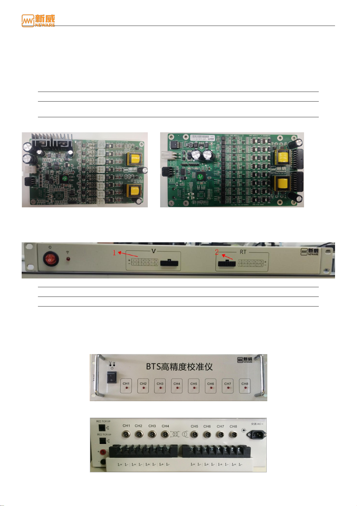
1 SMB-MOULE-1.1
The pull-up resistor and the pull-up port voltage are stable
2 SMB-MOULE-1.3
The pull-up resistor and the pull-up port voltage have four gears each, which can
be configured on the client.
The following figure shows the front view of different versions of SMBUS boards
Figure 2-5 SMB-MOULE-1.1 module Figure 2-6 SMB-MOULE-1.3 module
2.4. AUX5
AUX5 series of auxiliary machine are connected with the mid-machine, accept the control of the mid-machine. With the
lower-machine, they also perform real-time sampling of battery voltage and temperature.
Figure 2-7AUX5 Front view
1 Voltage socket
For connection of voltage test cable
2 Temperature socket
For connection of temperature test cable
2.5. CALI5
The automatic calibration tool CALI5 is connected to the server, the mid-machine, and the multi-meter to operate the
calibration of the channel to eliminate the inherent error of the device, i.e., eliminate the system deviation of the control
value and the sampling value of the system deviation. Before the battery test equipment is manufactured or after a
calibration cycle, it is necessary to use the calibration tool CALI5 for channel calibration.
Figure 2-8 CALI5 Front panel
Auto-calibration machine CALI5 back panel Figure 2-9:
Figure 2-9 CALI5 back panel

BTS User Manual
14 /94
Neware Technology Ltd.
http://www.newarebattery.com
2.6. Connection of Test Equipment
This section describes how to connect the tester. The following uses the BTS9008 as an example:
1. Power connection
This device uses a three-core power cord to connect to the power socket of the mid-machine and then to the grid.
Attention: Please note that the input voltage. Grounding terminal is effectively grounded!
2. Mid-machine connection
The mid-machine is connected to the BTS9.1 upper-machine through TCP/IP port.
Attention: Pay attention to fire prevention and keep away from flammable objects.
3. Aux connection
The aux is connected internally with the mid-machine to realize communication without external connection.
4. Battery connection
When connecting the battery, the current/voltage cable and communication cable of the battery have a strict
corresponding relationship with the cable sequence on the channel interface. Please check the cable sequence of the
channel interface carefully when connecting the device as shown in the figure below).
V+:Cathode Voltage V-:Anode Voltage I+:Cathode Current I-:Anode Current C:SCL clock line D:SDA data cable
Figure 2-10 Channel wire connection
Warning: When connecting the battery to the clamps, ensure that the cathode and anode of the
battery are correctly connected to the positive and negative terminals of the clamps to prevent
accidents during the test.

BTS User Manual
15 /94
Neware Technology Ltd.
http://www.newarebattery.com
Chapter 3 Installation and Maintenance
This chapter introduces the installation and maintenance of the system from three aspects: software installation, hardware
maintenance, and software uninstall.
3.1. Installation
PC software installation is assigned to new installation and upgrade installations. The new installation is for the user's
first-time installation. Upgrade Installation: This feature enables users to upgrade existing software.
New Installation
When you install the host software for the first time, you can choose default installation or a personalized installation.
Default installation: Do not select the corresponding software module. Follow the default options on the installation page
and install the software as prompted.
Personalized installation: Users can install clients, servers, backup servers, and reporting servers based on different
requirements. You can manually set an installation path and select the language.
Notice: The software only supports NTFS file systems. Before installation, disable the Windows firewall or
enable ports TCP8002, 8003 (device ports), and 8004.
Figure 3-1 Hard disk file system display window
1. The operating environment of the client and server is as follows: Form 2: Server Operating Environment
Form 2 Operation requirement of server
Components
Parameters
CPU
>Core Dual-core or Q9550(4 core)
Frequency
>2.4GHz
RAM
>4GB
Hard-drive
SATA socket, >500GB(with 3 units of hard-drive RAID5(recommended))
File form
NTFS
Operation system
Microsoft Windows 7/ 8/10/11 64 bit
Port
Ethernet communication port, RS232/485
Switch
Switch will be needed for multi machines.
Power source
UPS recommended
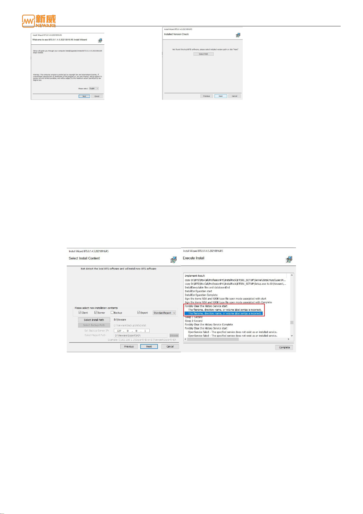
2. Operation software installation
Decompress the BTS.9.1.4 file, open the decompressed BTS91_SETUP file, and run Setup.exe as the administrator to
go to the installation wizard page, as shown in Figure 3-2. User can select the Chinese or English version as required.
Click Next button to enter BTS9.1.4 installation interface, as figure 3 - 3 shown:
BTS User Manual
16 /94
Neware Technology Ltd.
http://www.newarebattery.com
Figure 3-2 Installation guide Figure 3-3 Software version check
If you select "Manually specify the installed version directory," you can select a previous software installation directory to
overwrite the installation.
If you click Next, the Select Installation Content page is displayed. The installation wizard directly locates the directory
that was installed before, but this directory must be empty before the next installation can be performed. You can click the
"Select installation path" button to select a new installation directory.
The default installation are includes client installation and server installation. You can also select the installation contents as
required. Click the Next button to start the software installation after confirming precautions such as disabling the firewall,
as shown in Figure 3-4.
During the installation, if OpenService Failed is displayed during the process of forcibly clearing historical services, it is
because the user installs the software for the first time and the system does not have historical services to be cleared. This
will not affect the installation and operation of the software and will not be displayed when the software is installed again,
as shown in Figure 3-5:
Figure 3-4 Select Content Figure 3-5 Installation
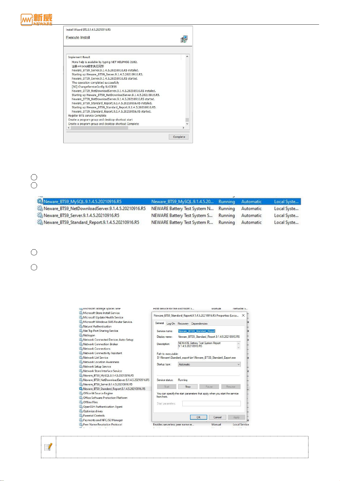
If the installation is complete, click the Complete button to exit the installation guide, as figure 3-6 shown:
BTS User Manual
17 /94
Neware Technology Ltd.
http://www.newarebattery.com
Figure 3-6 Installation complete
3. Complete the software installation
If you select "Install Server" and "Install Backup Service" during personalized installation, check whether the options
are correctly installed after the installation:
1Open“Control panel”→“Managing tools”interface.
2As shown in Figure 3-7, select service to view Neware_BTS9_MySQL, Neware_BTS9_Server, and Newa
re_BTS9_Backup.The four services are listed on the right and have already begun.
Figure 3-7 Server display window
If all functions are installed, ensure that the five services are started. If any service is not started, right-click
the service and choose Start from the shortcut menu.
3If any of the five services is missing from the list, uninstall the latest installed services and reinstall them. Then
check whether the server is correctly installed (repeat the above steps).
4If the any of the five services is manual, practice the following steps to change the startup type to automatic. The
Neware_BTS9_Standard_Report service, whose startup type is manual, is used as an example.
Methods:
Right-click“Neware_BTS9_Standard_Report”→Right-click Properties, and the Properties dialog box is
displayed.
Select Automatic from the drop-down list box. As shown in the figure below:
Figure 3-8 Neware_BTS9_ Standard_ReportService Properties dialog box
Notice: In the computer management window, right-click and choose "Stop" from the shortcut
menu to stop the running service. This operation is required to shut down the running service
when the server needs to be manually upgraded.

BTS User Manual
18 /94
Neware Technology Ltd.
http://www.newarebattery.com
Upgrade
If the user has installed the elder version of BTS9 operation software, this software can be upgraded directly when
compatible with the new version without uninstalling the current software. If they are incompatible, uninstall them first and
then install the new version.
The upgrade process as follow:
1. See Step 1 in the software installation process.
2. Select an installation language and click Next. The Installed Version Check interface will displayed. Information about
the installed software version and installation directory is displayed on the interface. See Figure 3-9:
3. Click Next. On the Select Upgrade Content page, you can select the upgrade mode and upgrade content as required.
Upgrade mode By default, the client and server are upgraded in the original directory, as shown in Figure 3-10. Click
Next to confirm the warning content and enter the software upgrade interface.
Figure 3-9 Version check Figure 3-10 Selection of upgrade content
Figure 3-11 Notice of Upgrade
Confirm information:
Before you upgrade the server, please confirm:
All channels connected to this server have been stopped. If there are any channel are operating, stop or pause
the test first.
Equipment has been stopped for more than 20 minutes.
Before you upgrade the server, please confirm:
All client-related software has been closed: BTSDA, BuildTest, and Neware_BTS9_Client.
Client files, such as log files, that are opened by other software have been closed.
Before you upgrade the server, please confirm:
All back-up software has been closed: Neware_BTS9_Backup.
Backup files, such as log files, that are opened by other software have been closed.
4. Click OK to exit the installation guide, and the software will be successfully upgraded.
3.2. Hardware Maintenance
If you need to add other hardware devices or have a device connection problem, you can use the hardware maintenance
method described in this section to find and resolve this problem.
BTS User Manual
19 /94
Neware Technology Ltd.
http://www.newarebattery.com
First, after the hardware is connected, use the client search function to search for the
device and ensure that the IP address is correct. Ensure that the first three segments of the IP address are the same and that
the last segment is different. Then, connect the TCP/UDP debugging tool to the corresponding device to perform debugging.
The specific operation process is as follows:
1. Hardware connection
Method of connecting the device as described in Section 2.6. After the device is connected, check the circuit, turn the
power on and start the device, and ensure the device indicator is on.
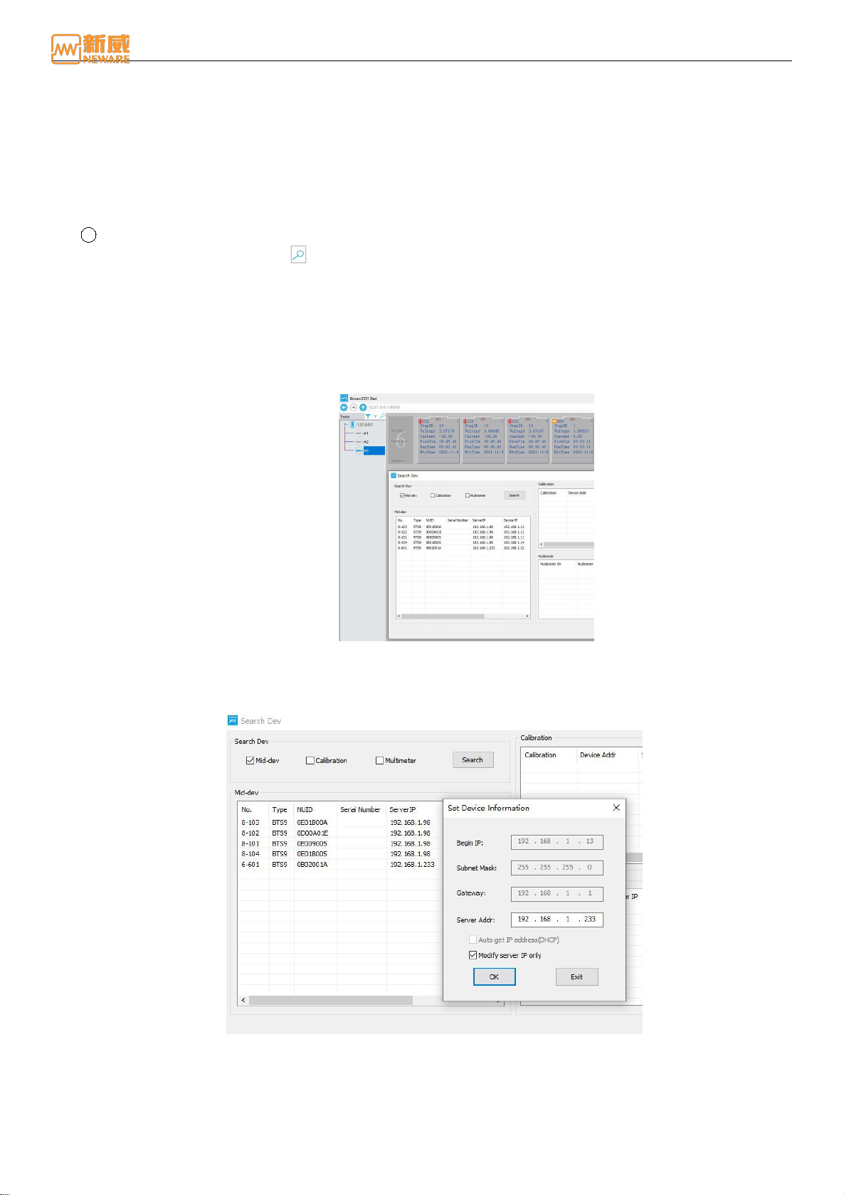
2. Equipment searching
1Searching for devices from BTS software
Click device search button on BTS device list display area, the search dialog box will be displayed.
You can select Mid-machine, Calibrate Tooling, and Multi-meter as required. Click the Search button to
display all online devices and related device information in the list.
Double-click the device list. The Set Device Information dialog box is displayed. You can change the MAC
address as required. Select the Automatically Obtain IP Address (DHCP) option box to automatically obtain
an IP address. As shown in the picture below, click the OK button to complete the modification.
The device IP address in the device information is the IP address of the mid-machine. The server's IP address
must be the same as the IP address of the PC.
Figure 3-12 Equipment searching interface
Inside the BTS9000 high precision tester, every 8-channel are corresponding to a mid-machine. When searching for the
mid-machine through the client, the mid-machine with the same channels number and the same code will be found, as
shown in the figure below, multiple BTS9 devices on the mid-machine have been searched.
Figure 3-13 Equipment searching interface
When using these devices, you need to change the server IP addresses of these channels to the IP addresses of the
current PC. After the modification, the four channels of the device will be activated. The client will map all these
device channels to the same mid-machine in the form of multiple channels of the mid-machine, as shown in the
following figure:
Table of contents
Other Neware Test Equipment manuals


Popular Test Equipment manuals by other brands


Hanna Instruments
Hanna Instruments HI 96724C instruction manual

Fluke
Fluke T5-600 user manual

DRUCK & TEMPERATUR Leitenberger
DRUCK & TEMPERATUR Leitenberger LR-Cal LPC 300 operating manual

axing
axing BZU 10-00 Operation instructions

Tektronix
Tektronix TSG 120 instruction manual

Cirris
Cirris CH2 Getting started guide


