NewLife BEST-X Series User manual

Manuale
Doc. HBI070-2
Manuale di Installazione e uso EVOSTYLE N.G.
Mod. MQI006-0
BEST-X LINE INSTALLATION AND USER MANUAL
Mod. MQI006-0 Doc. HBE220-1

MANUAL
Doc. HBE220-1
Installation and User Manual BEST-X-DC WITH
TIM-X
Mod. MQI006-0
INDEX
GENERAL ASPECTS ..........................................................................................................................1
Introduction ....................................................................................................................................... 1
Descriptions ....................................................................................................................................... 1
Technical data ....................................................................................................................................... 5
Other Data ....................................................................................................................................... 6
INSTALLATION AND USE...................................................................................................................6
Use Conditions ....................................................................................................................................... 6
General symbols ....................................................................................................................................... 7
Symbols for transportation and storage................................................................................................... 9
Information for installation ....................................................................................................................... 10
Utensils and tools required for installation (not supplied) ........................................................10
Electrical indications.....................................................................................................................10
Wiring and connection conductors sections ............................................................................10
Installation ..................................................................................................................................... 12
Instructions for installation in wall mode.....................................................................................12
Settings ...........................................................................................................................................24
Springs adjustment of the double pantograph arm ............................................................................ 25
Instructions for installation in column mode .......................................................................................... 26
Palmtop operation .......................................................................................................................32
Operation ..................................................................................................................................... 36
Matching Screen ..................................................................................................................................... 42
Display Options Screen ............................................................................................................................ 43
Calibration Screen.................................................................................................................................... 44
Functioning e time scale:......................................................................................................................... 45

MANUAL
Doc. HBE220-1
Installation and User Manual BEST-X-DC WITH
TIM-X
Mod. MQI006-0
The Monoblock Does Not Emit X-Rays .......................................................................................51
Procedures for the filament current measures:.........................................................................54
Measurement of the filament current........................................................................................54
Plates positioning ..........................................................................................................................57
Servicing of the x-ray unit.............................................................................................................62
Extraordinary maintenance.........................................................................................................63
Thermal Curves ..................................................................................................................................... 69
Emission and filament characteristics .................................................................................................... 69
Safety aspects ..................................................................................................................................... 70
Possible drawbacks found in the radiographs results .......................................................................... 71
Clear image ..................................................................................................................................... 71
Recommendations .......................................................................................................................72

Manual
Doc. HBE220-1
Installation and User Manual BEST-X-DC WITH
TIM-X
Mod. MQI006-0
NEW LIFE RADIOLOGY S.R.L. Corso Allamano 13/15 interno G 10095 Grugliasco (TO)
Italy phone and fax + 39.011. 781994 info@newliferadiology.it
www.newliferadiology.it
1
GENERAL ASPECTS
Introduction
Dear Customer,
Thank you for the preference granted to our product. We invite you to attentively read the
present instructions that will help you to get the maximum of your X-ray diagnostic
information with minimal x-ray use.
This manual has the purpose to provide the User with instructions for proper, safe and
efficient operation.
The equipment must be used in accordance with the procedures contained in the manual
and never for purposes other than those specified herein.
The User is responsible for what concern the fulfilments in legal matters facing installation
and equipment functioning.
The plant can only be used by medical personnel in possession of the related licenses
enablers and aware of the risks associated with the use of ionizing radiation sources. The use
of X-ray sources for purpose of medical diagnostics is subject to specific authorizations
and/or communications to the Authorities responsible for vigilance. The User is responsible
for the use unauthorized of the plant. The User of the X-ray plant for dental complementary
radiology is also required, without exception, to observe the regulations governing the
safety of exposure to ionized radiations sources for workers, for member of the public, for
population and patients.
If the equipment is not operated correctly or it is not made proper maintenance, the
manufacturer can not be held responsible for any breakages, lesions and mal functioning.
Descriptions
“CAUTION: Do not modify this equipment without the manufacturer’s permission.”
BEST-X-DC radiological unit is an equipment designed to obtain intraoral dental radiographs
arranged to be used with acquisition systems (conventional films, phosphor plates and
videoradiografie).
According to Directive 2007/47/CE (Legislative Decree 37/2010) it is classified in CLASS IIb.

Manual
Doc. HBE220-1
Installation and User Manual BEST-X-DC WITH
TIM-X
Mod. MQI006-0
NEW LIFE RADIOLOGY S.R.L. Corso Allamano 13/15 interno G 10095 Grugliasco (TO)
Italy phone and fax + 39.011. 781994 info@newliferadiology.it
www.newliferadiology.it
2
The unit is manufactured in accordance with the actual international standards on the
protection of ionizing radiation, electrical safety, mechanical safety and electromagnetic
compatibility for electromedical equipment.
The equipment consists of the following parts:
Monoblock
BEST-X-DC Monobloc require the use of X-
ray tubes CEI OX/70-3
BEST-X-DC complies with EU directives on
electromagnetic compatibility.
However, it may be appropriate to avoid
installing the equipment in the immediate
vicinity of other electrical equipment with
which they could generate
electromagnetic fields of mutual
disturbance. It is also important to avoid
using electrical appliances (eg.
electrosurgery, cell phones, etc…) in the
immediate vicinity of the apparatus during
its use.
Articulated support double pantograph with wall support or mobile
The monoblock is directed within the
installation area by an articulated arm
double pantograph; this arm, coupled to the
wall support through an extension cable of
variable size (mm 400-800-1100), has a
maximum extension which varies between
1730 mm and 2430, depending on the
extension cord used.

Manual
Doc. HBE220-1
Installation and User Manual BEST-X-DC WITH
TIM-X
Mod. MQI006-0
NEW LIFE RADIOLOGY S.R.L. Corso Allamano 13/15 interno G 10095 Grugliasco (TO)
Italy phone and fax + 39.011. 781994 info@newliferadiology.it
www.newliferadiology.it
3
Palmtop
Palmtop of the BEST-X-DC allows
managing the exposure times and
adjustment of kV(60/70) and mA (4/7) and
at the same time it guarantees maximum
safety in the use of X-ray tubes for
electromedical purposes for intraoral
diagnostic;
The management of the palmtop occurs
through the use of the RF radio control;
The control panel of the palmtop is
provided with touchscreen display so as to
facilitate its use;
The functioning of the palmtop is
managed by RF radio control to vigilant
device better known as dead man’s
device, in such a way as to guarantee
maximum safety for both, the operator
and the patient;
The palmtop does not permit use in the X-
ray scopy;
The time scale set by the values of the
factory complies with scale R10 relative to
the standard EN60601-2-7 (IEC 60601-2-7);
The exposure times shown on the display of
the timer are expressed in ms.
The maximum time that can be set is 1 s
(the display will read 1000) while the
minimum time is 20 ms. (the display will
read 0020);

Manual
Doc. HBE220-1
Installation and User Manual BEST-X-DC WITH
TIM-X
Mod. MQI006-0
NEW LIFE RADIOLOGY S.R.L. Corso Allamano 13/15 interno G 10095 Grugliasco (TO)
Italy phone and fax + 39.011. 781994 info@newliferadiology.it
www.newliferadiology.it
4
BEST-X-DC has a unique safety system against short circuits or malfunction of the unit, this
system is the automatic fuse THERMOSWITCH.
This device intervenes in case of conduction for a time longer than 6 sec. In this situation
it blocks the continuity between the control unit and the monoblock, thus preventing the
emission of anomalous X-ray.
In case of intervention of the THERMOSWITCH, this will be replaced, this operation requires
a service call to technical assistance.
Drawings, schematics, components lists, instructions for repairs:
New Life Radiology is committed to providing, upon request, drawings, circuit diagrams,
component parts lists, instructions, or other information that can serve for qualified technical
personnel, to perform the repair of any parts that can be repaired.
The Manufacturer reserves the right to make changes at any time without notice.

Manual
Doc. HBE220-1
Installation and User Manual BEST-X-DC WITH
TIM-X
Mod. MQI006-0
NEW LIFE RADIOLOGY S.R.L. Corso Allamano 13/15 interno G 10095 Grugliasco (TO)
Italy phone and fax + 39.011. 781994 info@newliferadiology.it
www.newliferadiology.it
5
Technical data
Classification:
Electro medical equipment of Class I
With part applied type B
Head:
Monoblock with potential constant 100KHz
model CEI OX/70-3
Type:
60-70 kVpselectable (±5%)
Feeding voltage:
230 V~ (50 Hz) monophase
Maximun Power absorbed from the net:
0,800 KW
Cone diameter:
60 mm
Max symmetrical rays field:
Ø60 mm to SSD 200 mm
Anodic current:
4 mA –6.5 mA selectable
Anodic voltage:
60, 70 kV selectable
Emission time:
from 20 mS to 1000 mS scale R10
Exposition time:
predefined
Max anodic voltage:
70 kV
Reference current time:
7mAs to 70 kV, 7mA, 1 s
Max supplied power:
0,49 kW a 70 kV, 7mA
Maximum apparent resistance of the power supply:
0.44
Weight:
Wall model
Mobile model
27 kg
40 kg
Accuracy Load Factors
Voltage accuracy
± 5 %
Current accuracy
± 3 %
Time accuracy
± 5 %
Dose accuracy
± 5 %

Manual
Doc. HBE220-1
Installation and User Manual BEST-X-DC WITH
TIM-X
Mod. MQI006-0
NEW LIFE RADIOLOGY S.R.L. Corso Allamano 13/15 interno G 10095 Grugliasco (TO)
Italy phone and fax + 39.011. 781994 info@newliferadiology.it
www.newliferadiology.it
6
Other Data
Maximum current automatic switches for the feeding
net
Magnetic thermal switch from 10 A (CEI
23-3)
High voltage measure method:
Not invasive method
Current measure method in the radiogenic pipe:
See page 54
Charge application time determination method:
Not invasive method
Interposition aluminium filter between rays window and
cone collimator:
Al 1 mm (AIP99,9 UNI3567)
INSTALLATION AND USE
Use Conditions
The equipment is designed for continuous operation with intermittent charge.
The operating times are with intermittent charge with a duty cycle of 1.30 (for each
working period will correspond to 30 pause)
Classification according to Directive 2007/47 / EC
(Legislative Decree no. 37/2010)
Class IIb
Protection against electrical dangers:
Class I
Protection degree against the direct and indirect
contacts:
Equipment with parts applied type B
Protection degree against water penetration:
Common equipment IPX0
Use safety degree in presence of inflammable
anaesthetic mixture:
Equipment not suitable to an use in
presence of an inflammable anaesthetic
mixture with air or with oxygen or with
nitrogen protoxide
Use conditions:
Equipment for continuous operation with
intermittent charge
Installation:
Permanent e mobile

Manual
Doc. HBE220-1
Installation and User Manual BEST-X-DC WITH
TIM-X
Mod. MQI006-0
NEW LIFE RADIOLOGY S.R.L. Corso Allamano 13/15 interno G 10095 Grugliasco (TO)
Italy phone and fax + 39.011. 781994 info@newliferadiology.it
www.newliferadiology.it
7
General symbols
Caution: consult annexed documentation
Ionizing radiation
Apparatus with Type B part applied
Earth protection
O Switch open(disconnected from mains supply)
I Switch close(connected to mains supply)
Red point, placed on the cover of the unit, indicate focal spot
Alternating current
Radiation emission symbol
Follow annex instructions
Symbol in conformity with European Directive 2002/96/Ec (Weee).

Manual
Doc. HBE220-1
Installation and User Manual BEST-X-DC WITH
TIM-X
Mod. MQI006-0
NEW LIFE RADIOLOGY S.R.L. Corso Allamano 13/15 interno G 10095 Grugliasco (TO)
Italy phone and fax + 39.011. 781994 info@newliferadiology.it
www.newliferadiology.it
8
Manufacturer
Symbol in conformity with Community Legislation. The symbol is followed by a
number which identifies the notified organism which certifies and monitors
such compliance
REF Product Code
SN Equipment Serial Number. To be used for all communication with
manufacturer / service technician
TUBE X-ray Tube Serial number

Manual
Doc. HBE220-1
Installation and User Manual BEST-X-DC WITH
TIM-X
Mod. MQI006-0
NEW LIFE RADIOLOGY S.R.L. Corso Allamano 13/15 interno G 10095 Grugliasco (TO)
Italy phone and fax + 39.011. 781994 info@newliferadiology.it
www.newliferadiology.it
9
Symbols for transportation and storage
27 kg

Manual
Doc. HBE220-1
Installation and User Manual BEST-X-DC WITH
TIM-X
Mod. MQI006-0
NEW LIFE RADIOLOGY S.R.L. Corso Allamano 13/15 interno G 10095 Grugliasco (TO)
Italy phone and fax + 39.011. 781994 info@newliferadiology.it
www.newliferadiology.it
10
Information for installation
PLASTIC MATERIAL PLUGS NOT ALLOWED
Utensils and tools required for installation (not supplied)
1 multi meter
1 meter
1 fixed key from 13 mm
1 nandle spanner from 5,5 mm
1 set of Allen spanner
1 spirit level
1 plastic mallet
1 percussion drill with points from Ø 3 to Ø 13 mm
1 thin screwdriver for electrical connection
1 medium screwdriver
1 net feeding cable with three wires (2 conductors + 1 ground) of section 1,5 mmq for
a reduced length of not over 40 m (for superior lengths use the section cable
corresponding to that indicated from the Country actual standards).
Electrical indications
All works for the feeding electric plant must be performed in conformance with the actual
reference standards for plants and locals for medical use. (CEI 64-8-710).
A feeding of 230 V~to 50 Hz. is required. For the phase conductors, neutral and ground, the
minimum section must be of 1,5 mmq of copper. It recalls the necessity to perform the
ground connection as required by current legislation.
The plant must be performed and tested by qualified personnel.
The warranty excludes damages caused by erroneous connection.
Wiring and connection conductors sections
A three conductors cable (3x1,5 mmq) is expected between the net switch and the
equipment. For the assembled versions and in all cases of separate installation from the
control unit, a second cable, always 3 x 1.5 sq mm, shall be provided between the control
unit and the support. Please note that the radiological groups are supplied without a plug

Manual
Doc. HBE220-1
Installation and User Manual BEST-X-DC WITH
TIM-X
Mod. MQI006-0
NEW LIFE RADIOLOGY S.R.L. Corso Allamano 13/15 interno G 10095 Grugliasco (TO)
Italy phone and fax + 39.011. 781994 info@newliferadiology.it
www.newliferadiology.it
11
for leaving the buyer free to connect to equipment already on site.
Efficient grounding is a first necessary condition for the proper functioning of the system,
respecting the symbols indicated for connection:
.
F –Line (brown) N –Neutral (blue) T –Ground (yellow-green)
Point A grounded power cord; Point B output external lamp
Check carefully all connection cables, plugs and line contacts.
Remember that the suppliers must support a current of at least 10A.
The connection to the external lamps must be done by connecting the output LAMP
indicated with the letter A in the figure above. The lamp must be of value 30W 230-240 Vac.

Manual
Doc. HBE220-1
Installation and User Manual BEST-X-DC WITH
TIM-X
Mod. MQI006-0
NEW LIFE RADIOLOGY S.R.L. Corso Allamano 13/15 interno G 10095 Grugliasco (TO)
Italy phone and fax + 39.011. 781994 info@newliferadiology.it
www.newliferadiology.it
12
according to the actual reference standard for plants and locals for medical use (IEC 64-8-
710).
Installation
“CAUTION: To avoid the risk of any electric shock, this device must be connected only to
power mains gifted with ground protection.”
The installation is provided in both wall and mobile version on column.
Instructions for installation in wall mode
The system in wall version consists of the components shown in the following legend:
A wall plate
B extension
C double pantograph arm
D palmtop
E monoblock

Manual
Doc. HBE220-1
Installation and User Manual BEST-X-DC WITH
TIM-X
Mod. MQI006-0
NEW LIFE RADIOLOGY S.R.L. Corso Allamano 13/15 interno G 10095 Grugliasco (TO)
Italy phone and fax + 39.011. 781994 info@newliferadiology.it
www.newliferadiology.it
13
Quotas with relative useful space –EXTENSION FROM mm 400

Manual
Doc. HBE220-1
Installation and User Manual BEST-X-DC WITH
TIM-X
Mod. MQI006-0
NEW LIFE RADIOLOGY S.R.L. Corso Allamano 13/15 interno G 10095 Grugliasco (TO)
Italy phone and fax + 39.011. 781994 info@newliferadiology.it
www.newliferadiology.it
14
Quotas with relative useful space –EXTENSION FROM mm 800

Manual
Doc. HBE220-1
Installation and User Manual BEST-X-DC WITH
TIM-X
Mod. MQI006-0
NEW LIFE RADIOLOGY S.R.L. Corso Allamano 13/15 interno G 10095 Grugliasco (TO)
Italy phone and fax + 39.011. 781994 info@newliferadiology.it
www.newliferadiology.it
15
Quotas with relative useful space –EXTENSION FROM mm 1100

Manual
Doc. HBE220-1
Installation and User Manual BEST-X-DC WITH
TIM-X
Mod. MQI006-0
NEW LIFE RADIOLOGY S.R.L. Corso Allamano 13/15 interno G 10095 Grugliasco (TO)
Italy phone and fax + 39.011. 781994 info@newliferadiology.it
www.newliferadiology.it
16
Wall plate installation
This equipment is supplied with a plate for mural fixing (A), closed by a plastic cover
(fig.1). Remove the plastic cover.
fig. 1 fig. 2
Define the position on the wall of the WALL PLATE (A) with respect to the amplitude
of the working field chosen and to the size of the structure that the same can assume
right or left of the axis of the wall plate when it is inactive.
Plot on the wall the position of the six holes making sure to check the perpendicularity
with a plumb line. If the electric plant is recessed, track also the corresponding hole
(Fig. 2)
Drill six holes on the wall starting with the tip of 7, enlarging gradually. This to not
demolish the stability and maintain under control the interaxes. For walls of full or
holed or cement bricks use metallic plugs preferable of 12 equipped with
unmissable female grain and separated screw 6 with hexagonal head and washer.
For types of wall of insufficient reliability it is necessary to resort to the construction of a
reinforcement to be defined case by case.
Apply the wall plate and bring it closer parallel to the wall by tightening the 6 screws
alternately, if the wall is not perfectly flat put adequate thicknesses so as not to
deform the wall plate.

Manual
Doc. HBE220-1
Installation and User Manual BEST-X-DC WITH
TIM-X
Mod. MQI006-0
NEW LIFE RADIOLOGY S.R.L. Corso Allamano 13/15 interno G 10095 Grugliasco (TO)
Italy phone and fax + 39.011. 781994 info@newliferadiology.it
www.newliferadiology.it
17
Extension installation
Extract the SEGER from the extension (B), and enter it in the wall plate (A), as shown
in fig. 3
fig. 3
This manual suits for next models
3
Table of contents
Other NewLife Medical Equipment manuals
Popular Medical Equipment manuals by other brands
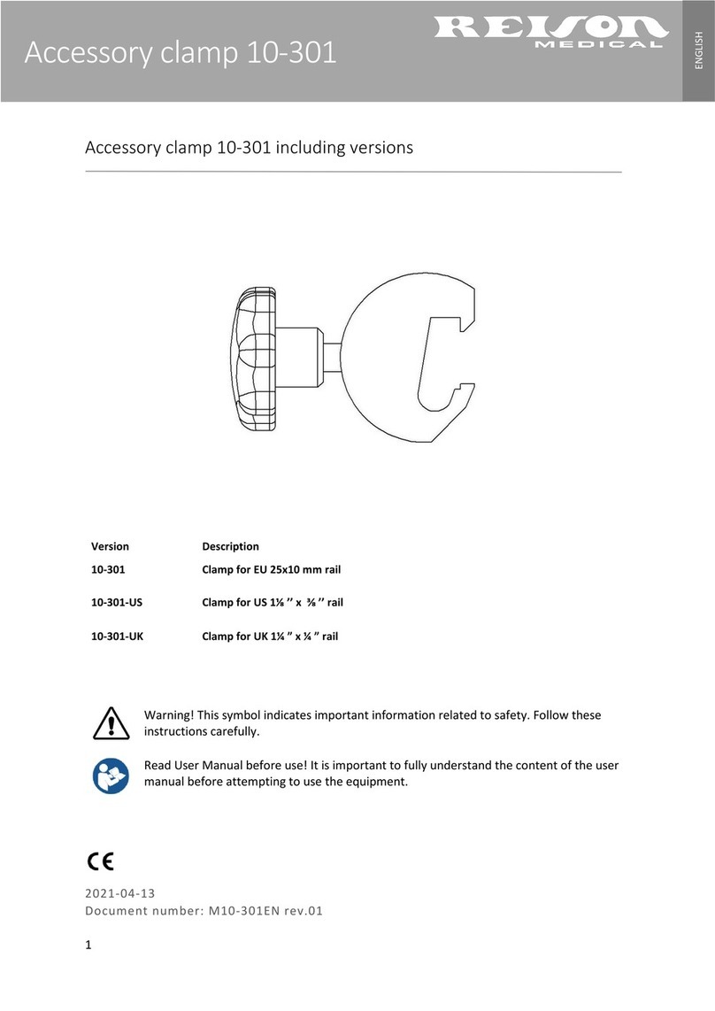
Reison
Reison 10-301 user manual
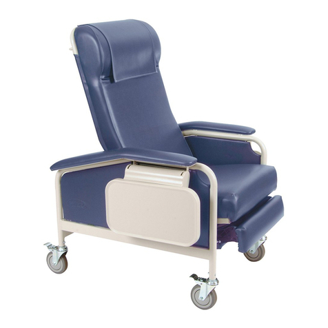
Winco
Winco 6530 Owner's operating and maintenance manual

Gima
Gima OXY-PED Use and maintenance book

FIOR & GENTZ
FIOR & GENTZ NEURO CLASSIC Instructions for use
Instrumentarium
Instrumentarium ORTHOPANTOMOGRAPH OP300 quick guide
Bedfont
Bedfont GastroCH4ECK Gastrolyzer user manual
