newmotion Home Advanced 2.1 User manual


2Installation manual – NewMotion Home Advanced 2.1 / 2.2 - 071NMEN13
Table of content
1. Preface 3
1.1. Original instructions 3
1.2. Copyright 3
1.3. Disclaimer of liability 3
1.4. About this document 3
1.5. Used symbols in this document 3
1.6. Used abbreviations / terminology in this document 3
2. Safety 5
2.1. Introduction 5
2.2. Intended use and reasonably foreseeable misuse 5
2.3. Qualication of installer 5
2.4. Protective measures 5
2.4.1. Personal protective equipment (PPE) 5
2.5. Residual risks 6
2.6. How to handle in case of an emergency 6
2.7. Safety precautions 6
2.7.1. Electricity 6
2.8. Labels 6
3. Description of the product 7
3.1. Main parts 7
3.2. Internal connections 7
3.2.1. Internal connections for tethered cable 8
3.3. Technical specications 8
3.4. Nameplate / markings 10
4. Transport and storage 10
4.1. Transport 10
4.2. Storage 10
5. Installation 11
5.1. Scope of delivery/Check the contents 11
5.1.1. Home Advanced 2.1 / 2.2 11
5.1.2. Optional 11
5.2. Installation materials (not provided) 12
5.2.1. Power cable 12
5.2.2. Data cable (optional) 12
5.2.3. Earthing 12
5.2.4. Required nominal input voltage at charge point 12
5.2.5. Electrical protection 12
5.2.6. Charge point mounting 13
5.2.7. Installation tools and materials 13
5.3. Preparation 15
5.4. Mounting 16
5.4.1. Wall mount 16
5.4.2. Pavement mount 19
5.4.3. Soil mount 21
5.5. Electrical connection 24
5.5.1. Power cable 24
5.5.2. Tethered charging cable 25
5.6. Wired network connection (optional) 27
5.7. Installation DPM module (optional) 28
5.7.1. Installing the DPM for Business module 28
5.7.2. Connecting the charge point to the DPM module 30
5.7.3. Connecting the charge point to a smart meter 31
5.8. Finishing installation 32
6. Commissioning 34
6.1. Activating the product 34
6.2. Checks before commissioning 34
6.3. Switching on the product 34
6.4. Conguring the DPM module 35
6.5. Test charge point 35
6.6. Regular use 35
6.6.1. Start charging 35
6.6.2. Stop charging 35
6.6.3. Explanation of the LED colors 35
6.7. Tethered cable 35
7. Troubleshooting 36
8. Maintenance 40
8.1. Cleaning and sanitizing 40
8.1. Periodic maintenance 40
9. Disposal 40
Appendix A - EC Declaration of Conformity 41
Appendix B - EC Declaration of Conformity - Cable 42
EN
3Installation manual – NewMotion Home Advanced 2.1 / 2.2 - 071NMEN13
1. Preface
1.1. Original instructions
This manual has been translated into multiple languages. The original manual is written in UK English. All other language
versions are translations of the original manual.
1.2. Copyright
The content of this manual is protected by copyright and other intellectual property laws. The content of this manual
may only be copied, modied, reproduced, translated with express written permission from The NewMotion B.V. This
manual may only be published, transmitted, displayed or made available to a third party with express written permission
from The NewMotion B.V.
1.3. Disclaimer of liability
This manual is created for you with care.
We, however, do not guarantee that all information is complete, accurate and correct. Please check our website https://
newmotion.com for the latest version of this manual. Our product must be installed by certied professionals. How our
product should be installed and used depends on local circumstances and local and national regulation, which are not
mentioned in our manual. NewMotion is not responsible for any loss or damage whatsoever caused – including without
limitation, any indirect, personal or consequential loss or damage - arising from or in connection with the use of this
manual. Nor does NewMotion accept any liability for any such loss or damage arising out of your reliance on any
information contained in this manual. The manufacturer reserves the right to modify this manual without notication
beforehand. If you nd any unclarities or mistakes in this installation manual, or if you have any feedback or suggestions
document version in the subject.
1.4. About this document
This manual contains technical descriptions and instructions for the following product:
Category of product EVSE compatible with IEC 61851 Mode 3
Product name Home Advanced 2.1
Home Advanced 2.2
Home Advanced 2.1 Cable
Home Advanced 2.2 Cable
This manual contains all instructions and safety information for installation and commissioning of the product.
This manual is intended for the qualied technician that installs the product.
1.5. Used symbols in this document
This manual contains safety warnings that may result in injury when ignored. Each safety warning is indicated with a
signal word. The signal word corresponds with the level of risk of the described hazardous situation.
6WARNING Indicates that serious injury that may possibly lead to death can be sustained or that the product can
suffer serious damage if the instruction is not followed correctly.
6CAUTION Indicates that minor to moderate injuries may be sustained or that the product may suffer damage if the
instruction is not followed correctly.
NOTICE Indicates that there is additional emphasis on the instruction, without direct risk for injury or damages.
1.6. Used abbreviations / terminology in this document
AC supply Alternating current supply. Electrical device that supplies electric power to an electrical load, delivered
by alternating current
cm Centimeter
Consumer unit A distribution board designed for domestic installations
dBm Decibel
DC Direct current
EN
EN

4Installation manual – NewMotion Home Advanced 2.1 / 2.2 - 071NMEN13
DHCP Dynamic Host Conguration Protocol
DIN-rail A DIN rail is a metal rail of a standard type widely used for mounting circuit breakers and industrial
control equipment inside consumer units or distribution boards.
Distribution board A component of an electricity supply system that divides an electrical power feed into subsidiary
circuits, while providing a protective fuse or circuit breaker for each circuit in a common enclosure
(source: Wikipedia)
DPM Dynamic Power Management
(D)SMR (Dutch) Smart Meter Requirements
Electricity grid An interconnected network for delivering electricity from producers to consumers
EV Electric vehicle
EVSE Electric vehicle supply equipment
EV-Ready Born under the lead of automobile manufacturers Renault-Nissan EV-Ready mark is the result of a
technical quality work done at numerous workshops with representatives of the all the players in this
industry
GND Ground
GPRS General Packet Radio Service
H × W × D Height x Width x Depth
hPa The abbreviated name for hectopascal (100 x 1 pascal) pressure units which are exactly equal to millibar
pressure unit (mb or mbar)
IEC International Electrotechnical Commission
kg Kilogram
kW Kilowatt
LED Light-emitting diode
mA Milliampere
MCB Miniature circuit breaker. Can break a low voltage electrical circuit, in order to protect against
overloading or short-circuiting.
MID certified Measuring instruments directive certied. Required for energy meters that are used for billing purposes
mm Millimeter
NFC Near-eld-communication
Nm Newton meter
OCPP Open charge point protocol
PCB Printed circuit board
RCBO Residual cirquit breaker with overcurrent protection. Protects an electrical installation against both
excessive leakage currents and overcurrents caused by overloading or short-circuiting.
RCD Residual current device. Monitors an electrical installation to detect any leaking current caused by
overloading or short-circuiting.
RFID Radio-frequency identication
TCP Transmission control protocol
UTP Unshielded twisted pair
VVolt
WWatt
ZE-Ready ZE Ready is a mark registered by Renault. You can nd all the information on the ASEFA and LCIE
websites
EN
5Installation manual – NewMotion Home Advanced 2.1 / 2.2 - 071NMEN13
2. Safety
2.1. Introduction
Observe the instructions in this manual before you start working with the product. If you fail to follow the instructions
from this manual you can put yourself and others in danger.
Always comply with the information, such as labels and the nameplate, attached directly to the product and keep the
information in a legible condition.
Always comply with any applicable laws and regulations that have not been accounted for in this manual.
2.2. Intended use and reasonably foreseeable misuse
Home Advanced 2.1 / 2.2 is a charge point intended for charging electrical vehicles compatible with IEC-61851 Mode 3
denition and requirements. Electrical vehicles and cables used with this charge point should always be undamaged
and in their original state.
The product must only be operated within its performance limits and under the permitted ambient conditions, see
chapter 3.3. Technical specications.
The following is considered foreseeable misuse:
• use of adaptors, conversion adaptors or extension sets for cables.
• use in an environment that varies from or exceeds the given environmental conditions.
• use that varies from or exceeds the given operating conditions.
• failure to comply with the instructions in this manual.
• failure to eliminate faults, malfunctions or defects of the product that impose safety risks.
• unauthorized removal or modication of parts or safety devices of the product.
• use of spare parts or accessories that have not been approved by the manufacturer.
• operation in a ammable and/or explosive environment.
2.3. Qualification of installer
Only authorised technicians are allowed to perform installation and maintenance of the product. They must possess the
following qualications:
• are familiar and abide by the safety instructions and sections of this manual related to installation of the product;
• are familiar with and abide by the applicable local, national and international laws and regulations;
• are able to recognize the possible dangers of the product and take the necessary measures to protect persons and
property.
2.4. Protective measures
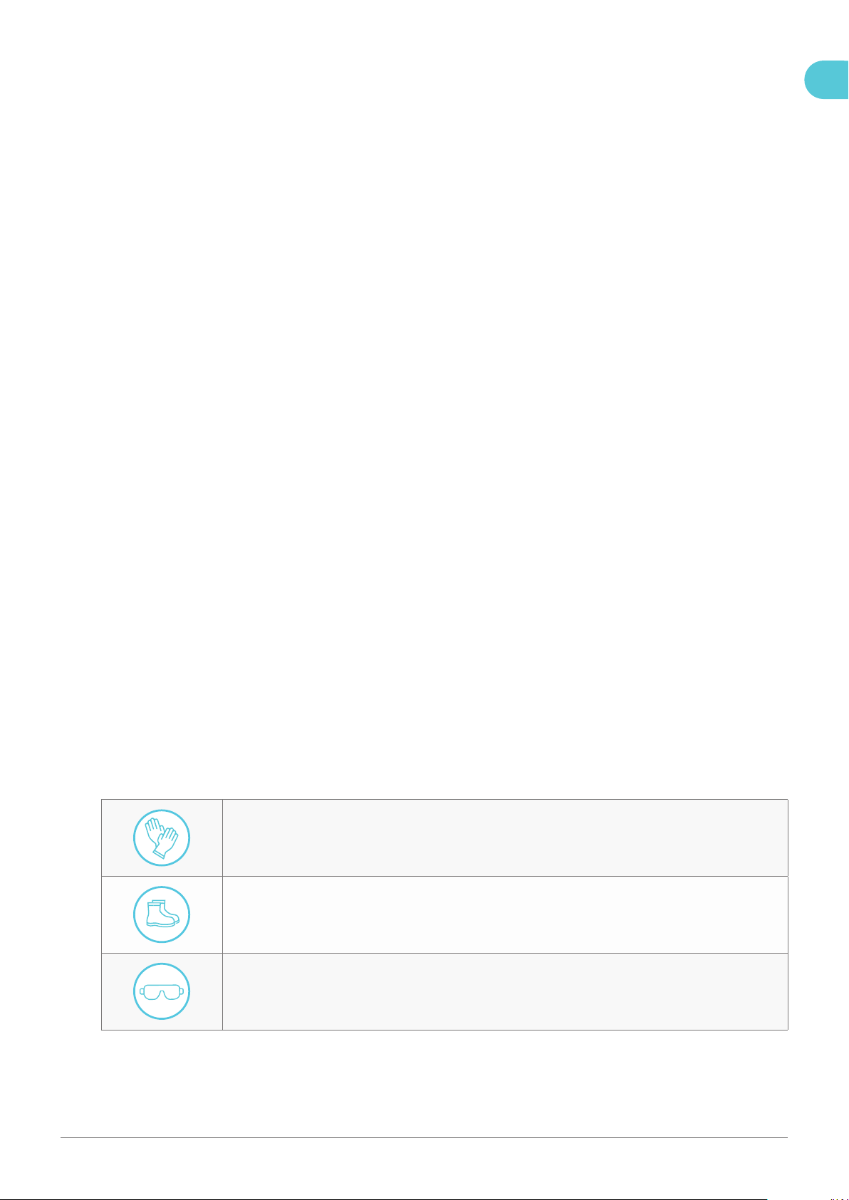
2.4.1. Personal protective equipment (PPE)
Wear insulating gloves while installing wires and electrical components to avoid damages from static
discharge.
Wear S3 class antistatic safety shoes.
Wear safety goggles/glasses while drilling holes to protect your eyes from dust or other particles that may
damage your eyes.
EN

6Installation manual – NewMotion Home Advanced 2.1 / 2.2 - 071NMEN13
2.5. Residual risks
Despite the safe design and construction of the product and the prescribed protective measures, the product
possesses residual risks. This manual provides safety messages to indicate these risks. The formatting and appearance
of safety messages that are dedicated to a particular section or sentence is explained in chapter 1. Preface. For the
overall safety messages see chapter 2.7. Safety precautions.
2.6. How to handle in case of an emergency
Immediately cut power to the circuit on which the charge point has been installed in case of an emergency.
2.7. Safety precautions
2.7.1. Electricity
6WARNING
- Always cut the power to the circuit before installing the product.
- The electrical system must be voltage-free during the entire installation procedure. Failing to do so can lead to
serious injury or even death.
- The installation procedure must be carried out by a trained electrician who works in accordance with all relevant
local laws and regulations.
- Do not install in potentially explosive atmospheres and/or zones with high electromagnetic radiation and/or in
ood-prone areas.
- The charge point is connected to the electricity grid and even if the equipment is switched off, hazardous
voltages may be present at the input terminals.
- Always switch off the AC supply before starting any work on the charge point and/or its installation. Do not carry
out any work in rainy conditions or when the humidity is above 95%.
- The safety guidelines are intended to ensure correct installation and usage. Any failure to comply with the valid
safety guidelines or instructions provided in this manual may result in re, electrocution or severe injury.
- The charge point is a product in safety class I and is supplied with an earth terminal for protection purposes.
- The AC input terminal blocks must be tted with an uninterruptible earth for protection purposes. Ensure that the
connection cables are tted with fuses and circuit breakers.
- Never replace a protection component with another type that decreases the safety level. First check the full
installation to determine if that component can be used with the existing installation components.
- Before you switch on the charge point, check that the available power source matches the conguration settings
of the product, as described in this manual.
- Tripping of the MCB, RCD or RCBO could be caused by an earth fault, leakage or a defect contactor. If, after
resetting the MCB, RCD or RCBO, the device cannot be activated or immediately trips again; please contact
NewMotion or your installer.
2.8. Labels
The warning labels and information signs on the product must be followed. The warning labels and information signs
must be kept legible and must be replaced if necessary. For this purpose, contact the manufacturer.
EN
7Installation manual – NewMotion Home Advanced 2.1 / 2.2 - 071NMEN13
3. Description of the product
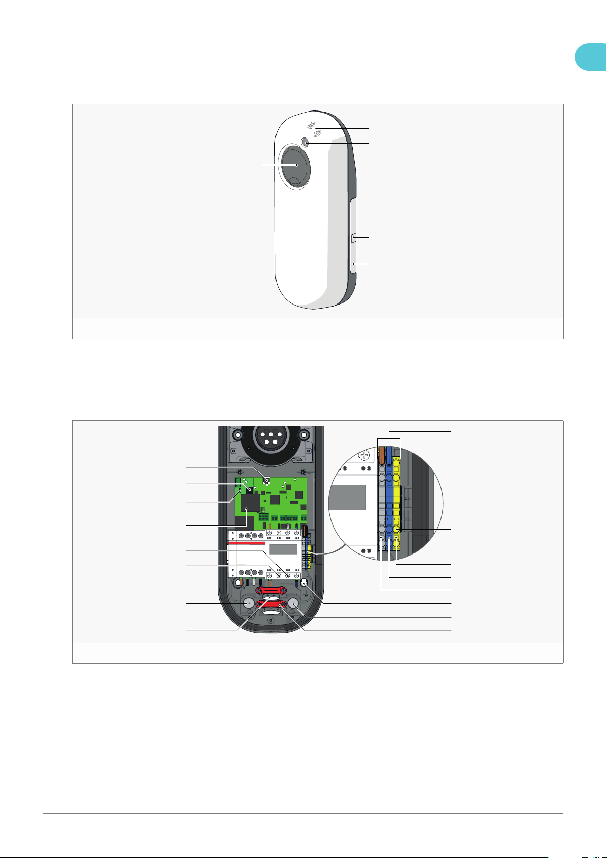
3.1. Main parts
1
2
5
3
4
1
1. RFID reader
2. LED status indicator
3. Identication label with serial number
4. Product details
5. Type 2 EV plug socket and cover lid, or dummy
socket for tethered cable
3.2. Internal connections
1
3
4
5
6
7
8
9
10
11
12
13
14
15
16
2
2
1. Terminal blocks
2. Earthing point for pole mount
3. Earth connection
4. Neutral connection
5. Phase 1 connection
6. Earthing pole
7. Data cable inlet with grey rubber rommet
8. Power cable clamps
9. Inlet for power cable
10. Data cable inlet with grey rubber rommet
11. Phase 2 connection
12. Phase 3 connection
13. DC fault detection module
14. Connection DC fault detection module
15. P1 port (DPM module)
16. Ethernet port
EN
8Installation manual – NewMotion Home Advanced 2.1 / 2.2 - 071NMEN13
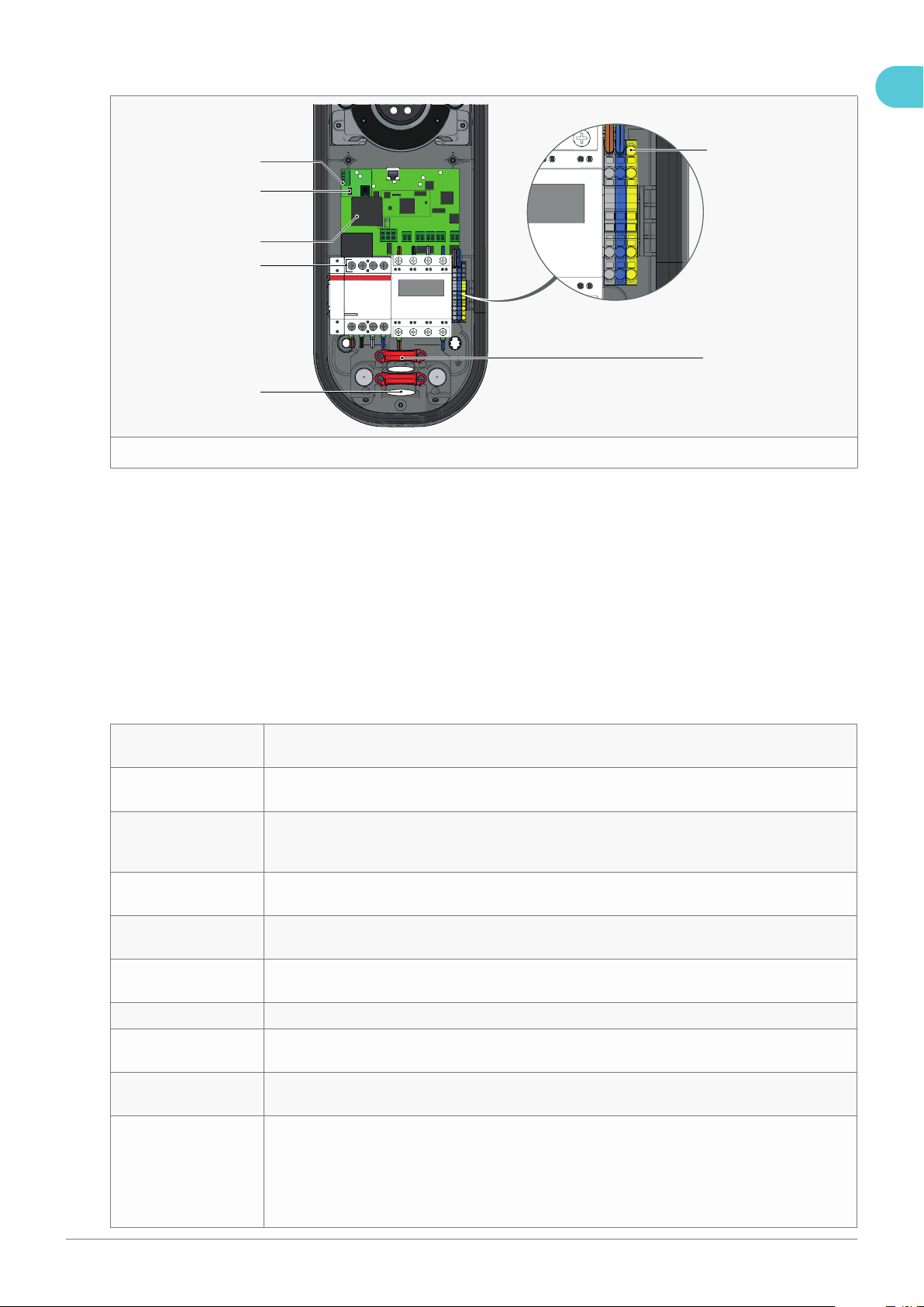
3.2.1. Internal connections for tethered cable
2
3
4
6
7
5
1
3
1. Earthing tethered cable
2. Cable clamp
3. Tethered cable inlet
4. Tethered cable connection. Keep the same
order as the connection under contactor
L1 = portal 1
L2 = portal 2
L3 = portal 5
Neutral = portal 7
5. DC fault detection module
6. Connection DC fault detection module
7. Connector for communication with the car to
red wire
3.3. Technical specifications
Maximum charge
capacity
1-phase 32 A (7,4 kW)*
3-phase 32 A (22 kW)*
Factory configured
charge capacity
1-phase 16 A (3,7 kW)**
3-phase 16 A (11 kW)**
Fail-safe current
during data
connection failure
8 A per phase
Electric safety
category
Class I
DC fault current
protection
Built-in 6 mA fault current protection (≤ 10 sec.)
Dimensions (H × W ×
D)
503.5 × 200 × 137 mm
Weight ± 4.0 kg
IEC-62262 IK code
(robustness)
IK10
IEC-60529 IP code
(protection class)
IP54 (for indoor and outdoor use)
Certificates IEC-61851-1
IEC-61851-22
EV-Ready 1.4 G & ZE-Ready 1.4 G
IEC-62262 -> IK10
IEC-60529 -> IP54
IEC-62955 -> 6 mA DC fault protection
EN

9Installation manual – NewMotion Home Advanced 2.1 / 2.2 - 071NMEN13
kWh measurement MID certied
A-weighted emission
sound pressure level
<70 dB(A)
User interface LED
Identification RFID (NFC) Mifare 13.56 MHz
IEC 14443A
IEC 14443B
Plug & charge (through online portal)
Communication
backoffice 2.1
GPRS 2G (minimal -80 dBm Vodafone partners)
Ethernet connection CAT5/CAT6 (DHCP, TCP 443, TCP80, TCP21)
GPRS 2/3/4G with mobile router***
Communication
backoffice 2.2
GPRS 2G / 4G LTE Cat 1 (minimal -80 dBm Vodafone partners)
Ethernet connection CAT5/CAT6 (DHCP, TCP 443, TCP80, TCP21)
GPRS 2/3/4G with mobile router***
Communication Smart
Meter
Straight RJ12 (6P6C) wired CAT5 (max 20 m) - DSMR > 4.0
Backoffice protocol OCPP protocol
Stand-by consumption 3-5 W
Operating temperature
range
-30 °C to +50 °C
Operating humidity
range
5% to 95%
Operating air pressure
range
860 hPa to 1060 hPa
Maximum socket
mounting height
1.5 meter above ground
Advised socket
mounting height
1 meter above ground
Mounting orientation Vertical and upright position only
Function for ventilation
according to IEC-
61851
Not supported
Maximum length of
tethered cable
8 meters
Thickness of tethered
cable
16 mm
* The maximum charge capacity of the charge point depends on several factors. This includes; local rules &
regulations, the type of EV, the grid connection at your location and the electricity usage of your building
** Contact NewMotion for changing charge capacity
*** Contact NewMotion for further information: +44 20 3868 1036 and press option 1
EN

10Installation manual – NewMotion Home Advanced 2.1 / 2.2 - 071NMEN13
3.4. Nameplate / markings
The product is marked in accordance with the applicable legislation requirements (see gure 4). The nameplate/marking
is located on the right side of the product.
See gure 2
Model: Home Advanced 2.1 Socket
SN: 07110909
Prod Date: 08/2020
Voltage: 3X400V+N+PE Current:32A f:50Hz
IP54 Class I #phases:3
Product of NewMotion
mfd by Ecological Innovation
www.newmotion.com
4
4. Transport and storage
4.1. Transport
Do not drop the product and avoid bumping when transporting the product. Excessive vibrations during transport can
lead to loosened connections and can inuence proper functioning of the product.
4.2. Storage
Disconnect the product from the power supply when storing the product.
Always store the product in environmental conditions that fall within the ranges as stated in chapter 3.3. Technical
specications. Place the product back in the shipping box or cover the product to minimize exposure to dust, moist and
protect it from damages.
EN
11Installation manual – NewMotion Home Advanced 2.1 / 2.2 - 071NMEN13
5. Installation
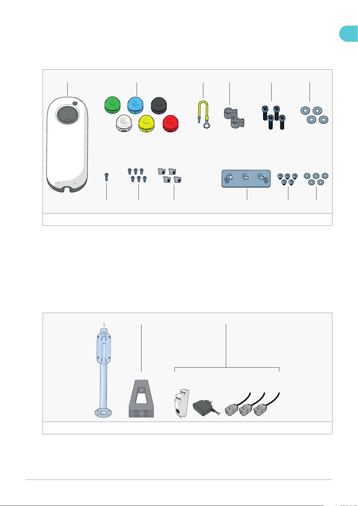
5.1. Scope of delivery/Check the contents
5.1.1. Home Advanced 2.1 / 2.2
1 2 3 4 5 6
789101112
5
1. Charge point (1×)
2. Coloured grommet 10 - 22.5 mm (6×)
3. Earthing wire (1×)
4. Plastic spacer (2×)
5. M8 × 35 mm Allen bolt (4×)
6. M8 washer - big (4×)
7. M8 washer - small (5×)
8. M8 × 12 mm PZ3 head bolt (5×)
9. Wall mounting bracket (1×)
For wall mount (use only if applicable)
10. M4 × 12 mm Torx bolt (6×)
11. M4 × 20 mm Torx bolt (1×)
12. RJ12 unshielded connector (4×)
5.1.2. Optional
1 2 3
6
1. Mounting pole
2. Concrete base
3. DPM module
EN

12Installation manual – NewMotion Home Advanced 2.1 / 2.2 - 071NMEN13
5.2. Installation materials (not provided)
5.2.1. Power cable
The electrician is responsible for selecting the power cable type and size & safety components appropriate for the
specic situation and according to local regulations;
• Wire for the current at the maximum charging speed of the charge point under continuous load;
• Calculate with a power factor of 0.8;
• Calculate with a maximum voltage drop according to the local rules & regulations;
• Use shielded cable for underground cabling;
• Cable thickness: Ø 10 - 22.5 mm;
• Wire cross section
- Solid wires: max. 10 mm2;
- Stranded wires: 6 mm2 with end ferrules.
NOTICE The charge point can be limited between 6 A and 32 A, as described in chapter 6.3. Switching on the product.
5.2.2. Data cable (optional)
Ethernet cable: Standard CAT5 or CAT6 UTP ground cable with T568B-wired RJ45 connectors;
DPM data cable: Standard CAT5 UTP ground cable with straight-wired RJ12 connectors (connectors provided).
5.2.3. Earthing
The electrician is always responsible for selecting a cable cross-section appropriate for the specic situation and
according to regulations;
• TN-system: PE-cable (PEN conductor is not allowed);
• TT-system: separately installed earthing electrode < 100 Ohm spreading resistance.
5.2.4. Required nominal input voltage at charge point
• Single phase*: 230 V ± 10 % - 50 Hz
• Triple phase*: 400 V (3 × 230 V + N) ± 10% - 50 Hz
* 3-phase charge point can also be connected to a 1-phase installation. In this case the charge point can
only charge on 1-phase. Only connect L1 on the terminal block of the charge point;
5.2.5. Electrical protection
• MCB: C-characteristic*;
• RCD: According to IEC 60364-7-722:2015 this charge point must be installed with at least an RCD type A**
• RCBO: with overcurrent- and residual-current detection as described above.
722.531.2.101 Except for circuits using the protective measure of electrical separation, each connecting point shall be
protected by its own RCD of at least type A, having a rated residual operating current not exceeding 30 mA.
Where the EV charging station is equipped with a socket-outlet or vehicle connector complying with the IEC 62196
series, protective measures against DC fault current shall be taken, except where provided by the EV charging station.
The appropriate measures, for each connection point, shall be as follows:
• RCD type B; or
• RCD type A and appropriate equipment that ensures disconnection of the supply in case of DC fault current above 6
mA.
RCDs shall comply with one of the following standards: IEC 61008-1, IEC 61009-1, IEC 60947-2 or IEC 62423.
NOTICE The charge point is supplied with a DC fault detection device certied according to IEC 62955.
* The installer must select a suitable MCB to match the current setting of the charge point, taking into
EN

13Installation manual – NewMotion Home Advanced 2.1 / 2.2 - 071NMEN13
account MCB manufacturer specications and EV-Ready guidelines;
** The electrician is responsible to select a suitable RCD to match the local rules and regulations. Please
note that these may be different from the international rules and regulations.
NOTICE The charge point can be limited between 6 A and 32 A, as described in chapter 6.3. Switching on the product.
5.2.6. Charge point mounting
For wall mounting, use 5 × coach screws (6.3 × 70 mm), washers and plugs.
For pole mounting on a concrete base, use ll sand to cover the hole of the concrete base for optimal stability.
5.2.7. Installation tools and materials
Make sure to have a basic electricians toolkit when installing a NewMotion charge point.
Icon Description
Cabled ethernet connection.
Data cable tester (RJ12 & RJ45).
DPM module.
Fill sand.
Cellular signal strength measuring tool.
Pencil.
Plug for mounting in wall (if applicable).
Power drill and drill bits.
PZ3 PZ3 screwdriver.
RJ12 crimp tool.
EN

14Installation manual – NewMotion Home Advanced 2.1 / 2.2 - 071NMEN13
Icon Description
RJ45 crimp tool.
Spirit level.
Tape measure.
This is optional.
T20 Torx screwdriver (T20).
Voltage tester.
Caliper.
EN

15Installation manual – NewMotion Home Advanced 2.1 / 2.2 - 071NMEN13
5.3. Preparation
1. Cut the power to the circuit on which you plan to install the charge point.
2. Prepare the cabling, RCD and MCB according to local rules and regulations. It is also possible to use an RCBO if
local rules and regulations allow it.
3. Apply labelling to the used circuit on the consumer unit for future reference.
4. Update the schedule of circuits to include the charge point installation
5. Apply proper lockout-tagout equipment for personal safety.
6. Use a GPRS signal strength measuring tool to determine if the signal is strong enough for network communication
via GPRS. The minimum signal strength for a stable connection is -80 dBm.
7. If the signal strength is not strong enough, or if you are not able to measure the signal strength, prepare an Ethernet
cable from an internet enabled router to the charge point location.
NOTICE Do not strip or attach a connector to the Ethernet cable on the charge point side yet.
8. Label the Ethernet cable on the charge point side for reference during installation.
9. If you have purchased a DPM module along with the charge point, prepare a DPM data cable from the consumer
unit to the charge point location.
NOTICE Do not strip or attach a connector to the DPM data cable on the charge point side yet.
7
10. Twist the socket lid counterclockwise and pull it from the cover (see gure 712).
11. Pull the cover from the casing to open the charge point and access the internal components (see gure 73).
12. Check if all the connected wiring and internal components of the product are properly fastened.
EN
16Installation manual – NewMotion Home Advanced 2.1 / 2.2 - 071NMEN13
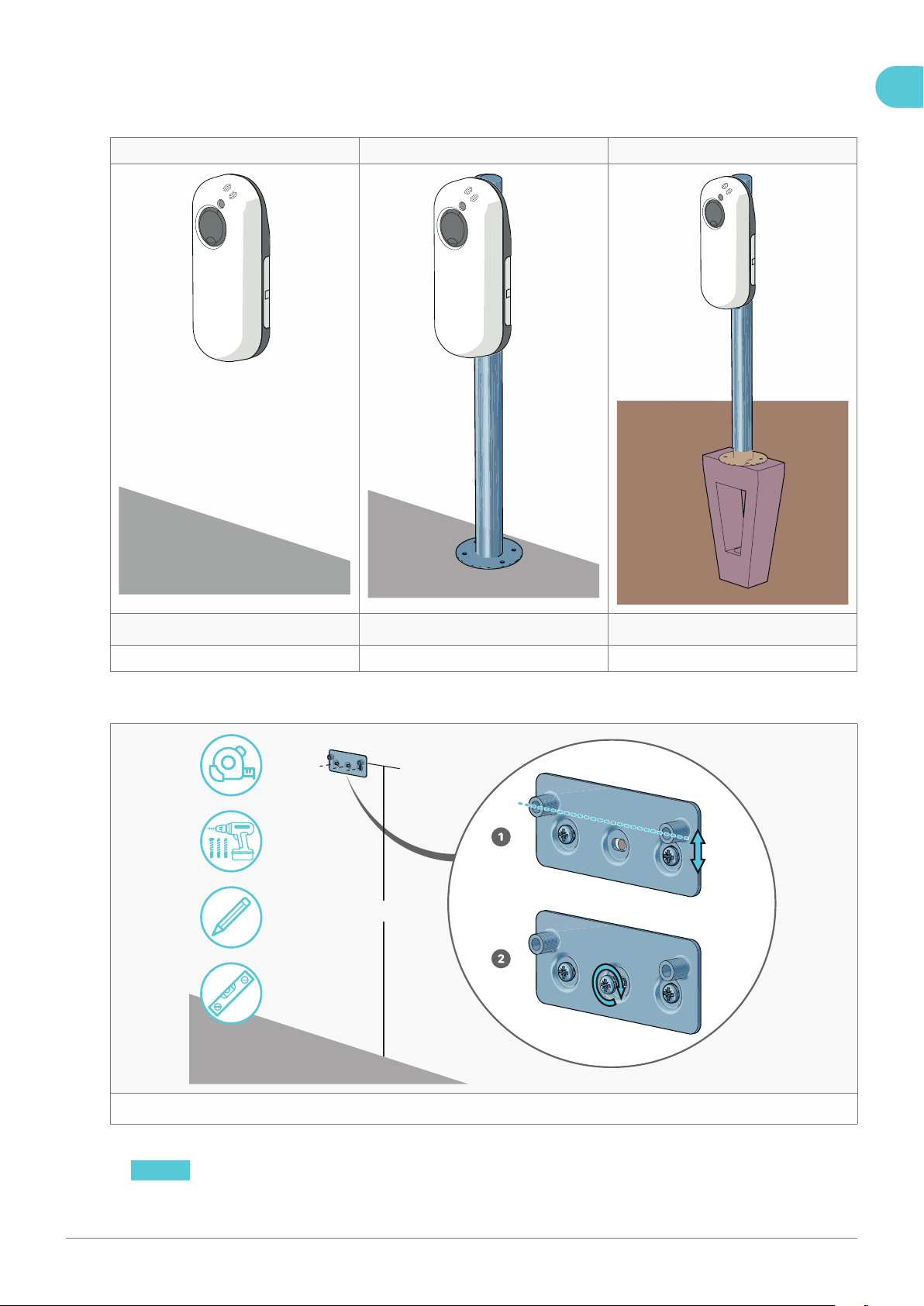
5.4. Mounting
Check the applicable method of installation and continue to the assigned chapter.
Wall mount Pavement mount Soil mount
89q
Go to chapter 5.4.1. Wall mount Go to chapter 5.4.2. Pavement mount Go to chapter 5.4.3. Soil mount
5.4.1. Wall mount
±90 cm
w
1. Secure the wall bracket to a wall at the appropriate height (± 90 cm) (see gure 11).
NOTICE Make sure the wall is strong enough to withstand the weight of the charge point.
EN

17Installation manual – NewMotion Home Advanced 2.1 / 2.2 - 071NMEN13
e
2. Place the casing on the wall mount and mark the locations for the bottom fasteners (see gure 12).
3. Remove the casing from the mount and drill two holes for the bottom fasteners.
NOTICE Check the fastener package for the correct diameter and depth.
4. Insert two wall plugs into the holes (if applicable).
T20
Ø10 - 13 mm
Ø13 - 15.5 mm
Ø15.5 - 18 mm
Ø18 - 21 mm
Ø21 - 22.5 mm
r
5. Remove the rear cable clamp (see gure 131).
6. Place the plastic spacers on the back of the casing (see gure 132).
7. Insert the coloured grommet matching the power cable thickness into the rear input hole (see gure 133).
NOTICE Use a caliper to measure the thickness of the power cable and determine the correct coloured grommet.
8. Feed the power cable approx. 15 cm through the coloured grommet. Lubricate if necessary (see gure 134).
EN
18Installation manual – NewMotion Home Advanced 2.1 / 2.2 - 071NMEN13
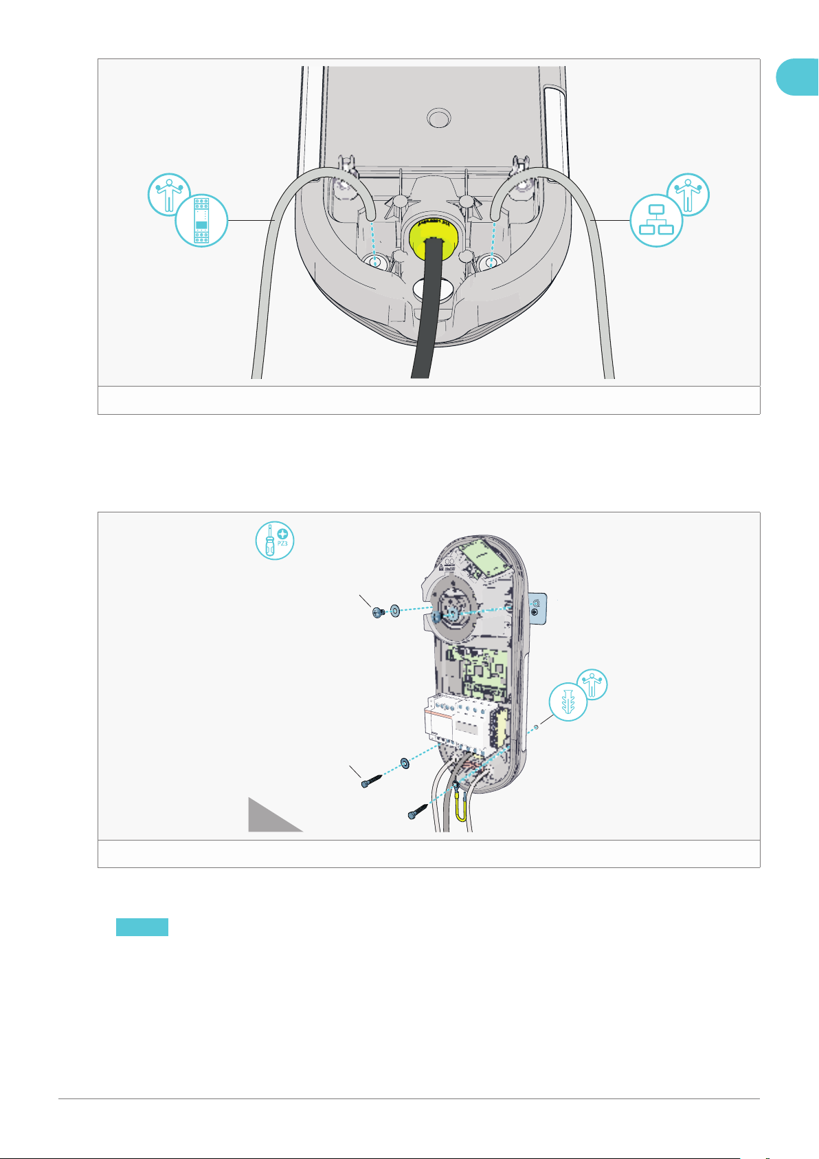
t
The next three steps are optional (see gure 14):
9. Punch a hole in the grey grommet(s) for the data cable(s) using a screwdriver.
10. Feed the DPM data cable through the right grommet.
11. Feed the Ethernet cable through the left grommet.
M8 × 12 mm
Coach screw
(6.3 × 70 mm)
y
12. Secure the casing to the wall using 2 provided M8 × 12 mm bolts, 3 M8 washers and 2 coach screws (not provided)
(see gure 15).
NOTICE Secure the supplied earthing cable between the casing and the bottom right screw, if required by local
rules and regulations.
EN
19Installation manual – NewMotion Home Advanced 2.1 / 2.2 - 071NMEN13
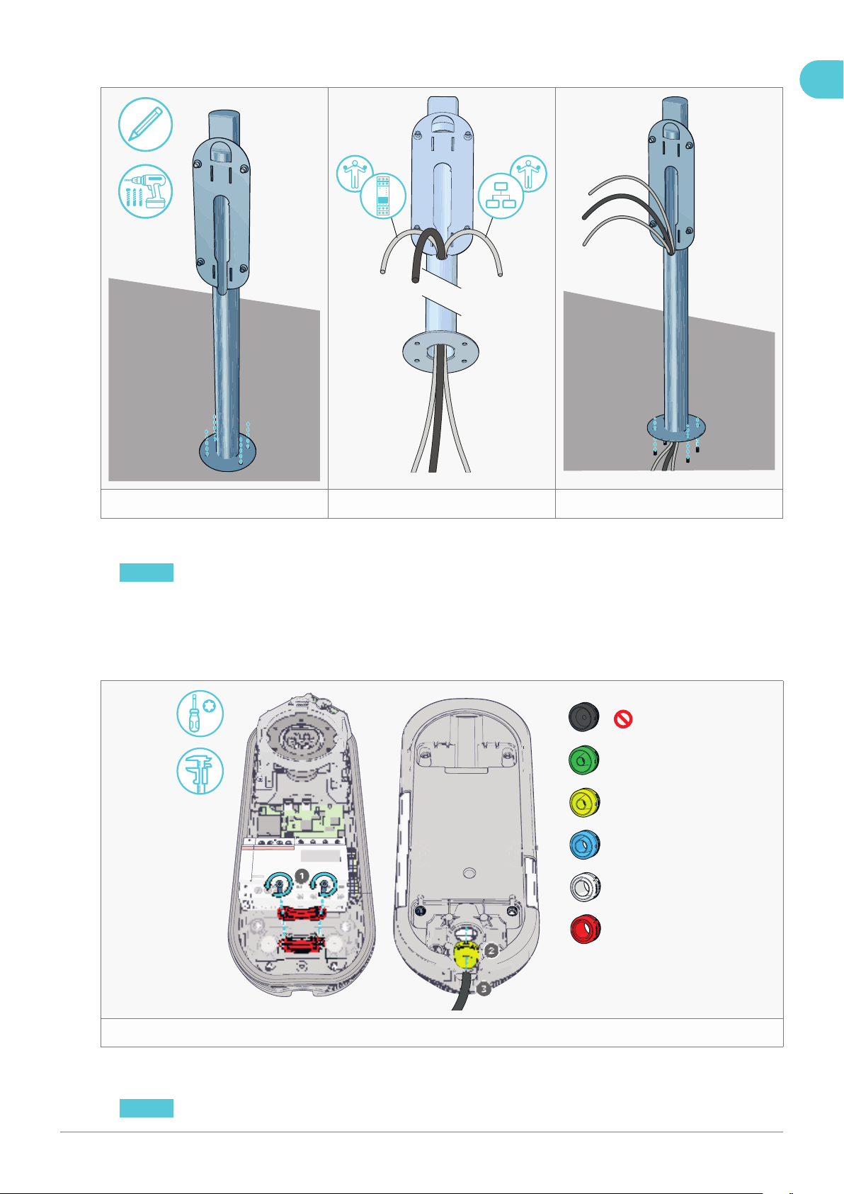
5.4.2. Pavement mount
uio
1. Place the pole on the pavement and mark the locations for the holes (see gure 16).
2. Remove the pole and drill holes into the pavement for the wedge bolts or chemical anchors.
NOTICE Check the fastener package for the correct diameter and depth.
3. Secure the fasteners into the holes. Allow the chemical anchor to dry, if applicable.
4. Feed the power cable and optional data cable(s) through the pole (see gure 17).
5. Secure the pole to the fasteners using 4 washers and nuts (not provided) (see gure 18).
6. Remove any excess threaded rod, if necessary.
T20
Ø10 - 13 mm
Ø13 - 15.5 mm
Ø15.5 - 18 mm
Ø18 - 21 mm
Ø21 - 22.5 mm
p
7. Remove the rear cable clamp (see gure 191).
8. Insert the coloured grommet matching the power cable thickness into the rear input hole (see gure 192).
NOTICE Use a caliper to measure the thickness of the power cable and determine the correct coloured grommet.
EN

20Installation manual – NewMotion Home Advanced 2.1 / 2.2 - 071NMEN13
9. Feed the power cable approx. 15 cm through the coloured grommet. Lubricate if necessary (see gure 193).
a
The next three steps are optional (see gure 20):
10. Punch a hole in the grey grommet(s) for the data cable(s) using a screwdriver.
11. Feed the DPM data cable through the right grommet.
12. Feed the Ethernet cable through the left grommet.
M8 × 12 mm
s
13. Secure the casing to the pole using 4 provided M8 × 12 mm bolts and washers (see gure 21).
NOTICE Secure the supplied earthing cable between the casing and the bottom right screw.
EN
This manual suits for next models
1
Table of contents
Other newmotion Automobile Accessories manuals

newmotion
newmotion Business Lite View User manual

newmotion
newmotion Home Basic User manual

newmotion
newmotion Business Lite View User manual

newmotion
newmotion Business Lite View User manual

newmotion
newmotion Dynamic Power Management Home - Module User manual

newmotion
newmotion Home Advanced View User manual
Popular Automobile Accessories manuals by other brands


SmartGauge
SmartGauge PowerGuard Owners and installation manual

Volvo
Volvo Navigation System installation instructions

Curt Manufacturing
Curt Manufacturing 58957 installation manual

Belkin
Belkin WIC004 Setting up

Axxess
Axxess AX-GMCL2-SWC installation instructions

SuperATV
SuperATV TSK-CA-DEF-004 installation instructions


