AUTOLIFT F900 User manual


-1-
1-SAFETY
Always take following safety precautions when using the Lift F900:
A-The vehicle must be parked in a flat ground. If the vehicle is parked on a slop, the use of the lift could be
dangerous.
B- The vehicle must always be safely parked, with emergency brake engaged before using the lift.
C- Always read carefully the safety instructions
D-When using the lift, the person on wheelchair must be facing outwards, meaning that the larger diameter
wheels must be turned towards the vehicle being loaded.
E- During the operations the person on the wheelchair must be in the centre of the platform, block the
parking brakes, and check that the wheels are not blocking the roll-stop and bridgeplate
F-The max load capacity is 300 KG.
G- Make sure that nobody is staying in the moving area of the lift. Always check that arms, feet, legs oder
clothes are not close to the moving parts of the lift
H- Only trained personell can operate the lift. No more people simultanously over the person on wheelchair
are allowed to be transported on the lift. Make sure that weights or persons are not staying on the platform
when it is moving IN and OUT of the Box. .
I-After the operations always return the lift in to stowage position
2- LIFT USER
The lift user hast o read this manual carefully and understand the instructions. Before starting to use the lift,
the user has to train and learn all functions without load. The user is responsible for the correct use (as
described in this manual) of the lift , for the maintanance and eventual manipulation oft he device, that could
cause hazardous conditions.
3- MAIN PARTS
Lift “F900”
Hydr. Power pack box
Electric controller box
Hand control
Aluminium Platform
Stainless Steel Box
Roll-Stop Barrier
Bridge Plate

4- HOW TO OPERATE THE LIFT
Before using the lift, the vehicle must be safely parked with emergency brake engaged and warning flashing
lights on. The operation is done through the Hand Control :
4.1 How to get in the vehicle
-Push “OUT” until the platform is completely out of the box
-Push “DOWN” until the platform is on the the ground and the roll stop is horizontal
-Wheelchair occupant gets on the platform
-Push “UP” and raise the lift up to the vehicle floor level
Wheelchair occupant gets in the vehicle
-Push “IN” , the lift will lower automatically to central position level and will stow in the box
Lift “F900”
Platform “OUT”
Platform “UP”
Platform “IN”
Platform “DOWN”

4.2 How to get off the car
-Push “OUT” until the platform is completely out of the box
-Push “UP” and raise the lift up to the vehicle floor level
-Wheelchair occupant moves from the vehicle cabin on the platform
-Push “DOWN” until the platform is on the the ground and the roll stop is horizontal
- Wheelchair occupant leaves the platform
-Push “UP” until the platform raises over the central position level
-Push “IN” , the lift will lower automatically to central position level and will stow in the box
4.3 Precautions
During the operations the person on the wheelchair must be in the centre of the platform, block the parking
brakes, and check that the wheels are not blocking the roll-stop and bridgeplate
The vehicle must always be safely parked, with emergency brake engaged before using the lift.
Make sure that nobody is staying in the moving area of the lift. Always check that arms, feet, legs oder
clothes are not close to the moving parts of the lift
Only trained personell can operate the lift. No more people simultanously over the person on wheelchair are
allowed to be transported on the lift. Make sure that weights or persons are not staying on the platform when
it is moving IN and OUT of the Box. .
When using the lift, the person on wheelchair must be facing outwards, meaning that the larger diameter
wheels must be turned towards the vehicle being loaded.
Lift “F900”

5-EMERGENCY OPERATIONS
5.1 Manual Movement of the Platform
The Platform can be manually pulled out and stowed again in the box. To operate it , just pull the
emergency wire (see Picture) that is placed in the right platform corner.
5.2 Emergency Lifting
1. Plug the lever in to the hand pump handle (Picture 1+ 2)
2. Move lever up and down
3. Using the hand pump lift the platform to the required height
4. Put the lever back in to its fixation
5. Contact an Autolift distributor or service point
Picture-1 Picture-2
5.3 Emergancy Lowering
1. Don’t remain in the area of the platform
2. Use the lever to open the lowering valve (Picture 3+4)
3. Very Slowly turn the valve clockwise and lower the platform carefully,
to the desired height. Don’t open to much otherwise the movement
could be to fast and could be dangerous
4. Close the valve by turning it anti-clockwise
Picture-3 Picture-4
Lift “F900”
Platform emergency
wire

5-EMERGENCY OPERATIONS- Version with Hydr. Unit placed under the vehicle
5.1Manual platform movement (In –Out)
The Platform can be manually pulled out and stowed again in the box. To operate it , just pull the
emergency wire (see Picture) that is placed in the right platform corner.
.
5.2 Emergency Lifting
1. Plug the lever in to the hand pump handle (Picture 1+ 2)
2. Move lever up and down
3. Using the hand pump lift the platform to the required height
4. Put the lever back in to its fixation
5. Contact an Autolift distributor or service point
Picture-1 Picture-2
5.3 Emergancy Lowering
1. Don’t remain in the area of the platform
2. Use the lever to open the lowering valve (Picture 3+4)
3. Very Slowly turn the valve clockwise and lower the platform carefully,
to the desired height. Don’t open to much otherwise the movement could be to fast and could be
dangerous
4. Close the valve by turning it anti-clockwise
Picture-3
Sollevatore “F900”
Cable for emergency
platform movement

6-CHECKS AND MAINTENANCE
6.1 CHECKS
Check before and after installation PR
The Underflor Lift F900 was previously checked in Autolift before dispatch. After Installation in to the
vehicle a trained person will have to do the described checks and confirm it on the attached Document.
In case of positive check , the lift is than approved and can be used.
It is forbidden to use the lift, if it has not been checked after installation in the vehicle.
Regular check
Beside the described checks , the lift must be checked by a trained person at least on yearly base and the
result must be confirmed in writing.
Extra Check
In case of repair or extraordinary mantainance the check must be executed by a trained person , which
work will follow anyway the regular check schematic.
Trained person
A person that with know-how and experience, that is in a position to evaluate the condition of wheelchair
lifts and safety of the users.
.
Necessary Checks
Result
-
-
-
-
-
-
-
-
-
-
Handcontrol is good condition and wire is not damaged
Fixing supports are well mounted , correctly fixed and in good conditions
All screws are well tighned
Bearings are well mounted and in the right position
Platform can freely move and no parts interfear with its movements
Bridge plate works correctly and can move freely
Bridge plate is horizontal when platform is at vehicle floor level
The Roll- Stop plate works correctly and moves freely when platform is on the
ground
Hydraulic cylinders and pipes do not show any leackage
Hydraulic pipes are not damaged
Lift “F900”
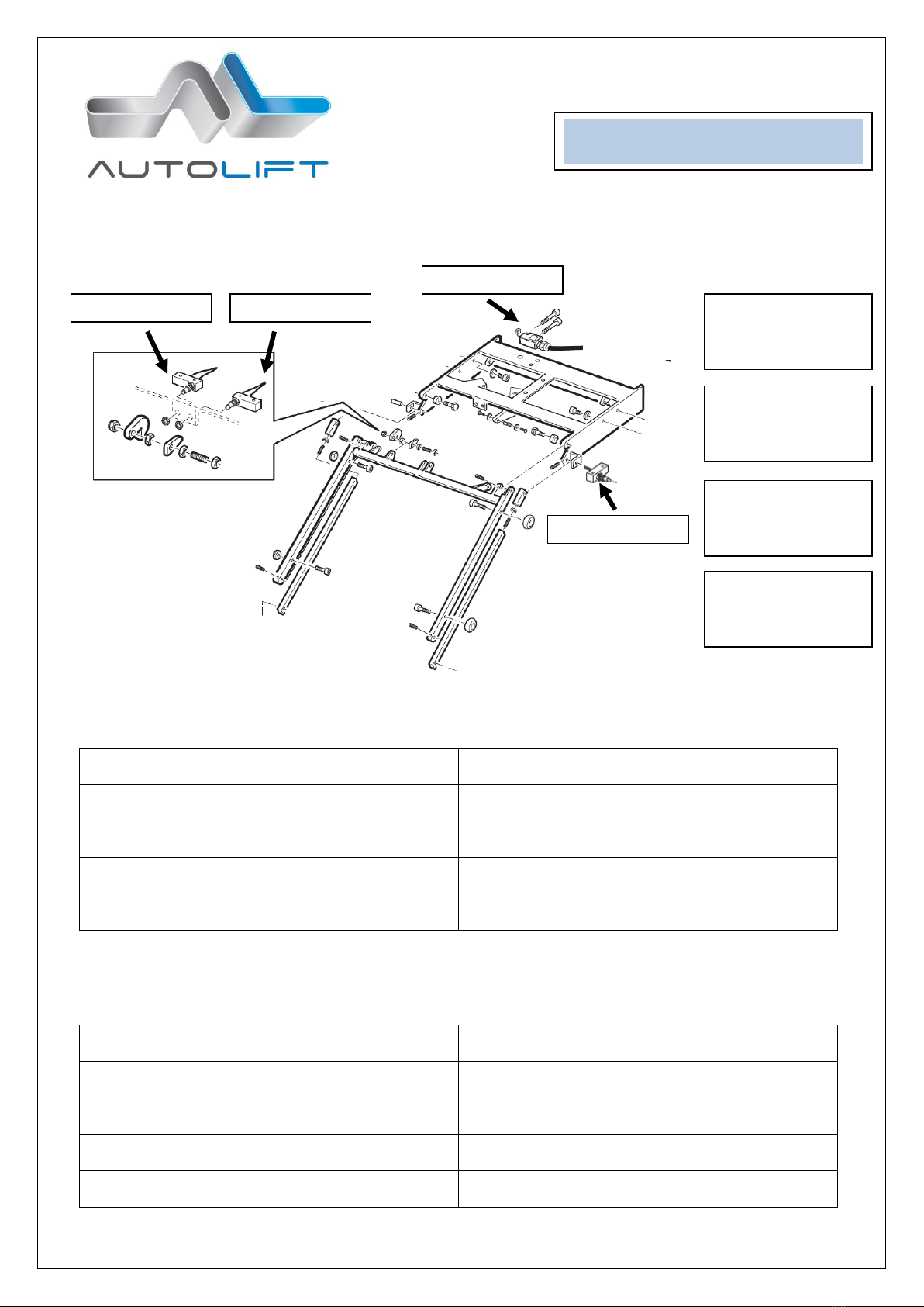
6.2 SETTINGS
By changing the position of the cams it is possible to re-set the central position level and the upper position
(vehicle floor level)
CENTRAL POSITION –Microswitch A
Platform too HIGH
Platform too LOW
A.Drive platform out of box
A. Drive platform out of box
B.Lower the Lift
B.Raise the Lift
C.Knock lightly the Cam A from the top (max 1mm)
C. Knock lightly the Cam A from the bottom (max
1mm)
D.Stow the lift back in the box (lift over central
position an than push button “in”
D. Stow the lift back in the box (push button “in”)
UPPER POSITION –Microswitch B
Platform too HIGH
Platform too LOW
A.Drive platform out of box
A. Drive platform out of box
B.Lower the Lift
B.Raise the Lift
C.Knock lightly the Cam Bfrom the top (max 1mm)
C. Knock lightly the Cam B from the bottom (max
1mm)
D.Stow the lift back in the box (lift over central
position an than push button “in”
D. Stow the lift back in the box (push button “in”)
MICROSWITCH A
regulate the central
position level
MICROSWITCH B
regulates the upper
position level
Lift “F900”
MICROSWITCH C
gives signal of lift
completely “stowed”
MICROSWITCH D
gives signal of lift
completely “out”
Microswitch A
Microswitch B
Microswitch C
Microswitch D

6.3 POSSIBLE FAILURES
First check that the battery level is acceptable
Failure
Ev. Cause
Solutions
1.Platform does’t get out of box
1.Hand control not working
2.Microswitcht A is not working
1.Check hand control and ev.
change it
2.Move manually the microswitch
pin
2.Platform is on the floor and
doesn’t raise
1.E-Motor Relais / Hand control
not working
2. Platform is accidentally been
pushed back in box
1. Check parts and change them
2. Push “out” or pull manually the
platform back entirely out from
box
3. Platform doesn’t lower
1. Hand control not working
2. Lowering valve is not working
1. Operate the lift manually and
change as soon as possible the
parts
4.Platform doesn’t lower and stow
from upper position
1. Microswitch D doesn’t work –
pin is blocked
1.Move the Microswitch pin until it
works again
7- NEW FUEL TANK
A new vehicle tank will be built, in order to reach the necessary clearance from the ground
While refueling do not overfill the tank.
Please note that the fuel level indicator of the vehicle is not precise anymoret.
Therefore use the tachometer to calculate the total or remaining km autonomy.
This way you will prevent unexpected stops because of missing fuer and unuseful service costs
Lift “F900”
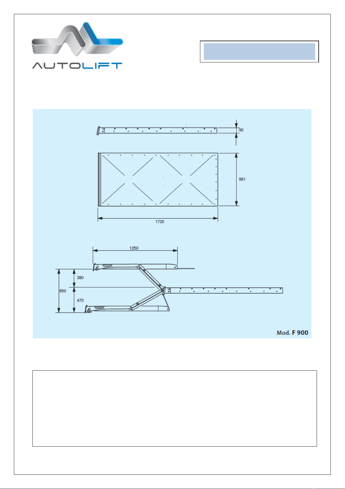
8- TECHNICAL DATAS
TECHNISCHE DATEN
TECHNICAL FEATURES
Model:
F900
Model:
F900
Tragkraft:
300 Kg
Loading capacity 300Kg
Eigengewicht:
135Kg
Weight:
135Kg
Spannung:
12 Volt
Electrical System: 12 Volt
Oeldruck max:
200 Bar
Max Air Presure: 200 Bar
Piattaformgroessen:
800 x 1250mm
Platform Dimension: 800 1250
Hubhoehe:
850mm.
Max.Floor Height: 850mm
Notpumpe und Notabsenkventil
Emergency auxiliary manual pump.
Lift “F900”

9 -HYDRAULIC DIAGRAM
The hydraulic unit is built in a protection box and can be placed inside the vehicle in preferred position. The
emergency pump and emergency lowering valve are accessible with out removing the box cover and this
allows the user an easier use of the lift also in case of emergency and battery failure.
Lift “F900”
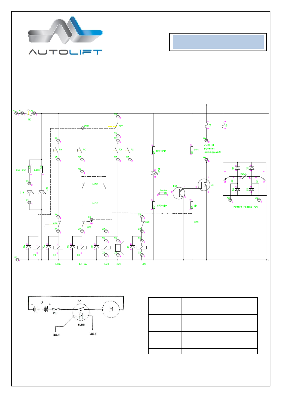
10 –ELECTRIC DIAGRAM
Control Unit (Printed circuit)
Power Unit
POSITION
CORRESPONDANCE
X2
Platform El. Motor
X6
Flashing lights
TLRS
Starting Relais
BZ1
Acustic Warning
EVB
Lowering valve
Entra
Platform in
Esce
Platform out
MC1
Microswitch for Platform Height
MC2
Microswitch for Platform Height
Lift “F900”

11 –EXPLODED VIEW
Lift “F900”

Other manuals for F900
1
Table of contents
Popular Automobile Accessories manuals by other brands

Over Armour Offroad
Over Armour Offroad CA-MAVERICKX3-4-TC01 Instructions for Installation and Care

Feniex
Feniex T3 instruction manual

DoubleTake
DoubleTake SeatBack Plates installation instructions

Metra Electronics
Metra Electronics 99-5800 installation instructions

Aim
Aim X90BGGK12MA user manual

Boyo Vision
Boyo Vision VTC1743M user manual


AL-KO
AL-KO G&S Chassis Caravan Warranty and Service Hand book

ICI
ICI Alumilite Steps 840121412920 Direction for Installation and Use

Dakota Digital
Dakota Digital BIM-16-1 manual

Kensington
Kensington K33440US Instruction guide

Brodit
Brodit 804741 ProClip installation instructions

Rhino-Rack
Rhino-Rack RCP58-BK manual