newmotion Home Advanced View User manual

INSTALLATION MANUAL
Home Advanced View
3,7 - 22 kW
INSTRUCTION MANUAL – EN | INSTALLATIONSANLEITUNG - DE
VERSION 075NM19INT01


NewMotion
Home Advanced View
3,7 - 22 kW
Table of contents /
Inhaltsverzeichnis
DE: +49 (0)30 215 028 48
Instruction manual (EN)
Pages 4 - 16
Installationsanleitung (DE)
Pagina 17 - 30

INSTALLATIEHANDLEIDING – P4 VERSION 0129NM02INT01INSTRUCTION MANUAL – P4 | P4 075NM19INT01
EN DE
1.1 PRODUCT DESCRIPTION &
INTENDED USE
Thank you for choosing a NewMotion Electric Vehicle
(EV) Charge Point.
This charge point is intended to charge the batteries within
EVs compatible with IEC-61851 MODE3 denition and
requirements. Dedicated EV specic plugs will need to be
utilised. No adaptors, conversion adaptors or extension
sets for cables are allowed to be used. EVs and cables
used with this charge point should always be undamaged
and in their original state.
This charge point is M&E-compliant, a Secured Mess &
Eichrecht Device (SMED) is build upon the existing ener-
gy meter inside the charger. All legal relevant data from
each transaction is stored inside this device. It’s possible
for users to read and access live- and historical data on
the LCD display screen.
1.2 SAFETY WARNING + CAUTION!
The electrical system must be voltage-free during the
entire installation procedure. Failing to do so can lead to
serious injury or even death. The installation procedure
must be carried out by a trained electrician who works in
accordance with all relevant local laws and regulations.
Do not install in potentially explosive atmospheres and/
or zones with high electromagnetic radiation and/or in
ood-prone areas.
The charge point is connected to the electricity grid and
even if the equipment is switched o, hazardous voltag-
es may be present at the input terminals. Always switch
o the AC supply before starting any work on the charge
point and/or its installation. Do not carry out any work
in rainy conditions or when the humidity is above 95%.
The safety guidelines are intended to ensure correct in-
stallation and usage. Any failure to comply with the valid
safety guidelines or instructions provided in this manual
may result in re, electrocution or severe injury.
The charge point is a product in Safety Class I and is
supplied with an earth terminal for protection purposes.
The AC input clamps must be tted with an uninterruptible
earth for protection purposes. Ensure that the connection
cables are tted with fuses and circuit breakers. Never
replace a protection component with another type. First
check the full installation to determine if that component
can be used with the existing installation components.
Before you switch on the charge point, check that the
available power source matches the conguration set-
tings of the product, as described in this manual.
Tripping of the RCD could be caused by an earth fault
or a defect relay. If, after resetting the RCD, the device
cannot be activated or immediately trips again; please
contact NewMotion or your installer.
1.3 LEGAL DISCLAIMER
This manual is created for you with care.
We however do not guarantee that all information is
complete, accurate and correct. Please check our
website www.newmotion.com for the latest version of
this manual. We strongly advise you to have our product
installed by certied professionals. How our product
should be installed and used depends on local circum-
stances and local and national regulation, which are not
mentioned in our manual. NewMotion is not responsible
for any loss or damage whatsoever caused – including
without limitation, any indirect, personal or consequen-
tial loss or damage - arising from or in connection with
the use of this manual. Nor does NewMotion accept any
liability for any such loss or damage arising out of your
reliance on any information contained in this manual.
1. INTRODUCTION

INSTALLATIEHANDLEIDING – P5 VERSION 0129NM02INT01INSTRUCTION MANUAL – P5 | P5 075NM19INT01
EN DE
To ensure the charge point is ready for use, the owner
needs to activate the charge point through our online
portal at my.newmotion.com. The serial number of the
charge point is needed for this process which can be
found on the right hand side of the charge point.
Charge cards can be activated in the same online portal.
2. ACTIVATING CHARGE POINT BEFORE USE

INSTALLATIEHANDLEIDING – P6 VERSION 0129NM02INT01INSTRUCTION MANUAL – P6 | P6 075NM19INT01
EN DE
Way of mounting
Standard: charge
point wall bracket
mounting
Optional pole
mounting
Optional concrete
base (for in soil) for
pole
Optional Wall bracket
for two NewMotion
charge points
Required tools & additional materials
(not provided)
- Installation materials (power cable and
cable mount clips, RCD(‘s), MCB(‘s), etc);
- UTP cable(s) (CAT5 or CAT6);
- RJ45 UTP cable crimp tool;
- RJ12 crimp tool
- RJ45 connectors;
- 4 x screws (at least 6.3 x 60/70) and
plugs for mounting in wall;
- Drill and bit;
- Torx screwdrivers (T20 and T45);
- Voltage tester;
- Tape measure;
- Spirit level;
- All mentioned for standard mounting,
plus;
- Pole (sold separately);
- 4 x M8 wedge bolts or chemical
anchors, plus nuts and washers;
- All mentioned for pole mounting, plus;
- Concrete base (sold separately);
- DIN 912 HEX allen key (Size 6);
- Shovel;
- All mentioned for standard mounting,
plus;
- Pole (sold separately);
Package contents charge point
- Charge point;
- Wall bracket;
- Rubber grommets (various sizes);
- 2 x plastic spacers;
- Sticker sheet for the sides of the
charge point;
- 1 x M4 x 20 mm bolt (Torx);
- 6 x M4 x 12 mm bolts (Torx);
- 2 x M8 x 12 mm bolts (Torx);
- optional attached tethered
charge cable
- 4 x RJ12 6P6C connectors (for DPM)
- 4 x M8 x 12 mm bolts (Torx) plus
washers;
- 4 x M8 x 35 mm bolts (HEX DIN 912)
plus washers;
- 4 x M8 x 12 mm bolts (Torx) plus
washers;
3. PRODUCT OVERVIEW
3.1 MOUNTING OPTIONS, PACKAGE CONTENTS AND REQUIRED TOOLS

INSTALLATIEHANDLEIDING – P7 VERSION 0129NM02INT01INSTRUCTION MANUAL – P7 | P7 075NM19INT01
EN DE
3.2 TECHNICAL SPECIFICATIONS
3. PRODUCT OVERVIEW
CONTINUED ON NEXT PAGE
Serial number format Home Advanced View
Maximum charge capacity
Standard congured charge capacity
Electric safety category
DC-fault current protection
Dimensions (H x W x D)
Weight
Standard colours
IEC-62262 IK code (robustness)
IEC-60529 IP code (protection class)
EN-50470 M-class
EN-50470 E-class
Certicates
kWh measurement
User interface
07 5 _ _ _ _ _
1-phase 32A (7,4 kW)*
3-phase 32A (22 kW)*
1-phase 16A (3,7kW)**
3-phase 16A (11kW)**
Class I & Class II ****
Built-in 6mA fault current protection
503.5 x 200 x 137 mm
± 4.2 kg
Rear side RAL 7031 (grey)
Front side RAL 9010 (white)
IK10
IP54 (for indoor and outdoor use)
M1
E2
IEC-61851-1
IEC-61851-22
EV-Ready & ZE-Ready
IEC-62262 -> IK10
IEC-60529 -> IP54
IEC-62955 -> 6mA DC-fault protection
MessEV & MessEG
MID certied (accuracy class B)
M&E certied
LED
LCD display
Proximity sensor-set

INSTALLATIEHANDLEIDING – P8 VERSION 0129NM02INT01INSTRUCTION MANUAL – P8 | P8 075NM19INT01
EN DE
* The maximum charge capacity of the charge point depends on several factors. This includes; local rules & regulations,
the type of EV, the grid connection at your location and the electricity usage of your building.
**Contact NewMotion for changing charge capacity.
***Contact NewMotion for further information: +44 20 3868 1036 and press option 1.
**** Product is tested and certied for both Class I & Class II. Method of mounting dictates which class is applicable;
Mounted on wall = Class II, mounted on the metal pole with Protective Earth connection = Class I.
3.2 TECHNICAL SPECIFICATIONS
3. PRODUCT OVERVIEW
Identication
Communication backoce
Communication Smart Meter
Backoce protocol
Stand-by consumption
Operating temperature range
Operating humidity range
Operating air pressure range
Maximum mounting height socket
Advised mounting height socket
Mounting position
Function for ventilation according to IEC-61851
RFID (NFC) Mifare 13.56 MHz
IEC 14443A
IEC 14443B
Plug & charge (through online portal)
GPRS 2G (minimal -80dBm Vodafone Partners)
Ethernet connection (DHCP, TCP 443, TCP80, TCP21)
GPRS 2/3/4G with mobile router***
Straight RJ12 (6P6C) wired CAT5 (max20m) - DSMR > 4.0
OCPP protocol
3-6W
-30°C to +40°C
5% to 95%
860 hPa to 1060 hPa
1.5 meter above ground
1 meter above ground
Vertical and upright postion only
Not supported
INSTALLATIEHANDLEIDING – P9 VERSION 0129NM02INT01INSTRUCTION MANUAL – P9 | P9 075NM19INT01
EN DE
3. PRODUCT OVERVIEW
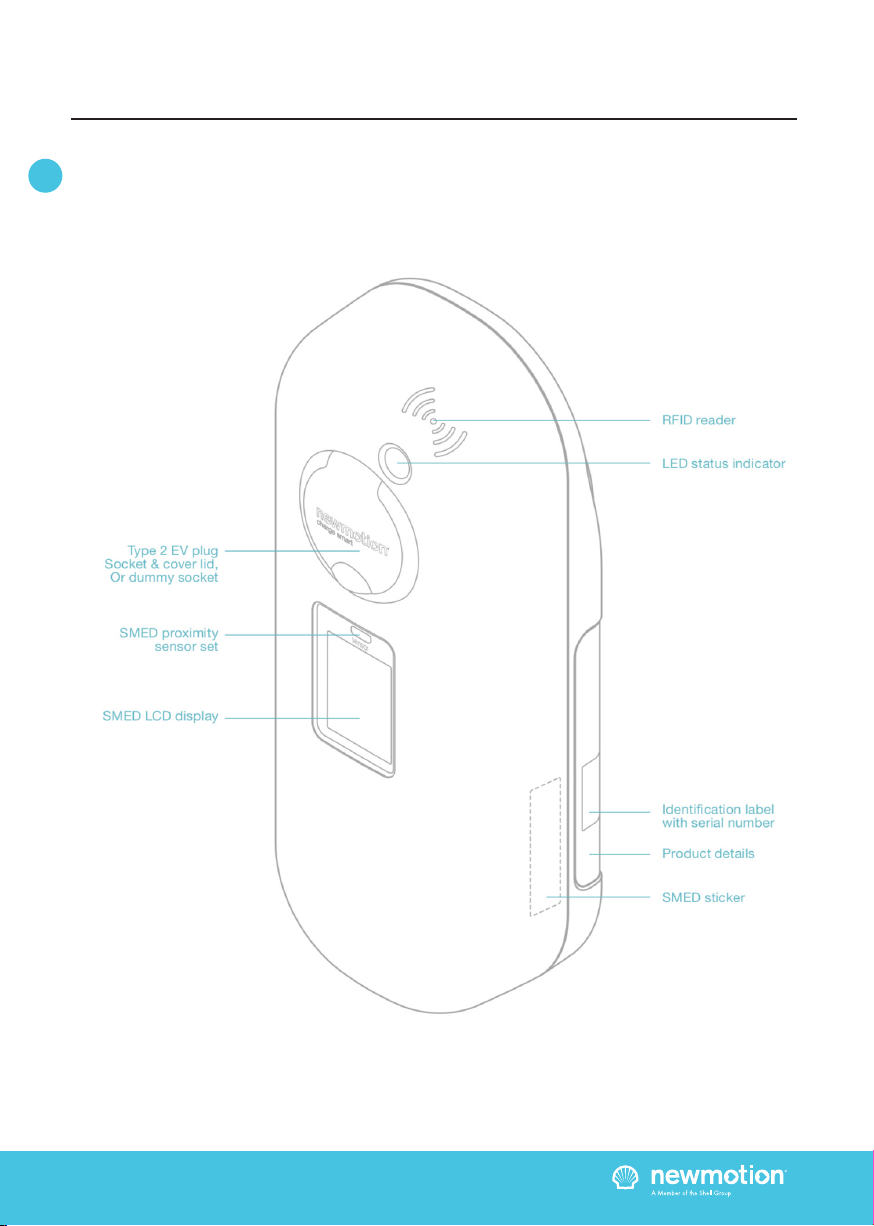
3.3 OVERVIEW OF PRODUCT

INSTALLATIEHANDLEIDING – P10 VERSION 0129NM02INT01INSTRUCTION MANUAL – P10 | P10 075NM19INT01
EN DE
3. PRODUCT OVERVIEW
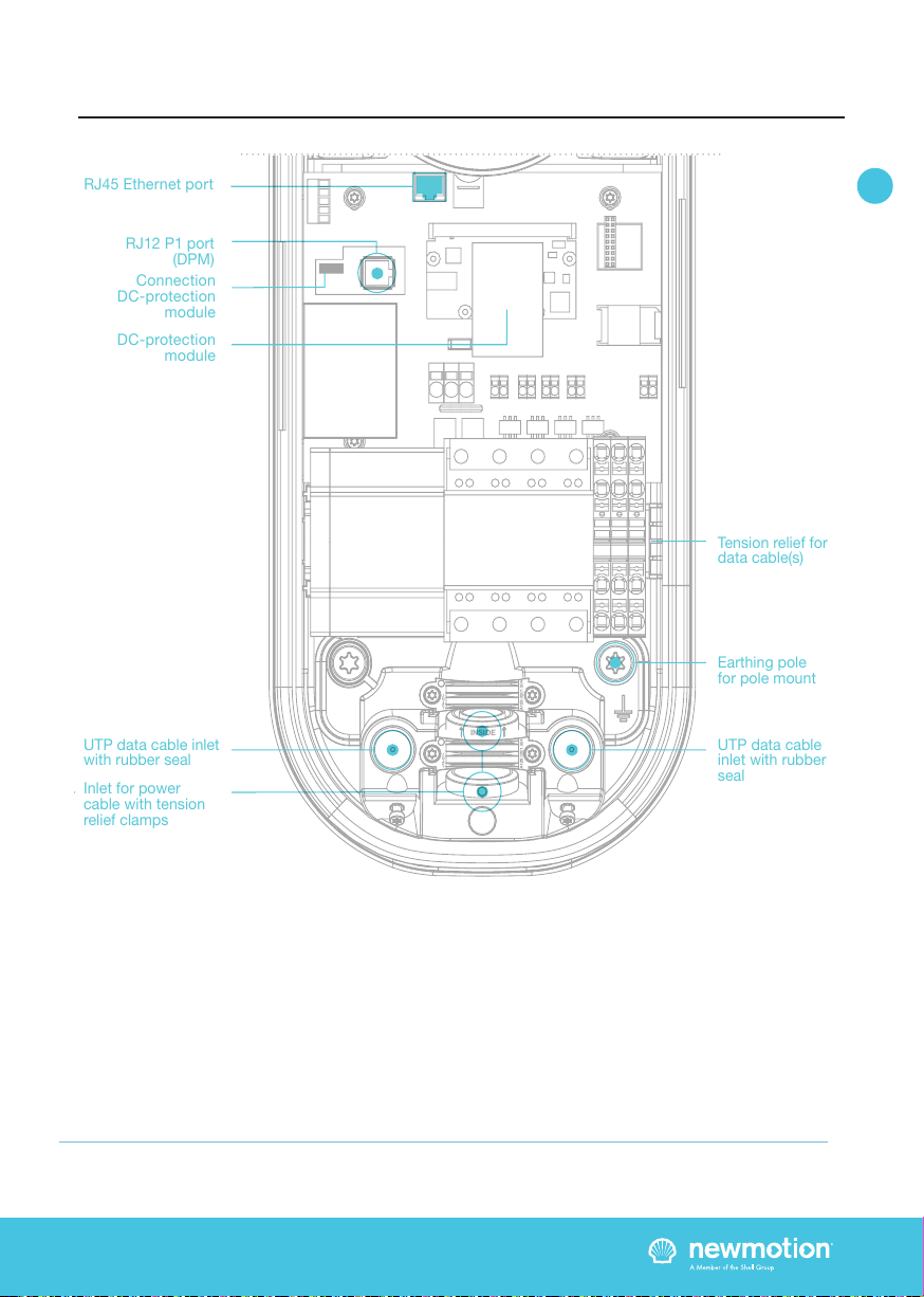
3.4 OVERVIEW OF CONNECTIONS
If connecting to a 3-phase grid without neutral; only install 1-phase and connect one of the two other phase
wires in the neutral wire connection on the terminal block.
INSIDE
INSIDE
RJ45 Ethernet port
RJ12 P1 port
(DPM)
Earthing pole
for pole mount
UTP data cable
inlet with rubber
seal
UTP data cable inlet
with rubber seal
Inlet for power
cable with tension
relief clamps
Terminal block
DC-protection
module
Connection
DC-protection
module
SMED with LCD
user display &
Proximity
sensor-set
Tension relief for
data cable(s)
L1
N
PE (earthing)
RJ45 Ethernet port
Phase 2
Phase 3
INSTALLATIEHANDLEIDING – P11 VERSION 0129NM02INT01INSTRUCTION MANUAL – P11 | P11 075NM19INT01
EN DE
3. PRODUCT OVERVIEW
INSIDE
INSIDE
RJ45 Ethernet port
RJ12 P1 port
(DPM)
Earthing pole
for pole mount
UTP data cable
inlet with rubber
seal
UTP data cable inlet
with rubber seal
Inlet for power
cable with tension
relief clamps
Terminal block
DC-protection
module
Connection
DC-protection
module
SMED with LCD
user display &
Proximity
sensor-set
Tension relief for
data cable(s)
L1
N
PE (earthing)
RJ45 Ethernet port
Phase 2
Phase 3
If connecting to a 3-phase grid without neutral; only install 1-phase and connect one of the two other phase
wires in the neutral wire connection on the terminal block.

INSTALLATIEHANDLEIDING – P12 VERSION 0129NM02INT01INSTRUCTION MANUAL – P12 | P12 075NM19INT01
EN DE
3.5 BACKOFFICE CONNECTIONS
The Home Advanced can be connected to the
NewMotion backoce in three ways:
1. Ethernet connection
2. GPRS 2G
3. 2/3/4G with NewMotion mobile router
The Home Advanced View will connect to the New
Motion backoce so settings can be changed remotely
and for remote support to be given. Without the
backoce connection, none of our online services can
be used.
3.5.1 HOME ADVANCED VIEW – ETHERNET /
NEWMOTION MOBILE ROUTER
Connecting the Home Advanced View to an ethernet or
mobile router can be done by connecting the network
to the left UTP Ethernet data port with a cable max 50
meter long.
Settings might have to be changed in the network to
allow the charge point to make a successful connection
to the NewMotion backoce.
The network should have:
- DHCP
- Port TCP 80 and 443 should be opened
- FTP port 21 should be opened
- All opened ports should be inbound and outbound
FTP is needed to update the rmware of the chargepoint
and exchange diagnostics.
3. PRODUCT OVERVIEW
(Mobile)
Router

INSTALLATIEHANDLEIDING – P13 VERSION 0129NM02INT01INSTRUCTION MANUAL – P13 | P13 075NM19INT01
EN DE
Wiring advice*
Power cable size
Earthing advice*
Required nominal
input voltage @
charge point
MCB
RCD
Ethernet connection
cable requirements
DPM cable
requirements
Ø 10mm - Ø 22,5mm
10mm2 solid wire
6mm2 stranded wire with end ferrules
PE-cable (PEN conductor is not allowed)
Separately installed grounding electrode
< 100 Ohm spreading resistance
230V +/-10% 50Hz
400V (3 x 230V+N) +/-10% 50Hz
Cable grommets sizes
Maximum cable terminal block
TN-system
TT-system
Single phase**
Triple phase**
4. INSTALLATION ADVICE
The electrician is responsible for selecting a cable thickness & safety components appropriate
for the specic situation and according to regulations;
* The electrician is always responsible for selecting a cable thickness appropriate for the specic
situation and according to regulations;
** 3-phase charge point can also be connected to 1-phase. In this case the charge point can only
charge on 1-phase;
*** The electrician must select a suitable MCB to match the amperage setting of the charge point,
taking into account MCB manufacturer specications;
NOTE: The charge point can be set between 10 A and 16 A / 32 A (depending on version);
- Wire for the maximum hardware amperage under continuous load;
- Calculate with a COS-Phi of 0.8;
- Calculate with a max allowable voltage drop over the cable of 2%;
- Use shielded cable for underground wiring;
C-characteristic***
30mA Type A (Hi), or 30mA type B
Standard CAT5 or CAT6 Ethernet cable (UTP cable with RJ45 connectors)
CAT5 ethernet cable with RJ12 (6P6C) straight connected. Maximum length 20m

INSTALLATIEHANDLEIDING – P14 VERSION 0129NM02INT01INSTRUCTION MANUAL – P14 | P14 075NM19INT01
EN DE
Thank you for installing this charge point.
Make sure there is enough space to properly do the work.
Ensure to work safely and take the safety of others into
consideration as well, always work according to local
safety regulations.
When selecting the mounting location of the charge point,
ensure that future maintenance work can be done easily.
5.1 PREPARATION
Step 1; Prepare the cabling (power & UTP) & RCD and
MCB (conform to local rules & regulations);
Step 2; Indicate which circuit(s) the charge point is
connected to the distribution board;
Step 3; Attach the appropriate stickers provided
(1-phase or 3-phase) to the sides of the charge point in
the designated indent spaces;
Step 4; Turn the socket lid or dummy socket anti-clockwise
and out of the cover of the charge point;
Step 5; Then pull the cover from the rear edge to open the
charge point. Do not use any objects or tools to do this;
5.2 MECHANICAL MOUNT
For standard wall mount proceed with 5.2a, for optional
pole mount on pavement proceed with 5.2b, for optional
pole mount in soil proceed with 5.2c;
5.2A MECHANICAL MOUNT (WALL)
Step 1; Attach the top of the wall bracket at the desired
height (+/- 90cm) on the wall.
Step 2; Put the charge point on the wall bracket to
check its placement. On the wall, mark the positioning
of the bottom two attachment points of the charge point
and select the appropriate xtures (plugs, screws and
washers).
Step 3; Secure the charge point to the wall bracket using
the two M8 x 12 mm bolts and washers provided.
Step 4; Secure the charge point to the wall using the
bottom two attachment points. Ensure that the grey
spacers are placed on the back of the charge point at
the bottom two attachment points.
5.2B MECHANICAL MOUNT (POLE ON
PAVEMENT)
Step 1; Drill holes into the pavement for the wedge bolts
or chemical anchors (not provided);
Step 2; Route the power cable(s) and UTP cable(s)
through the pole;
Step 3; Mount the wedge bolts or chemical anchor into
the pavement;
Step 4; Mount the pole to the threaded ends with
washers and nuts (not provided);
Step 5; Mount the green/yellow pole earthing wire to the
terminal block earthing connection;
Step 6; Secure the charge point to the pole bracket
using the four M8 x 12mm bolts and washers provided,
making sure to connect the pole earthing wire to the
bottom right bolt;
5.2C MECHANICAL MOUNT (POLE IN SOIL WITH
CONCRETE BASE)
Step 1; Dig the concrete base into the soil, make sure it
is steady and level;
Step 2; Route the power cable(s) and UTP cable(s)
through the pole;
Step 3; Mount the pole to the concrete base with the 4
bolts M8 x 35 and washers that are provided;
Step 4; Mount the green/yellow pole earthing wire to the
terminal block earthing connection;
Step 5; Secure the charge point to the pole bracket
using the four M8 x 12mm bolts and washers provided,
making sure to connect the pole earthing wire to the
bottom right bolt;
5.3 POWER CONNECTION
Step 1; Select the appropriate grommet(s) that suits
the cable(s) thickness and place it in the opening of the
power cable inlet. Moisten if necessary to make it easier
to feed the power cable through;
Step 2; Secure the power cable(s) using the cable
clamp(s);
Step 3; Mount the (closed) black grommet in the
remaining cable inlet to make the charge point watertight
(not applicable for tethered cable versions);
Step 4; Connect the power to the terminal blocks, like
indicated in the ‘overview of connections’ section;
5. INSTALLATION PROCEDURE

INSTALLATIEHANDLEIDING – P15 VERSION 0129NM02INT01INSTRUCTION MANUAL – P15 | P15 075NM19INT01
EN DE
5.5 COMMUNICATION CONNECTION(S)
For UTP connection (preferred) proceed with 5.5a,
for GPRS connection proceed with 5.5b;
(refer to 3.4 & 3.5 Product Overview)
5.5A COMMUNICATION CONNECTION(S) (UTP)
Step 1; Feed the UTP cable(s) through the rubber
stop(s) on the data cable inlet and then connect it to
the Ethernet port(s), like indicated in the ‘overview of
connections’ section;
Step 2; Connect the UTP to an internet enabled router
with DHCP;
5.5B COMMUNICATION CONNECTION(S)
(GPRS)
Step 1; Check and make sure signal strength
is sucient;
5.6 OPTIONAL DPM (PURCHASED
SEPERATLY )
Step 1; Make sure to follow the DPM installation manual
in conjunction with this manual.
Step 2; Check if the Phase 1 in chargepoint match the
Phase 1 of the DPM device. If not, correct that rst.
Step 3; Feed the UTP cable through the rubber stops on
the data cable inlet and then connect the RJ12 (6P6C)
connector
to the P1 port. Connectors on this cable should be
straight, which means the same order on both sides of
the cable.
Step 4; Contact New Motion after step 5.7 for activation.
5.7 FINISHING UP (CLOSE ENCLOSURE)
Step 1; Check and make sure that the rubber enclosure
seal is properly in place on the enclosure edge all
around;
Step 2; Place the enclosure cover on the charge point;
Step 3; Hand-tighten the four M4 x 12mm bolts provided
around the socket so that the cover closes on the rubber
seal but the rubber seal does not deform;
Step 4; Hand-tighten the other two M4 x 12 mm bolts
provided in the bottom of the cover;
Step 5; Turn the socket lid or dummy socket clockwise
in the cover and hand-tighten the M4 x 20mm bolt
provided;
Step 6; Switch on power to the charge point;
Step 7; Wait until charge point is fully started up (+/-10
minutes, LED should be o);
Step 8; Check that the charge point is connected to the
network. A quick check can be done via chargeportal.
newmotion.com/test. Simply enter the serial number
into the search eld and click “Search”. “Online” should
appear after the serial number. If “Online” does not
appear, check whether the charge point is properly
connected and try again. For persistent issues, please
contact NewMotion.
Step 9; If conguration of the charge point power
settings is needed (for example lower Amp settings)
please contact NewMotion;
5.8 CHECK FUNCTIONING
Step 1; Power on the chargepoint and let it start up (give
it a few minutes);
Step 2; Check start screen and connection, the display
should show the initial start screen as shown below;
Step 3; The date and time need to show up as grey
text. If it shows red text the SMED is not synchronised
(backoce connection issue) or not yet fully started up;
Step 4; You can refer to the user manual for more use
related instructions*;
*Alternatively the owner/operator manual can also be
consulted.
5. INSTALLATION PROCEDURE

INSTALLATIEHANDLEIDING – P16 VERSION 0129NM02INT01INSTRUCTION MANUAL – P16 | P16 075NM19INT01
EN DE
6.1 BEFORE USE: ACTIVATION &
REGISTRATION
To make the charge point ready for use the owner needs
to activate the charge point through our online portal
my.newmotion.com. The serial number of the charge
point is required for this process and can be found on the
right hand side of the charge point. Charge cards can be
activated in the same online portal.
6.2 REGULAR USE
The rst step is to connect your car to the charge point
by plugging in the charge cable.
If you are using Plug&Charge the session will start
automatically.
If you have to identify rst; swipe your charge card above
the LED.
The LED will ash green to authenticate the card and
after acceptance, the session will start. If the LED
ashes red, the session has not been accepted.
When the car has delayed charging congured, the LED
will remain green until charging can start between the
car and charge point.
Start charging? Plug in & identify
Stop charging? Identify & unplug
Full or waiting to charge
Plug in or identify
Charging
Not accepted
Error
Flashing green or multi colors: starting procedure or
software update procedure for charge point.
6. PRODUCT USE / OPERATION

INSTALLATIEHANDLEIDING – P17 VERSION 0129NM02INT01INSTALLATIONSANLEITUNG – P17 | P17 075NM19INT01
EN DE
1.1 PRODUKTBESCHREIBUNG &
VERWENDUNGSZWECK
Vielen Dank, dass Sie eine Ladestation für elektrische
Fahrzeuge (EVs, Electric Vehicles) von NewMotion
gewählt haben.
Die Ladestation ist für das Laden von Batterien in
Elektrofahrzeugen gedacht, die in Denition und
Anforderungen IEC-61851 MODE 3 entsprechen. Es
müssen bestimmte, EV-spezische Stecker genutzt
werden. Es dürfen keine Adapter, Konvertierungsadapter
oder Verlängerungssätze für Kabel verwendet
werden. Die mit dieser Ladestation genutzten EVs
und Kabel müssen immer unbeschädigt und in ihrem
ursprünglichen Zustand sein.
Diese Ladestation ist eichrechtskonform, das ‘Secured
Mess & Eichrecht Device’ (SMED) baut auf dem
vorhandenen Energiezähler im Ladegerät auf. Alle
relevanten rechtlichen Daten aus jeder Transaktion
werden in diesem Gerät gespeichert. Auf dem LCD-
Bildschirm können Benutzer Live-Daten lesen und
darauf zugreifen.
1.2 SICHERHEITSWARNUNG/HINWEIS!
Die elektrische Anlage muss während der gesamten
Installation spannungsfrei geschaltet sein. Andernfalls
kann es zu schweren Verletzungen oder sogar
zum Tod kommen. Die Installation muss durch
einen ausgebildeten Elektriker im Einklang mit allen
einschlägigen lokalen Gesetzen und Bestimmungen
durchgeführt werden. Installieren Sie das Gerät
nicht in Bereichen mit erhöhter Explosions- oder
Hochwassergefahr oder Bereichen mit hoher
elektromagnetischer Strahlung.
Ist die Ladestation an das Stromnetz angeschlossen,
können auch bei ausgeschaltetem Gerät gefährliche
Spannungen an den Eingangsklemmen vorhanden
sein. Schalten Sie die Stromversorgung vor Arbeiten
an der Ladestation oder der Installation unbedingt
ab. Die Installation darf nicht im Regen oder bei einer
Luftfeuchtigkeit von über 95 % durchgeführt werden.
Die Sicherheitsrichtlinien sollen die korrekte Installation
und Nutzung gewährleisten. Die Nichteinhaltung der
Richtlinien und Anweisungen in diesem Handbuch
kann zum Brand, Stromschlag oder zu schweren
Verletzungen führen.
Die Ladestation ist ein Produkt der Schutzklasse I und
wird zum Schutz mit einer Erdungsklemme geliefert.
Die AC-Eingangsklemmen sind zur Sicherheit mit einer
unterbrechungsfreien Erdung auszustatten. Stellen Sie
sicher, dass alle Anschlusskabel mit Sicherungen und
Leistungsschalter ausgestattet sind. Ersetzen Sie nie
eine Schutzkomponente durch eine Komponente eines
anderen Typs. Überprüfen Sie zunächst die vollständige
Installation, um zu bestimmen, ob die Komponente mit
der vorhandenen Installation verwendet werden kann.
Bevor Sie die Ladestation einschalten, müssen
Sie prüfen, ob die verfügbare Stromquelle den
Kongurationseinstellungen des Geräts entspricht,
wie in diesem Handbuch beschrieben.
Die RCD (Fehlerstrom-Schutzeinrichtung) kann durch
einen Erdungsfehler oder ein defektes Relais ausgelöst
werden. Wenn das Gerät nach dem Zurücksetzen
der RCD nicht aktiviert werden kann oder sofort eine
erneute Auslösung erfolgt, setzen Sie sich bitte mit
NewMotion oder Ihrem Installateur in Verbindung.
1.3 RECHTLICHER HINWEIS
Dieses Handbuch wurde sorgfältig für Sie erstellt. Wir
können jedoch nicht garantieren, dass alle Informationen
vollständig, richtig und korrekt sind. Bitte prüfen
Sie unsere Website www.newmotion.com auf die
aktuellste Version dieses Handbuchs. Wir empfehlen
Ihnen dringend, unser Produkt durch zertizierte
Experten installieren zu lassen. Wie unser Produkt zu
installieren und zu verwenden ist, hängt von örtlichen
Gegebenheiten und lokalen/nationalen Bestimmungen
ab, die nicht im Handbuch erwähnt werden. NewMotion
ist nicht für Verluste oder Schäden jeglicher Art
verantwortlich, einschließlich, aber nicht beschränkt
auf, alle indirekten oder Folgeschäden, die sich aus der
oder im Zusammenhang mit der Verwendung dieses
Handbuchs ergeben. NewMotion übernimmt zudem
keinerlei Haftung für solche Verluste oder Schäden,
die aus Ihrem Vertrauen auf die in diesem Handbuch
enthaltenen Informationen entstehen.
1. EINFÜHRUNG

INSTALLATIEHANDLEIDING – P18 VERSION 0129NM02INT01INSTALLATIONSANLEITUNG – P18 | P18 075NM19INT01
EN DE
Um die Ladestation zum Einsatz vorzubereiten, muss
der Eigentümer die Ladestation über unser Online-Portal
my.newmotion.com aktivieren. Die Seriennummer der
Ladestation wird in diesem Prozess benötigt und kann
auf der rechten Seite der Ladestation abgelesen werden.
Ladekarten können auf demselben Online-Portal aktiviert
werden.
2. AKTIVIEREN/REGISTRIEREN

INSTALLATIEHANDLEIDING – P19 VERSION 0129NM02INT01INSTALLATIONSANLEITUNG – P19 | P19 075NM19INT01
EN DE
Art der Befestigung
Standard
Ladestation;
Wandhalterung
Optionale
Mastmontage
Optionaler
Betonsockel
(Erdmontage) für den
Mast
Optionale
Wandhalterung für
zwei NewMotion
Ladestationen
Erforderliche Werkzeuge und
zusätzliche Materialien (nicht
mitgeliefert)
- Montagematerial (Stromkabel und
Kabelklemmen, RCD(s), MCB(s), usw.);
- UTP-Kabel (CAT5 oder CAT6);
- RJ45 UTP-Kabel-Crimpzange;
- RJ12 Crimpzange;
- RJ45-Stecker;
- 4 Schrauben (mindestens 6,3 x 60/70)
und Dübel für die Wandmontage;
- Bohrer und Bit;
- Torx-Schraubendreher (T20 und T45).
- Spannungsprüfer;
- Messband;
- Wasserwaage;
- Alle für die Standardmontage
erwähnten Elemente, plus;
- Mast (separat erhältlich);
- 4 M8-Keilbolzen oder Verbundanker,
plus Muttern und Unterlegscheiben;
- Alle für die Mastbefestigung erwähnten
Elemente, plus;
- Betonsockel (separat erhältlich);
- DIN 912 HEX-Inbusschlüssel (Größe 6);
- Spaten;
- Alle für die Standardmontage
erwähnten Elemente, plus;
- Mast (separat erhältlich);
Lieferumfang Ladestation
- Ladestation;
- Wandhalterung;
- Optionales, fest angeschlossenes
Ladekabel;
- Gummitüllen (verschiedene Größen);
- 2 Abstandshalter aus Kunststo;
- Stickerbogen für die Seiten der
Ladestation;
- 1 M4 X 20 mm-Schraube (Torx);
- 6 M4 x 12 mm-Schrauben (Torx);
- 2 M8 x 12 mm-Schrauben (Torx);
- optionales, fest angeschlossenes
Ladekabel
- 4 x RJ12-Stecker (6P6C) (für DPM)
- 4 M8 x 12 mm-Schrauben (Torx) plus
Unterlegscheiben;
- 4 M8 x 35 mm-Schrauben (HEX DIN
912) und Unterlegscheiben;
- 4 M8 x 12 mm-Schrauben (Torx) plus
Unterlegscheiben;
3. PRODUKTÜBERSICHT
3.1 MONTAGEOPTIONEN, LIEFERUMFANG UND ERFORDERLICHE WERKZEUGE

INSTALLATIEHANDLEIDING – P20 VERSION 0129NM02INT01INSTALLATIONSANLEITUNG – P20 | P20 075NM19INT01
EN DE
3.2 TECHNISCHE DATEN
3. PRODUKTÜBERSICHT
FORTSETZUNG AUF DER NÄCHSTEN SEITE
Seriennummer im Format Home Advanced View
Maximale Ladekapazität
Standardmäßig kongurierte Ladekapazität
Elektrische Schutzklasse
DC-Fehlerstromschutz
Abmessungen (H x B x T)
Gewicht
Standardfarben
IEC -62262 IK-Code (Robustheit)
IEC -60529 IP-Code (Schutzklasse)
EN-50470 M-klasse
EN-50470 E-klasse
Zertikate
kWh-Messung
Benutzeroberäche
07 5 _ _ _ _ _
1-phasig 32 A (7,4 kW)*
3-phasig 32 A (22 kW)
1-phasig 16 A (3,7 kW)**
3-phasig 16 A (11 kW)**
Klasse I & Klasse II ****
Integrierter 6 mA-Fehlerstromschutz
503,5 x 200 x 137 mm
± 4,2 kg
Rückseite RAL 7031 (grau)
Vorderseite RAL 9010 (weiß)
IK10
IP54 (für den Einsatz im Innen- und Außenbereich)
M1
E2
IEC-61851-1
IEC-61851-22
EV-Ready & ZE-Ready
IEC-62262 -> IK10
IEC-60529 -> IP54
IEC-62955 -> 6 mA-DC-Fehlerschutz
MessEV & MessEG
MID-zertiziert (Genauigkeitsklasse b)
Mess- und Eichrecht zertiziert
LED
LCD Bildschirm
Näherungssensor-Set
Table of contents
Languages:
Other newmotion Automobile Accessories manuals

newmotion
newmotion Dynamic Power Management Home - Module User manual

newmotion
newmotion Business Lite View User manual

newmotion
newmotion Home Advanced 2.1 User manual

newmotion
newmotion Home Basic User manual

newmotion
newmotion Business Lite View User manual

newmotion
newmotion Business Lite View User manual


