newmotion Dynamic Power Management Home - Module User manual

Dynamic Power Management Home – Module
INSTALLATIE-INSTRUCTIE - NL | INSTALLATION INSTRUCTION - EN | INSTALLATIONSANLEITUNG - DE | MANUEL D’INSTALLATION - FR

Inhoudsopgave / Table of content /
Inhaltsverzeichnis / Table des matières
Installatieinstructie (NL)
pagina 03 – 06
Installation instruction (EN)
page 07 – 10
Installationsanleitung (DE)
Seite 11 – 14
Manuel d’installation (FR)
pages 15 – 18
NewMotion
NL: +31 (0)88 010 9500
DE: +49 (0)30 215 028 48
FR : +33 (0)9 77 55 43 49
UK: +44 (0)203 868 1036
NewMotion
Dynamic Power Management Home – Module

P-3 | NEDERLANDS | X1NM19INT01
NL EN DE FR
INLEIDING
Om Dynamic Power Management te kunnen gebruiken bij een woning, is de Dynamic Power
Management Home - Module vereist. De module meet de stroomsterkte(s) en vertaalt de
waarden naar een bericht. De module kan alleen worden gebruikt in combinatie met een
NewMotion Home Advanced-laadpunt. De module verzendt berichten via een UTP kabel
naar de laadpaal om het totale stroomverbruik in het huis in realtime aan te geven. Met
deze informatie berekent het laadpunt de vrije capaciteit die kan worden gebruikt voor het
opladen van een auto.
Er kunnen maximaal 3 meetklemmen worden aangesloten op het apparaat. Deze
meetklemmen zijn stroomtransformatoren (CTs), en kunnen rondom een stroomgeleider
worden geïnstalleerd zonder de installatie te onderbreken. In een 3 fase installatie dienen de
CT’s worden aangesloten op L1, L2 en L3. In het geval van een 1 fase installatie of installatie
zonder neutraal, dient slechts 1 CT aangesloten te worden om de stroomgeleider welke
verbonden is met L1 in het laadpunt.
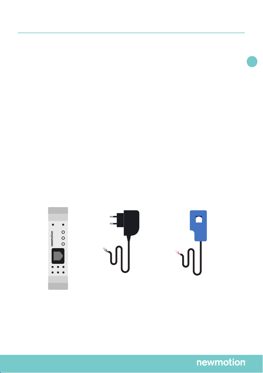
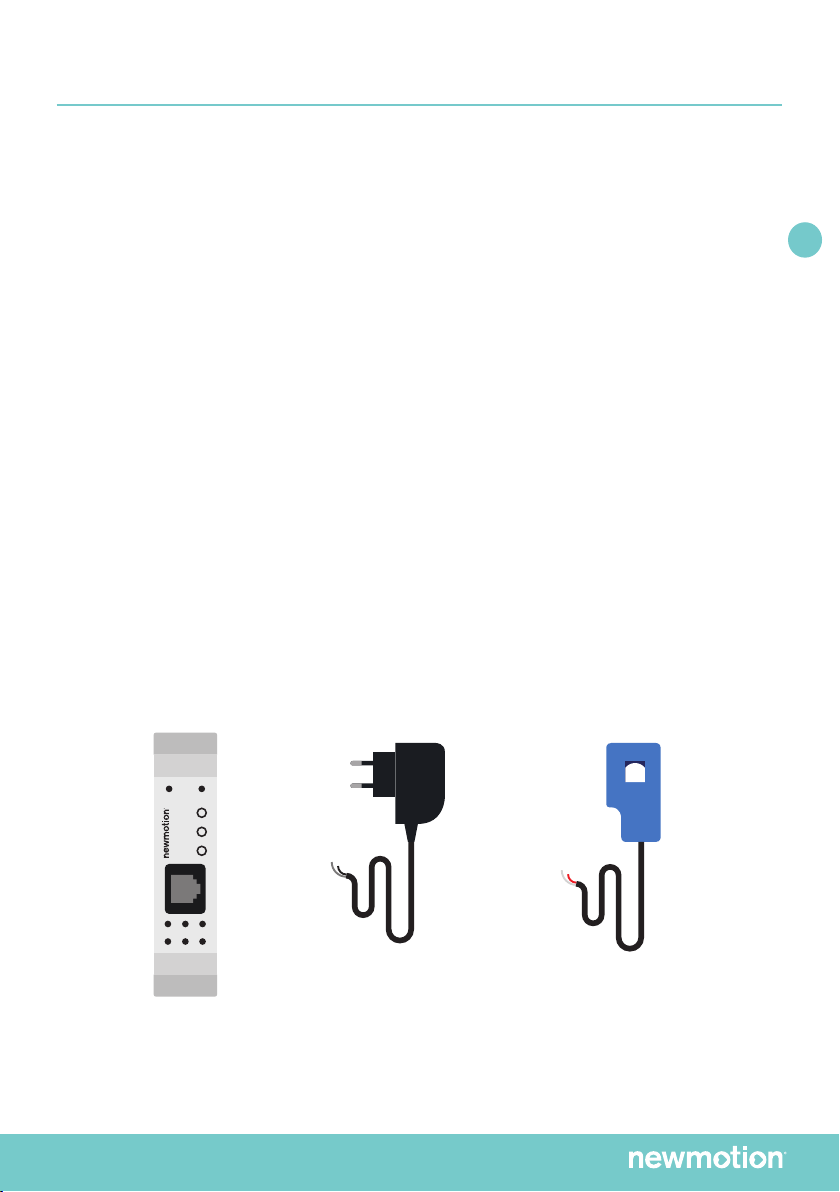
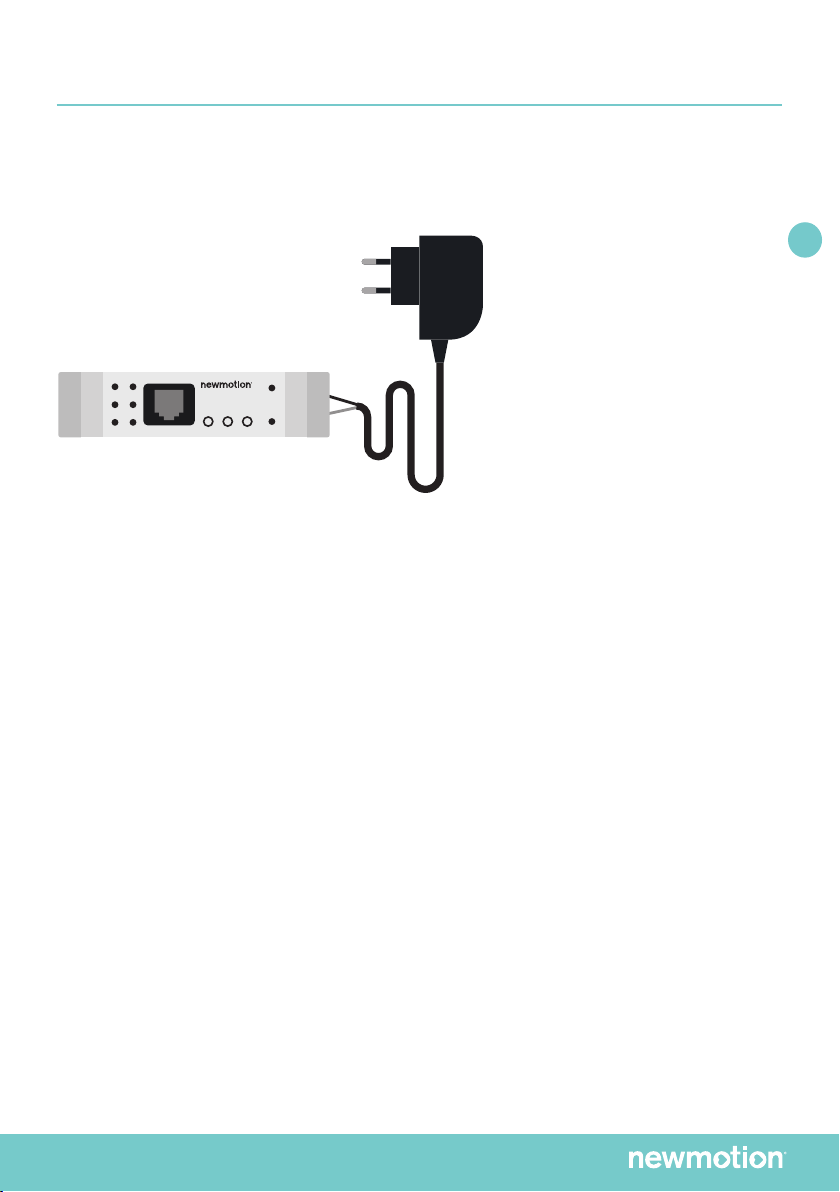
A. De P1-stroomsensormodule.
B. Een externe voedingsadapter van 5V DC. Met een kabellengte van 1,5 m.
C. 1 of 3 stroomtransformatoren, afhankelijk van het aantal fasen. Met een kabellengte van 1,0 m
COMPONENTEN
A.B.C.
+5V GND
STB
L1 L2 L3
CS
P1
+5V GND
STB
L1 L2 L3
CS
P1
+5V GND
STB
L1 L2 L3
CS
P1
+5V GND
STB
L1 L2 L3
CS
P1
+5V GND
STB
L1 L2 L3
CS
P1

P-4 | NEDERLANDS | X1NM19INT01
NL EN DE FR
INSTALLATIE
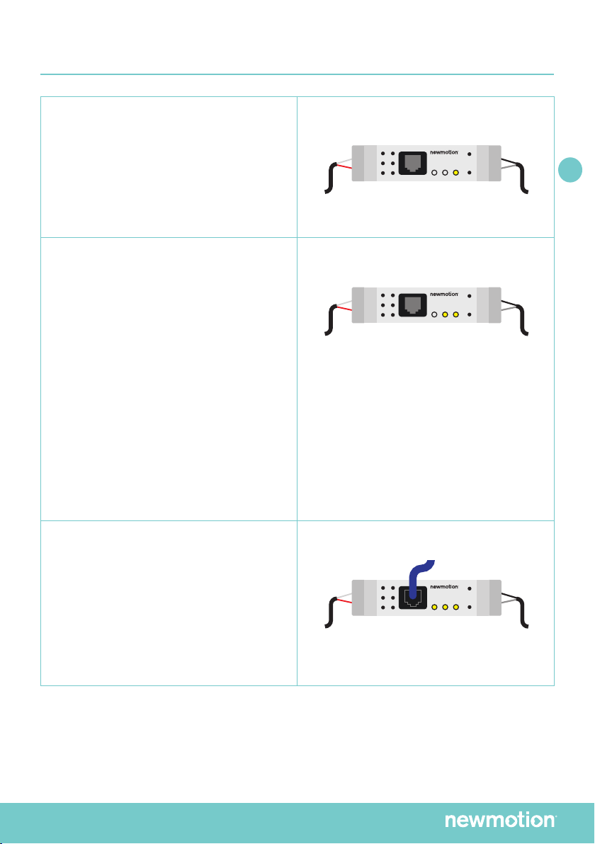
De stroomsensormodule moet worden aangesloten zoals is aangegeven
op het label op de voorzijde:
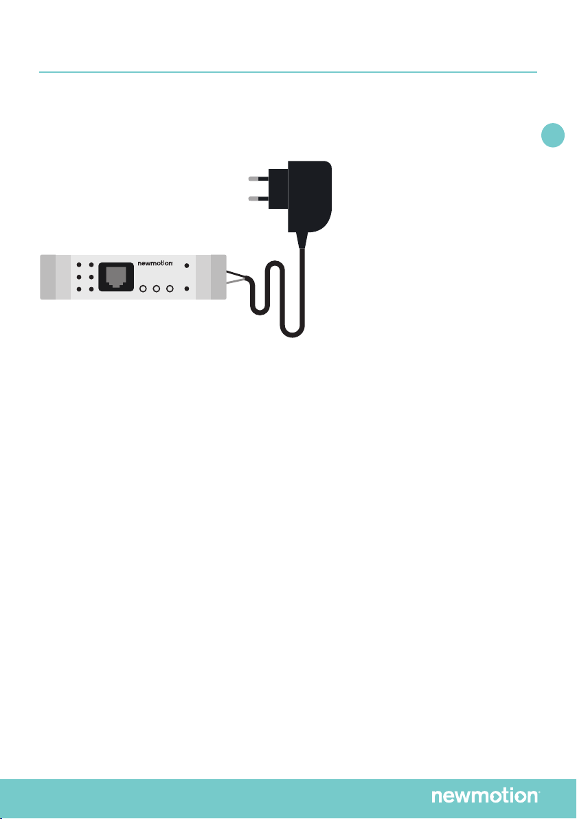
1. De externe voedingsadapter is aangesloten op de twee buitenste aansluitingen
bovenop de module.
Opmerking: Polariteit is belangrijk! 1 van de 2 draden van de voedingsadapter heeft een gebroken
witte streep. Deze draad is de GND (aardaansluiting) van de voedingsadapter en moet daarom worden
aangesloten op de GND-pin (rechts) van de module. De andere draad is de +5 V-draad en moet
worden aangesloten op de +5 V-pin (links) van de module. De pin in het midden wordt niet gebruikt.
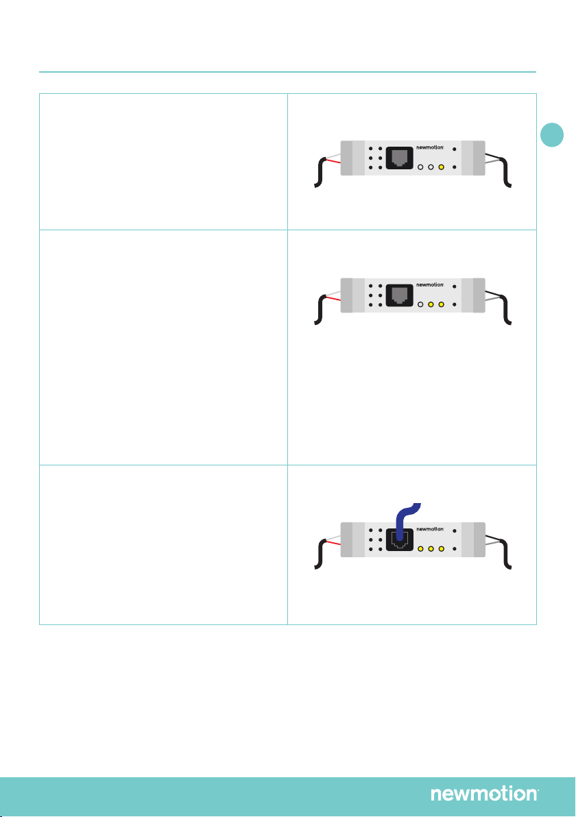
2. De stroomtransformatoren (CT): Er kunnen maximaal 3 CT-koppen worden aangesloten
op de module. De verbindingen bevinden zich aan de onderkant van de module en zijn
aangemerkt met L1, L2 en L3 op het label aan de voorkant. Iedere CT-draad kan boven
een andere worden gemonteerd. Hoewel iedere meetkop is voorzien van 2 verschillend
gekleurde draden, is de polariteit niet van belang bij het aansluiten.
3. De CT’s die zijn verbonden met L1, L2 en L3 moeten in de correcte volgorde worden
aangesloten op de eerste, tweede en derde fase van het elektriciteitsnet van het huis.
Er staan pijlen op de CT, maar de richting is niet belangrijk.
4. De stroomkabel aansluitingen op het klemmenblok van het laadpunt dient overeen te
komen met de L1, L2 en L3 van de module. Voor een 1 fase installatie dient de L1 CT
op dezelfde fase geleider te zitten als die is aangesloten op het klemmenblok.
+5V GND
STB
L1 L2 L3
CS
P1
+5V GND
STB
L1 L2 L3
CS
P1
+5V GND
STB
L1 L2 L3
CS
P1
+5V GND
STB
L1 L2 L3
CS
P1
+5V GND
STB
L1 L2 L3
CS
P1

P-5 | NEDERLANDS | X1NM19INT01
NL EN DE FR
INSTALLATIE
INSTALLATIEPROCEDURE
Let op: zet de module en laadpaal niet op spanning tijdens de installatie.
Volg de onderstaande stappen voor installatie:
1. Sluit de voedingsadapter nog niet aan op het stopcontact.
2. Sluit de voedingsadapter aan op de P1-stroomsensormodule.
3. Sluit de CT(‘s) aan op de P1-stroomsensormodule.
4. Bevestig de P1-stroomsensormodule op de DIN-rail in de stoppenkast.
5. Sluit de CT(‘s) aan op de netaansluiting(en). Sluit de CT(‘s) zodanig aan dat het totale
stroomverbruik per fase wordt gemeten.
6. Sluit de voedingsadapter aan op een stopcontact. De PWR-LED moet gaan branden.
7. Indien de stroom is ingeschakeld, geeft de CS-LED (na een paar seconden) een
gemeten stroom aan.
8. Leg de kabel aan tussen het laadpunt en de DPM module. De maximale lengte van de
kabel tussen het laadpunt en de DPM module is 20 meter.
• Home Advanced 2.1: dienen de aansluitingen van de RJ12- kabel
6 aderig straight te worden verbonden.
• Home Advanced 2.0: de aansluitingen van de RJ-12 kabel dienen kruislings
(cross) te worden verbonden.
9. Sluit de RJ12 (6P6C)-kabel aan op de module. Als het andere uiteinde van de kabel al is
aangesloten op het laadpunt, geeft de P1-LED aan of dit correct is gebeurd.
10. Neem contact op met NewMotion voor activering van DLB-H op afstand:
+31 (0)88 010 9500
Opmerking 1: De P1-interface wordt 10 seconden na het opstarten geactiveerd.
Gedurende deze periode worden er geen P1-berichten verzonden en zal de P1-LED niet oplichten.

P-6 | NEDERLANDS | X1NM19INT01
NL EN DE FR
LED-FUNCTIONALITEIT
PWR-LED
De PWR-LED zal oplichten vanaf het
moment dat het apparaat wordt voorzien
van stroom. Als de LED niet oplicht, is het
raadzaam om eerst te controleren of er iets
mis is met de stroomvoorziening en of de
voedingsadapter correct is aangesloten.
Als het totaal van de stroom in L1, L2 en L3
bijvoorbeeld 10 A is, zal deze LED iedere
seconde 200 ms oplichten en gedurende
800 ms zijn uitgeschakeld. Als de totale
stroom meer is dan 50 A zal de LED
continu branden.De installateur kan deze
LED gebruiken om te controleren of stroom
wordt gemeten.
CS-LED
De stroomsensor-LED geeft weer hoeveel
actuele stroom er wordt gemeten van het
totaal. De LED knippert met intervallen van
1 seconde. Hierbij knippert de LED 20 ms
per ampère gecumuleerde stroom.
P1-LED
De P1-LED gaat branden zodra de
communicatie met een P1-apparaat
wordt geactiveerd. Voor een werkende
communicatie moet de module via een
RJ12-kabel zijn verbonden met een
NewMotion Home Advanced-oplaadpunt
met een actieve P1-functionaliteit.
+5V GND
STB
L1 L2 L3
CS
P1
+5V GND
STB
L1 L2 L3
CS
P1
+5V GND
STB
L1 L2 L3
CS
P1
+5V GND
STB
L1 L2 L3
CS
P1
+5V GND
STB
L1 L2 L3
CS
P1
+5V GND
STB
L1 L2 L3
CS
P1
+5V GND
STB
L1 L2 L3
CS
P1
+5V GND
STB
L1 L2 L3
CS
P1
+5V GND
STB
L1 L2 L3
CS
P1
+5V GND
STB
L1 L2 L3
CS
P1
+5V GND
STB
L1 L2 L3
CS
P1
+5V GND
STB
L1 L2 L3
CS
P1
+5V GND
STB
L1 L2 L3
CS
P1
+5V GND
STB
L1 L2 L3
CS
P1
+5V GND
STB
L1 L2 L3
CS
P1
P-7 | ENGLISH | X1NM19INT01
NL EN DE FR
INTRODUCTION
The Dynamic Power Management Home - Module is required for the service ‘Dynamic
Power Management’ for home locations. The module measures the current on each phase
of the household. Messages with the real time total power consumption are sent from the
module to the charge point via a UTP cable. With this information the charge point will
calculate the capacity which is available for charging a car.
Up to 3 measurement heads can be connected to the device. These measuring heads
are Current Transformers (CTs), and can be installed around a current conductor without
disturbing the installation. In a three phase installation the CTs should be attached to L1, L2
and L3. In case of a one phase installation or grid connection without neutral, only attach
one CT to the current conductor which is attached to L1 in the chargepoint.
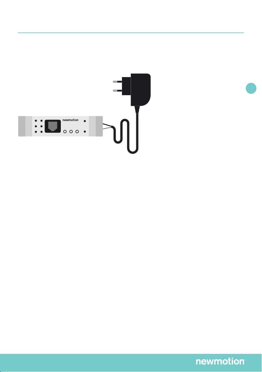
A. The P1 current sense module.
B. An external 5VDC power adapter. With a cable length of 1.5m.
C. 1 or 3 current transformers, depending on amount of phases. With a cable length of 1.0m.
COMPONENTS
A.B.C.
+5V GND
STB
L1 L2 L3
CS
P1
+5V GND
STB
L1 L2 L3
CS
P1
+5V GND
STB
L1 L2 L3
CS
P1
+5V GND
STB
L1 L2 L3
CS
P1
+5V GND
STB
L1 L2 L3
CS
P1
P-8 | ENGLISH | X1NM19INT01
NL EN DE FR
+5V GND
STB
L1 L2 L3
CS
P1
+5V GND
STB
L1 L2 L3
CS
P1
+5V GND
STB
L1 L2 L3
CS
P1
+5V GND
STB
L1 L2 L3
CS
P1
+5V GND
STB
L1 L2 L3
CS
P1
INSTALLING
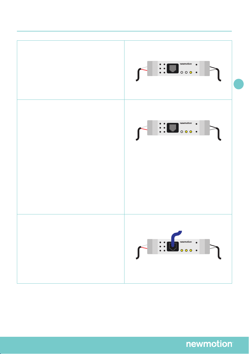
The current sensor module must be connected as indicated on the front label:
1. The external power adapter is connected to the two outer terminals on the top
of the module.
Note: Polarity is important! 1 of the 2 power adapter wires has a broken white stripe. This wire is the power
adapter GND and should therefore be connected to the GND pin (right) on the module. The other wire is the
+5 Volts and should be connected to the +5V pin (left) on the module. The middle pin is not used.
2. The current transformers (CT): Up to 3 CT heads can be connected to the module.
The connections are located at the bottom of the module, and are labelled with
L1, L2 and L3 on the front label. Each CT wire can be mounted one above the other.
Althougheachmeasuringheadisprovidedwith2differentcolouredthreads,
the polarity of connection is not important.
3. TheCT’sconnectedtoL1,L2andL3mustbeconnectedtotherst,secondandthird
phase of the house grid in the correct order. Arrows are shown on the CT, but direction
is not important.
4. The powercable connection on the terminal block of the chargepoint should match the
L1, L2 and L3 of the module. For a 1 phase installed chargepoint the L1 measurement
head should match the conductor which is connected to the L1 of
the terminal block.

P-9 | ENGLISH | X1NM19INT01
NL EN DE FR
INSTALLING
INSTALLATION PROCEDURE
Warning: keep module and charge point switched o during installation.
To complete an installation, proceed as follows:
1. Don’t plug the power adapter in the power outlet yet.
2. Connect the power adapter to the P1 current sense module.
3. Connect the CT(s) to the P1 current sense module.
4. Install the P1 current sense module on the DIN Rail in the fuse box.
5. Apply the CT(s) to the grid connection(s). Make sure to apply the CT(s) so that the total
power usage per phase is measured.
6. Plug the power adapter into a power outlet. The PWR LED must light up.
7. The CS LED will (after a few seconds) indicate a measured current after the power is on.
8. Prepare the cable between chargepoint and DPM module. The maximum length of the
cable between charge point and DPM module is 20 meters.
• Home Advanced 2.1: the connectors should be attached straight wired with 6
wires and a RJ-12 connector.
• Home Advanced 2.0: the connectors should be attached cross wired.
9. Connect the RJ12 (6P6C) cable to the module. If the other end of the cable is already
connected to the charge point, the P1 LED will indicate whether the connection is
correct.
10. Contact New Motion for remote activation of DPM on number +44 (0)203 868 1036
Note 1: The P1 interface will be turned on 10 seconds after power up. During this period,
no P1 messages are sent and the P1 LED will not light up.
P-10 | ENGLISH | X1NM19INT01
NL EN DE FR
FUNCTIONALITY LED
PWR LED
The Power LED will light up from the
moment the device is put on power. If the
LEDdoesn’tlightup,itisadvisabletorst
check the power supply and if the power
adapter is connected correctly.
E.G. if the sum of the currents by L1, L2 and
L3 is 10A, then this LED will lit 200ms every
second,andwillbeoff800ms.Fromatotal
current >= 50A, the LED will be continuously
lit. To check if a current is being measured
the installer can use this LED.
CS LED
The current sense LED displays the actual
current measured of the total power. The
LEDwillashwithaperiodof1second.
HerebytheLEDwillash20msper
Ampere cumulated current.
P1 LED
The P1 LED will light up as soon as the
communication with a P1 device becomes
active. For a working connection
the module needs to connected to a
NewMotion Home Advanced charge point
with an active P1 functionality, via an UTP
cable with RJ12 connectors.
+5V GND
STB
L1 L2 L3
CS
P1
+5V GND
STB
L1 L2 L3
CS
P1
+5V GND
STB
L1 L2 L3
CS
P1
+5V GND
STB
L1 L2 L3
CS
P1
+5V GND
STB
L1 L2 L3
CS
P1
+5V GND
STB
L1 L2 L3
CS
P1
+5V GND
STB
L1 L2 L3
CS
P1
+5V GND
STB
L1 L2 L3
CS
P1
+5V GND
STB
L1 L2 L3
CS
P1
+5V GND
STB
L1 L2 L3
CS
P1
+5V GND
STB
L1 L2 L3
CS
P1
+5V GND
STB
L1 L2 L3
CS
P1
+5V GND
STB
L1 L2 L3
CS
P1
+5V GND
STB
L1 L2 L3
CS
P1
+5V GND
STB
L1 L2 L3
CS
P1
P-11 | DEUTSCH | X1NM19INT01
NL EN DE FR
EINFÜHRUNG
Für dynamischen Lastausgleich an einer Heim-Ladestation ist das Home-Modul erforderlich.
Das Modul misst die Spannung(en) und überträgt die Werte in eine Meldung. Das Modul kann
nur zusammen mit der Ladestationen des Typs NewMotion Home Advanced benutzt werden.
Das Modul übermittelt mittels einer Reihe von Meldungen den gesamten Stromverbrauch der
Hausanlage in Echtzeit. Auf der Grundlage dieser Informationen berechnet die Ladestation
dann die verfügbare Stromkapazität für die einzelnen Ladevorgänge.
Bis zu 3 blaue Messköpfe können an das Gerät angeschlossen werden. Diese Messköpfe
sind Stromwandler und können an einem Stromleiter installiert werden, ohne dass die
Leitungen getrennt und neu verbunden werden müssen. In einer 3-Phasigen-Installation,
müssen L1, L2 und L3 mit dem Stromwandler verbunden werden. Im Falle einer 1-Phasigen-
Installation oder in Netzen ohne Neutralleiter, muss der Stromwandler an den Stromleiter
angeschlossen werden, welcher in L1 mit der Ladestation verbunden ist.
A. Das P1-Stromsensor-Modul.
B. Ein externes 5V-GS-Netzteil. Kabellänge 1,5 m.
C. 1 oder 3 Stromwandler, je nach Anzahl der Phasen. Kabellänge 1,0 m.
KOMPONENTEN
A.B.C.
+5V GND
STB
L1 L2 L3
CS
P1
+5V GND
STB
L1 L2 L3
CS
P1
+5V GND
STB
L1 L2 L3
CS
P1
+5V GND
STB
L1 L2 L3
CS
P1
+5V GND
STB
L1 L2 L3
CS
P1
P-12 | DEUTSCH | X1NM19INT01
NL EN DE FR
INSTALLATION
Das Stromsensor-Modul ist wie auf dem Etikett an der Vorderseite angegeben anzuschließen:
1. Das externe Netzteil wird mit den beiden äußeren Anschlüssen an der Oberseite des
Moduls verbunden.
Hinweis: Beachten Sie die Polarität! Eines der beiden Netzteilkabel hat eine gestrichelte weiße Linie.
Das ist das Massekabel des Netzteils und muss daher mit dem Masse-Stecker (rechts) des Moduls
verbunden werden. Das andere Kabel ist das +5-V-Kabel und wird mit dem +5-V-Pin (links) am Modul
verbunden. Der mittlere Stecker ist nicht belegt.
2. Die Stromwandler: Bis zu 3 Stromwandler- Messköpfe können an das Gerät
angeschlossen werden. Die Anschlüsse an der Unterseite des Moduls sind am Etikett
auf der Vorderseite als L1, L2 und L3 gekennzeichnet. Die Stromwandlerkabel können
übereinander angebracht werden. Die Messköpfe haben zwar Anschlüsse in zwei
verschiedenen Farben, doch die Polarität der Verbindung spielt keine Rolle.
3. Die Stromwandler an L1, L2 und L3 müssen in der richtigen Reihenfolge an
die erste, zweite und dritte Phase des Hausstromkreises angeschlossen werden.
Die Richtungspfeile auf den Stromwandlern spielen keine Rolle.
4. Die Stromwandler an L1, L2 und L3 müssen in der richtigen Reihenfolge an die erste,
zweite und dritte Phase des Hausstromkreises angeschlossen werden. Bei einer
einphasigen Installation der Ladesäule sollte der L1-Messkopf mit der, zum L1 des
Anschlussblocks verbundenen Leitung, übereinstimmen.
+5V GND
STB
L1 L2 L3
CS
P1
+5V GND
STB
L1 L2 L3
CS
P1
+5V GND
STB
L1 L2 L3
CS
P1
+5V GND
STB
L1 L2 L3
CS
P1
+5V GND
STB
L1 L2 L3
CS
P1

P-13 | DEUTSCH | X1NM19INT01
NL EN DE FR
INSTALLATION
INSTALLATIONSVERFAHREN
Warnung: Modul und Ladestation bei der Installation ausschalten.
Führen Sie die Installation wie folgt durch:
1. Schließen Sie das Netzteil noch nicht an die Steckdose an.
2. Verbinden Sie das Netzteil mit dem P1-Stromsensor-Modul.
3. Verbinden Sie den/die Stromwandler mit dem P1-Stromsensor-Modul.
4. Installieren Sie das P1-Stromsensor-Modul auf der DIN-Schiene im Sicherungskasten.
5. Verbinden Sie den/die Stromwandler mit dem Netzstromanschluss/den
Netzstromanschlüssen. Achten Sie beim Anbringen des Stromwandlers/der
Stromwandler darauf, dass der Gesamtstromverbrauch der Phase gemessen wird.
6. SchließenSiedasNetzteilaneineSteckdosean.DiePWR-LEDsolltenunaueuchten.
7. Die Stromsensor (CS)-LED zeigt (nach einigen Sekunden) die Strommessung an.
8. Bei der Kabelverlegung zwischen der Ladesäule und dem DPM-Modul ist das Folgende
zu beachten: die maximale Kabellänge zwischen der Ladesäule und dem DPM-Modul
beträgt 20 m.
• Home Advanced 2.1: die Anschlüsse sollten gerade RJ-12 (6P6C) verbunden
werden.
• Home Advanced 2.0: die Anschlüsse sollten durch Querverdrahtung verbunden
werden.
9. Verbinden Sie das RJ12-Kabel mit dem Modul. Wenn das andere Ende des Kabels
bereits an die Ladestation angeschlossen ist, sehen Sie anhand der P1-LED, ob die
Verbindung ordnungsgemäß hergestellt ist.
10. Kontaktieren Sie New Motion unter der Nummer +49 (0)30 215 028 48, um die DPM-H
Ferneinschaltung durchzuführen.
Hinweis 1: Die P1-Schnittstelle wird 10 Sekunden nach dem Einschalten aktiviert.
Während dieses Zeitraums werden keine P1-Meldungen übertragen, und die P1-LED leuchtet nicht.
P-14 | DEUTSCH | X1NM19INT01
NL EN DE FR
FUNKTIONS-LED
PWR-LED
Die Power-LED leuchtet auf, sobald
Sie das Gerät an die Stromversorgung
anschließen. Wenn die LED nicht leuchtet,
prüfen Sie zunächst die Verbindungen zum
und vom Netzteil.
Wenn Sie Summe der Spannung an L1,
L2 und L3 beispielsweise 10 A beträgt,
leuchtet diese LED 200 ms pro Sekunde
und bleibt 800 ms lang aus. Ab einer
Gesamtspannung von >= 50 A leuchtet die
LED durchgehend. Der Installateur kann
an dieser LED erkennen, ob Spannung
gemessen wird.
CS-LED
Die Stromsensor (CS)-LED zeigt den
aktuellen Messwert der Gesamtleistung.
Die LED blinkt im Sekundentakt. Dabei
leuchtet sie 20 ms pro Ampere kumulierte
Leistung.
P1-LED
Die P1-LED leuchtet auf, sobald
Kommunikation mit einem P1-Gerät
besteht. Voraussetzung für diese
Kommunikation ist die Verbindung des
Moduls über ein RJ12-Kabel mit einer
Ladestation des Typs NewMotion Home
Advanced mit aktiver P1-Funktion.
+5V GND
STB
L1 L2 L3
CS
P1
+5V GND
STB
L1 L2 L3
CS
P1
+5V GND
STB
L1 L2 L3
CS
P1
+5V GND
STB
L1 L2 L3
CS
P1
+5V GND
STB
L1 L2 L3
CS
P1
+5V GND
STB
L1 L2 L3
CS
P1
+5V GND
STB
L1 L2 L3
CS
P1
+5V GND
STB
L1 L2 L3
CS
P1
+5V GND
STB
L1 L2 L3
CS
P1
+5V GND
STB
L1 L2 L3
CS
P1
+5V GND
STB
L1 L2 L3
CS
P1
+5V GND
STB
L1 L2 L3
CS
P1
+5V GND
STB
L1 L2 L3
CS
P1
+5V GND
STB
L1 L2 L3
CS
P1
+5V GND
STB
L1 L2 L3
CS
P1

P-15 | FRANÇAIS | X1NM19INT01
NL EN DE FR
INTRODUCTION
And’éviterdemodiersonabonnementdefournitured’énergieetd’offrirunéquilibragede
charge dynamique à domicile, le module Dynamic Power Management Home est requis.
Le module mesure le(s) courant(s) et traduit les valeurs dans un message pour le borne de
recharge.LemodulepeutêtreinstalléuniquementavecunebornederechargeNewMotion
Home Advanced. Le module envoie un signal pour indiquer la consommation totale
d’énergieentempsréeld’uneinstallation.Aveccetteinformation,labornevacalculer
la puissance disponible pour recharger une voiture.
Cetaccessoireuniverselpeutêtremisenplacesuruneinstallationélectriquemonophasée
outriphaséeàl’aidedestransformateursdecourantfournis(TC).Cestransformateurs
decourant(TC)peuventêtreinstalléesautourd’unconducteurdecourantsansmettre
horstensionl’installation(sanscâblageàdébrancher).Letransformateurdecourant
doitêtreinstallésurL1pouruneinstallationmonophaséeousurL1,L2etL3pour
uneinstallationtriphasée.
A. Module de mesure de courant P1.
B. Adaptateur d’alimentation externe 5VDC, avec câble de 1,5 m.
C. 1 ou 3 transformateurs de courant, selon le nombre de phases, avec câble de 1 m.
COMPOSANTS
A.B.C.
+5V GND
STB
L1 L2 L3
CS
P1
+5V GND
STB
L1 L2 L3
CS
P1
+5V GND
STB
L1 L2 L3
CS
P1
+5V GND
STB
L1 L2 L3
CS
P1
+5V GND
STB
L1 L2 L3
CS
P1
P-16 | FRANÇAIS | X1NM19INT01
NL EN DE FR
INSTALLATION
Le module de mesure de courant doit être alimenté comme indiqué sur l’étiquette frontale :
1. L’adaptateurd’alimentationexterneestconnectéàdeuxbornesextérieures
sur le haut du module.
Remarque : Lapolaritéestimportante!1des2lsd’adaptateurd’alimentationaunerayureblanche.
Lelrayéblancdel’adaptateurd’alimentationdoitêtreconnectéàlabornedeterre(GND)surle
module.Lelnoirdeestl’adaptateurd’alimentationdeterreetdoitdoncêtreconnectéàlaborne+5V
surlemodule.Lebornierdumilieun’estpasutilisée.
2. Transformateursdecourant(TC):Jusqu’àtroisTCpeuventêtreconnectésaumodule.
Lesconnexionssetrouventendessousdumodule,etsontétiquetéesL1,L2
etL3surl’étiquettefrontale.ChaquelTCpeutêtremontél’unau-dessusdel’autre.
Bienquechaquetêtedemesuresoitfournieavec2lsdecouleursdifférentes,
lapolaritédelaconnexionn’estpasimportante.
3. LesTCconnectésàlaborneL1(respectivementL2etL3)doiventêtreconnectés
àlaphase1delamaison(respectivementL2etL3).Desèchessontaffichées
sur le TC, mais la direction n’est pas importante.
+5V GND
STB
L1 L2 L3
CS
P1
+5V GND
STB
L1 L2 L3
CS
P1
+5V GND
STB
L1 L2 L3
CS
P1
+5V GND
STB
L1 L2 L3
CS
P1
+5V GND
STB
L1 L2 L3
CS
P1

P-17 | FRANÇAIS | X1NM19INT01
NL EN DE FR
INSTALLATION
PROCÉDURE D’INSTALLATION
Avertissement : eectuez l’installation du module et borne hors tension.
Pour réaliser l’installation, procédez comme suit :
1. Ne branchez pas tout de suite l’adaptateur d’alimentation sur secteur.
2. Connectez l’adaptateur d’alimentation sur le module de mesure de courant P1.
3. Branchez le(s) TC sur le module de mesure de courant P1.
4. InstallezlemoduledemesuredecourantP1surlerailDINdansletableauélectrique.
5. Placezle(s)TCsurlesphasesdel’installationélectrique.Assurez-vousd’appliquerle(s)
TCdemanièreàcequelaconsommationélectriquetotaled’unephasesoitmesurée.
6. Mettez le module de mesure de courant P1 sous tension en branchant l’adaptateur
d’alimentation sur secteur. La LED power (PWR) s’allume.
7. Aprèsquelquessecondes,laLEDCSindiquelecourantmesuré.
8. Preparez le câble entre la borne et le module de DPM. La longueur maximum du câble
entre la borne et le module DPM est de 20 mètres.
• HomeAdvanced2.1:lesconnecteursdoiventêtreattachésdirectementaux6ls
et un connecteur RJ-12.
• HomeAdvanced2.0:lesconnecteursdoiventêtreattachésentre-croisés.
9. ConnectezlecâbleRJ12(6P6C)aumodule.Sil’autrecôtéducâbleestdéjàconnectéà
la borne, la LED P1 indiquera si la connexion est correcte ou non.
10. Merci de bien vouloir contacter NewMotion pour l’activation à distance du DPM au
numéro+33975180355
Remarque 1 : L’interfaceP1s’allume10secondesaprèslamisesoustension.Durantcettepériode,
aucunmessageP1n’estenvoyé,etlaLEDP1nes’allumepas.
P-18 | FRANÇAIS | X1NM19INT01
NL EN DE FR
FONCTIONNALITÉ DES LED
LED PWR
La LED PWR s’allume à partir du moment
où l’appareil est mis sous tension. Si la
LEDnes’allumepas,ilestrecommandé
devérierd’abordl’alimentationélectrique,
et que l’adaptateur d’alimentation est
correctementbranché.
Par exemple, si la somme des courants L1,
L2 et L3 est de 10 A, alors cette LED s’allume
200msparseconde,ets’éteint800mspar
seconde. À partir d’un courant total >=50 A,
laLEDrestecontinuellementallumée.
Pourvérierqu’uncourantestbienen
cours de mesure, l’installateur peut utiliser
cette LED.
LED CS
LaLEDdedétectiondecourantCSaffiche
lecourantréelmesurédel’électricitétotale.
La LED clignote chaque seconde. La LED
clignote 20 ms par ampère de courant
cumulé.
LED P1
La LED P1 s’allume dès que la
communication avec un appareil P1 devient
active. Pour obtenir une communication
fonctionnelle, le module doit être connecté
à la borne de recharge NewMotion Home
Advanced avec une fonctionnalité P1
active, via un câble RJ12.
+5V GND
STB
L1 L2 L3
CS
P1
+5V GND
STB
L1 L2 L3
CS
P1
+5V GND
STB
L1 L2 L3
CS
P1
+5V GND
STB
L1 L2 L3
CS
P1
+5V GND
STB
L1 L2 L3
CS
P1
+5V GND
STB
L1 L2 L3
CS
P1
+5V GND
STB
L1 L2 L3
CS
P1
+5V GND
STB
L1 L2 L3
CS
P1
+5V GND
STB
L1 L2 L3
CS
P1
+5V GND
STB
L1 L2 L3
CS
P1
+5V GND
STB
L1 L2 L3
CS
P1
+5V GND
STB
L1 L2 L3
CS
P1
+5V GND
STB
L1 L2 L3
CS
P1
+5V GND
STB
L1 L2 L3
CS
P1
+5V GND
STB
L1 L2 L3
CS
P1


Table of contents
Languages:
Other newmotion Automobile Accessories manuals


Popular Automobile Accessories manuals by other brands


Fast
Fast 307500 instructions

Kolpin Outdoors
Kolpin Outdoors Polaris Ranger 570-6 / 800 Product instructions

Horizon Global
Horizon Global 118884 installation instructions

Energizer
Energizer ENC100 owner's guide

Fabtech
Fabtech FTS7006 installation instructions

Rhino-Rack
Rhino-Rack 43180B Fitting instructions


