manuals.online logo
Brands
  1. Home
  2. •
  3. Brands
  4. •
  5. Newport
  6. •
  7. Measuring Instrument
  8. •
  9. Newport N-STP-910 User manual

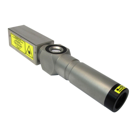
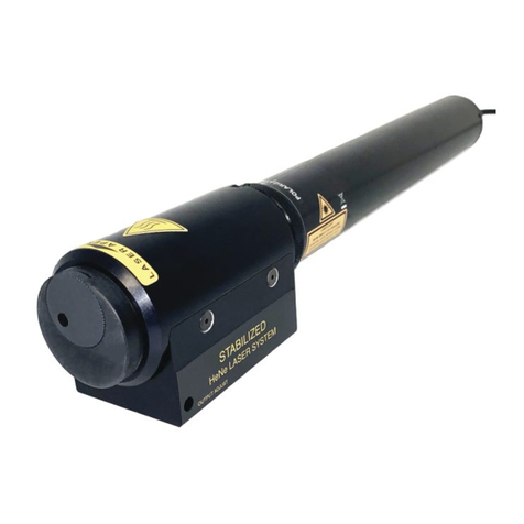
Newport N-STP-910 User manual

1791 Deere Avenue
Irvine, California
920606 USA
www.newport.com/contact-us
______________________________________________________________________________________
+1 949-863-3144 | Newport Corporation | www.newport.com
Single Frequency Laser
Operating Manual
Models N-STP-910, N-STP-912
L10698-1 REV: 03.20.2 NPT
NOTICE: This manual contains specifications, descriptions, and drawings for the Newport stabilized
Helium Neon laser systems.
Product specifications contained in this manual are subject to change without prior notice. Newport
Corporation will not be responsible for errors or omissions in this manual, or for incidental or
consequential damages in connection with the furnishing or use of this information.
This document may not be photocopied, duplicated, or reproduced by any means without the prior
written consent of Newport Corporation.
Comments or suggestions regarding this manual are appreciated and should be sent to the following
address:
Newport Corporation
1791 Deere Avenue
Irvine, California, 92606 USA
Attention: Customer Service
Phone (949) 863-3144
www.newport.com/contact-us
Publication date: March 12, 2020
©2020 Newport Corporation
+1 949-863-3144 | Newport Corporation | www.newport.com
Model N-STP Operation Manual Introduction
1.1. Laser Safety and Precautions
Never look directly into the beam of the laser system.
One of two labels (a caution label or a danger label) is attached to the standard laser head to warn operators of the
potential hazards. These labels are illustrated in Figure 1-1.
Figure 1-1. Standard Caution and Shipping Labels
1-3
Introduction In This Section:
•Laser Safety and Precautions............................................1-3
•Installation Instructions.....................................................1-4
•Operating Instructions.......................................................1-5
•Preventative Maintenance.................................................1-10
•Troubleshooting................................................................1-11
LASER LIGHT
DO NOT STARE INTO BEAM
CLASS II LASER PRODUCT (CDRH)
CLASS 2 LASER PRODUCT (IEC 60825-1:2007)
1mw MAXIMUM AT 632.8nm
LASER LIGHT
AVOID EXPOSURE TO BEAM
CLASS IIIa LASER PRODUCT (CDRH)
CLASS 3R LASER PRODUCT (IEC 60825-1:2007)
5mw MAXIMUM AT 632.8nm
COMPLIES WITH CDRH 21 CFR
1040.10 AND IEC 60825-1:2007
COMPLIES WITH CDRH 21 CFR
1040.10 AND IEC 60825-1:2007
N-STP-910
N-STP-912
Introduction Model N-STP Operation Manual
1.1.1. CDRH Regulations
The N-STP series laser systems are CDRH certified according to the rules and regulations as outlined in
part III of the Department of Health and Human Services, 21 CFR Parts 1000 and 1040 for laser products.
Under these guidelines, the Model N-STP-912 conforms to CLASS IIIa (IEC 3R) certification, which allows
maximum output power of up to 5mW continuous radiation at a visible wavelength of 633nm. The Model
N-STP-910 conforms to CLASS II (IEC 2), which allows maximum output power of up to 1mW. Other
requirements include the use of special labeling, an external mechanical beam attenuator, and a pilot light
indication during operation.
The N-STP laser system is shipped from the factory with the necessary features to conform with the above
regulations. These features are recorded for each individual unit and reported per CDRH regulations under
the Accession number 9320815. Assistance is provided for customers in their product designs to ensure
maximum safety and compliance with CDRH regulations. Detailed information on these requirements may
be obtained at: www.fda.gov/radiation-emitting-products/
1.1.2. Power Source and Grounding
The N-STP series laser system include either the laser head (N-STP-910 and N-STP-912) attached to the
single frequency adapter (SFA). They are supplied with the appropriate AC/DC converters and power
supplies for the line voltage requested. Both the AC/DC converters and power supplies are supplied with
grounding connections so the laser head and adapter housing are grounded when they are plugged into the
appropriate wall outlet.
Under no condition should the ground be defeated.
Verify the power common is at ground potential.
1.2. Installation Instructions
Do not energize system before reading the following sections
1-4
IMPORTANT
WARNING
Model N-STP Operation Manual Introduction
1.2.1. Initial Inspection
Check the contents of the shipping container for any signs of damage that may have occurred
during transportation. If the contents are damaged, a claim should be filed immediately with the
carrier and the Newport sales or customer service department in order to facilitate the repair
or replacement.
1.2.2. Grounding
Before operating the laser system, the system must be connected to a protective earth ground
conductor via the three-prong plug. The plug must be inserted into an outlet containing a
protective earth contact.
Any interruption of the earth ground may cause the laser housing to develop potentially high
voltages.
1.2.3. Operating environment
The N-STP frequency stabilized laser system may be safely operated in any orientation.
However, operation should be discontinued if condensation forms on any part of the system.
This is likely to occur when the system is brought from a cold to a warm environment.
Condensation may cause electrical shock if the housing is not properly grounded.
Even if proper grounding is provided, operation in the presence of condensation may cause
irreparable damage to the laser head.
1.3. Operating Instructions
1.3.1. Assembly and Switching On
The single frequency adapter (SFA) mates with the N-STP-910 and N-STP-912 laser heads. The
SFA and laser head are pre-assembled, calibrated and tested for optimum performance by and
should not be taken apart. The unit contains no user serviceable components. Disassembly of the
unit may result in exposure to laser light or hazardous voltages. Disassembly by an unauthorized
service center will void the warranty.
1-5
IMPORTANT
Introduction Model N-STP Operation Manual
The orientation of the laser head in relation to the SFA has been precisely adjusted and should
not be changed. The arrow on the laser head should align with the indent on the SFA (Figure 1-
2).
Figure 1-2. System Connections and Alignment
Connect and operate the system in the numerical order as shown in Figure 1-2. Connect the
main line voltage in accordance with Section 1.2.2.
Find and observe the output beam with a white card or piece of paper. The beam intensity should
noticeably increase and decrease in power initially at about once every two seconds and then at a
slower rate as the unit warms-up. For the N-STP-910, the minimum power will generally be zero.
Do not mistake this behavior for the laser turning off.
Application of power to the single frequency adapter (SFA) in excess of 5 minutes with the laser
head deenergized may damage the single frequency adapter.
The “Stable/OT” Green light should illuminate in approximately 5 to 10 minutes indicating that
the unit has reached operating temperature and has stabilized.
AC/DC Converters line voltages in excess of the nominal ratings will cause the system to warm-
up sooner, possibly resulting in a temporary loss of stabilization.
1-6
IMPORTANT
Model N-STP Operation Manual Introduction
1.3.2. Explanation of Controls and Indicators
1.3.2.1. AC/DC Converters
Each AC/DC Converter is supplied with an AC cord with proper grounding, along with an
ON/OFF switch and a visual indicator light indicating that 15 VDC is available at the male output
plug of the converter. The AC/DC converter can accommodate several ranges of frequency
(50Hz/60Hz) and voltages from 90 Volts to 265 Volts.
1.3.2.2. Stable (Green) Indicator
When the N-STP series laser system has attained proper operating temperature, the "Stable/OT"
light is energized (green) indicating that closed loop output control is in operation, see Figure 1-
4. The "Stable/OT" light may extinguish briefly under the following conditions:
•During the initial 20 minutes warm-up period.
•During ambient temperature changes beyond the 10C operating temperature range.
•Significant temperature changes to the laser head housing caused by mounting to a
large thermal inertia after the unit has been through the warm-up period.
•Excessive optical cavity feedback due to back reflections from optics in front of the
laser or outside instruments reflecting the beam back into the system.
Long term feedback resulting in the inability of the SFA to maintain closed loop operation
can result in laser and/or SFA failure.
1.3.2.3. OT (Red) Indicator
The same LED which energizes "green" indicating that the unit has reached stable operation may
energize "red" when the following conditions prevail:
•Power to laser head switched off with power applied to SFA.
•Failure of laser head to reach reference output power.
•Failure of single frequency control to close output control loop.
In any event, the "red" light indicates that the mirror mount has reached its maximum allowable
temperature limit and the energy to the induction coil has been shut down.
If this condition is not addressed, the SFA will safely cycle between the reset and maximum
temperature limit. This will be indicated by the LED changing between its "green" and "red"
indication.
1-7
IMPORTANT
Introduction Model N-STP Operation Manual
1.3.2.4. Output Adjust
A ten-turn potentiometer is accessible from the front right side of the adapter, see
Figure 1-4.
Adjustment should only be made with a plastic tuning screwdriver.
Full clockwise (CW) adjustment will increase the output power to typically 1.05mW
(N-STP-912), 0.7 to 0.9mW (N-STP-910), or within 400MHz of the center line frequency, see
Section 1.7. Full counter-clockwise (CCW) adjustment will decrease the output to typically
0.5mW for N-STP-912, to 0.35mW for N-STP-910, or to at least 600MHz from the "red side"
of the doppler curve, see Section 1.7. Each direction is torque protected so that over-turning
will result in no power change.
1.3.2.5. Principle of Operation
The N-STP single frequency laser system works on the principle that a Doppler Broadened
TEM00 output mode can be controlled in power and frequency if the cavity length (distance
between laser mirrors) can be controlled. In most single frequency lasers, heat conduction is
used (usually over the entire cavity length) to expand and thus control the cavity length. The
N-STP principle is unique in that it uses induction heating to control the length of a specially
designed mirror mount structure. In this way, a much smaller package can be accommodated.
More importantly, this technique allows for more rapid servo response Figure 1-3 depicts the
schematic block diagram of the induction servo control circuit.
1-8
IMPORTANT
Model N-STP Operation Manual Introduction
Model N-STP-910/912
SWITCHING
POWER SUPPLY
LASER TUBE
SFA ADAPTER
POLARIZER
BEAMSPLITTER
“p” & “s”
“p”
“p”
“s”
PIN DETECTOR
FEEDBACK AMP
A1
RF
AMP
MODULATOR
A2
+
-
OUTPUT ADJUST
ERROR AMP
IN
OUT
C
OPERATION
TEMPERATURE
DETECTOR
OVER
TEMPERATURE
SHUTDOWN
STABLE/OT
INDICATOR
GREEN
RED
Figure 1-3. Schematic Block Diagram
When the SFA is mated to the Models N-STP-910, or N-STP-912 laser head, the output beam
passes through two conditioning optics. The polarizer blocks the unwanted mode (“s”
component) while allowing the “p”component to pass at a very small attenuation. The
beamsplitter samples a portion of the “p”component for use as feedback to the control circuit.
Since the beamsplitter is also considerably polarization sensitive, this tandem arrangement
allows for very high polarization extinction (typically greater than 1000:1 at 1mW).
A high-quality PIN detector is used to convert the sampled “p”component into an electrical
current which is amplified by A1. A2 is a simple gain compensated error amplifier which
provides the necessary error signal to the modulator. The modulator in turn drives an RF
Amplifier which produces up to 10 watts to the mirror mount via the induction coil. The mirror
mount temperature, that is typically maintained at about 80C, is monitored by a temperature
detection circuit that controls the feedback signal to the error amplifier A2. When the mount
falls below a predetermined temperature, the feedback signal is removed from A2 causing full
power, causing cavity expansion. When the predetermined temperature is attained, (indicated
by a “green”LED) feedback is restored to A2 and the circuit locks in the single mode output.
An over-temperature shutdown circuit is configured to remove power to the mirror mount if for
some reason the output power control circuit fails to maintain closed loop control. When this
temperature limit is reached, a “red”LED indication occurs. 1-9
Introduction Model N-STP Operation Manual
1.3.3. Output Adjust and Operation Check
After the normal warm-up period, the output may be adjusted via the output adjust
potentiometer. Carefully adjust the screw full clockwise and note that the output power attains
at least 1mW (N-STP-912) or 0.80mW (N-STP-910). Next, adjust the screw full counter
clockwise verify the output power decreases to less than 0.70mW (N-STP-912) or 0.40mW
(N-STP-910). By adjusting the power over this range the absolute frequency is also adjusted.
In the case of the Model N-STP-912, this output frequency span corresponds to about 50 to
600MHz and for the N-STP-910, it corresponds to about 400 to 600MHz from center-line.
1. 4. Preventative Maintenance
The laser head and adapter should never be stored or operated in an environment having a high
concentration of airborne particulates. Exposure to this condition may cause interference with
the feedback to the PIN detector that can ultimately cause performance degradation or failure.
Periodic inspection of the SFA output optical surface is recommended.
The laser system must be turned off and disconnected from AC power.
The SFA output optical surface may be inspected by simply removing the shutter from the
SFA and looking through its aperture under a fluorescent light. The appearance of any foreign
matter is unacceptable. If it becomes necessary to clean the optical surface, the following
procedure should be used.
Using a clean cotton swab with reagent grade acetone or methanol. Gently clean the surface
of the beam splitter. Repeat the process twice to insure a clean surface.
Further service may be needed if a clean beam is not obtained.
Methanol is a toxic substance and should not be allowed to come in contact with
unprotected skin.
Internal optics assemblies can only be serviced by an authorized service center.
Refer to Figure 1-3 for the orientation of both optics in the adapter head.
1-10
IMPORTANT
IMPORTANT
Model N-STP Operation Manual Introduction
1.5. Troubleshooting
Although the unit is designed for years of trouble-free operations the Single Frequency laser
system has two basic failure mechanisms. No output beam is usually a failure of the N-STP-
910 or N-STP-912 laser head, while inability to attain or maintain stable output is likely a
fault in the SFA, refer to Table 1-1 and Table 1-2.
Table 1-1. No Output Beam Symptoms and Causes
Symptom
Check
Possible Cause
SFA pilot light indicating
“On”cycling between red and
green.
If a “Blue”discharge is
emitted from the laser
output by using a white
card.
Detuned laser tube mirror
mount. Can be re-tuned by
an authorized service
center.
No output beam or discharge
glow.
Confirm by placing a
white card in front of the
laser’s output end.
Laser tube or power supply
failure or a poor connection
(power supply input or laser
head to power supply).
Table 1-2. Inability to Attain or Maintain Stable Output Symptoms and Causes
Symptom
Check
Possible Cause
Green indicating light on
(Does not cycle to red)
Beam reflection from external
optics back into the SFA.
Interference from
excessive feedback.
Indicating light cycles
from green to red
If laser beam is present by
placing a card in front of the
laser’s output.
Laser tube beam
intensity is below the
specified value.
Power Stable at low
setting but will not lock at
high setting
Output power of N-STP-912
laser head less than 1.15mW or
N-STP-910 laser head is less
than 0.7 to 0.9mW (see output
power range on certification
sheet).
Tube failure or
detuned laser tube
mirror mount.
1-11
Introduction Model N-STP Operation Manual
1.6. Operating Specifications
Table 1-3. Operating Specifications for Model N-STP Series
*Power Supply Model Dependent
1-12
Electrical
Parameter
Minimum
Typical
Maximum
Units
Model N-STP-910 or N-STP-912 Laser Head (with AC power supply)
Input Voltage*
98 or 196
132 or 264
Vrms
Input Current*
0.48
Arms
Frequency
50
60
Hz
Model N-STP-910 Laser Head (DC Input)
Input Voltage
1220
VDC
Input Current
4.0
mADC
Model N-STP-912 Laser Head (DC input)
Input Voltage
1600
VDC
Input Current
4.0
mADC
SFA (With AC/DC Converter)
Input Voltage
90
264
Vrms
Input Current
0.2/0.1
Arms
Frequency
50
60
Hz
Model N-STP-910/N-STP-912 System EMI (AC lines)
Conducted EMI 1-5 MHz
-50
-35
dbm
Mechanical
Model N-STP-910/ N-STP-912 Single Frequency Laser System
Temperature
Operating
15
35
C
Sync Range
5
C
Non-operating
-20
80
C
Humidity
Operating
0
90
%
Non-operating
0
90
%
Model N-STP Operation Manual Introduction
Table 1-3. Operating Specifications for Model N-STP Series (cont’d)
Parameter
Minimum
Typical
Maximum
Units
Shock
Impulse (IEC68.2.27)
30x11
gxmsec
Vibration (IEC68.2.6)
10
55
Hz
Warm-up
15
40
minutes
Optical
Model N-STP-910 Single Frequency Laser System
Parameter
Minimum
Typical
Maximum
Units
Output Range
Power (633 nm), Typical
0.35
0.70
mW
Frequency (v-vo (1))
400
600
MHz
Beam Diameter (1/e2)
0.48
mm
Beam Divergence (Full Angle)
1.70
mrad
Spatial Mode (TEM00)
100
%
Optical Noise
0.10
%RMS
Polarization
1000:1
5000:1
Power Stability
1 Hour
0.1
%
8 Hour
0.1
%
1 month
0.1
0.2
%
Tempco
0.18
%/C
Frequency Stability 1
1Hour
1
MHz
8 Hour
1
MHz
1 Month
10
MHz
Tempco
3.60
MHz/C
Notes: 1. See Section 1.7.
1-13
Introduction Model N-STP Operation Manual
Table 1-3. Operating Specifications for Model N-STP Series (cont’d)
Optical
Model N-STP-912 Single Frequency Laser System
Parameter
Minimum
Typical
Maximum
Units
Output Range
Power (633 nm), Typical
0.60
1.40
mW
Frequency (v-vo (1))
50
600
MHz
Beam Diameter (1/e2)
0.54
mm
Beam Divergence (Full
Angle)
1.50
mrad
Spatial Mode (TEM00)
100
%
Optical Noise
0.10
%RMS
Polarization
1000:1
5000:1
Power Stability
1 Hour
0.1
%
8 Hour
0.1
%
1 month
0.1
0.2
%
Tempco
0.18
%/C
Frequency Stability 1
1Hour
1
MHz
8 Hour
1
MHz
1 Month
10
MHz
Tempco
3.60
MHz/C
Notes: 1. See Section 1.7.
1-14
Model N-STP Operation Manual Introduction
Figure 1-4. Mechanical Specifications of Models N-STP-910/N-STP-912
1-15
MODEL
DIM A
DIM B
DIM C
N-STP-910
10.20 (259.1)
6.96 (176.8)
72.00 (1828.8)
N-STP-912
11.89 (302.0)
8.65 (219.7)
72.00 (1828.8)
LOCK RING
DIM
A
Stable/OT
ADAPTER
PLANE OF POLARIZATION
P
O
LA
RI
ZA
TI
O
N
PL
A
N
E
POTENTIOMETER
Output Adjust
Figure 1-4
1.70
BOTTOM VIEW
LEFT VIEW
RIGHT VIEW
TOP VIEW
AC/DC CONVERTER
100 VAC
115 VAC
230 VAC
240 VAC
OR
DIM
C
100 VAC
115 VAC
230 VAC
240 VAC
POWER SUPPLY LAB
OR
DIM
B
INPUT JACK
SFA ADAPTER
"STABLE/OT" LIGHT
LASER HEAD
2.70
INDICATOR LIGHT
OUTPUT JACK, STP-1
2.5mm ID 5.5mm OD
Center (+)
4.43
SWITCH
N-STP-910/912
FRONT VIEW
Introduction Model N-STP Operation Manual
1.7. Doppler Output Power/Frequency Function
Understanding the basic properties of a specific laser allows the output frequency of the
Models N-STP-910 or N-STP-912 system to be accurately tuned over a large portion of the
available doppler gain profile.
The output power of the Model N-STP-910 or N-STP-912 system as a function of output
frequency (v) can be described by the following relationship.
Formula 1
P v A n B v v v
0 0 0
2 2 21
( ) ( exp[ ( ) / ] )= − − −
where
*Po is the output power in mW
*v is the absolute output frequency
*n is the tube excitation parameter (total single pass gain/total losses)
*A, B are coefficients that describe various physical constants and tube design
parameters
*vois the transition frequency center-line that is established as 473.6122 x 10¹²
Hz.
The "Doppler" output profile can be described in terms of output frequency with reference to
the absolute transition frequency due to the magnitude of values encountered in the visible
spectrum. In this case formula 1 is simply rewritten as:
P v A n B v v
00
2221
( ) ( exp[ / ] ) = − −
Figure 1-7 is a theoretical plot of the above equation versus v for two conditions of n. Curve 1
depicts a normal condition of n that exists for a tube at the beginning of its operating life.
1-16
Model N-STP Operation Manual Introduction
Output Power vs Frequency
0
0.2
0.4
0.6
0.8
1
1.2
1.4
800 600 400 200 0200 400 600 800
Frequency from Center-line (MHz)
Output Power (mW)
Curve 1
Curve 2
Figure 1-5. Output Power vs. Frequency
Normalized Output Power vs. Frequency
0
10
20
30
40
50
60
70
80
90
100
800
600
400
200
0
200
400
600
800
Frequency from Centerline (MHz)
Relative Output Power (% of Peak)
Curve 1
Curve 2
Figure 1-6. Normalized Output Power vs. Frequency
Curve 2 depicts the doppler profile that exists at the end of the operating life if
n falls to 80% of its original value.This gain decrease may be from gas cleanup
or increased absorption loss changes of the cavity mirrors.
The peak output power available (at center-line) drops to nearly half its original value.
1-17
Introduction Model N-STP Operation Manual
If one normalizes both curves in Figure 1-7, it can be noted that this extreme degradation does
not appreciably effect the shape of the doppler curve. Thus, if one were to know the peak value
of output power (at center-line), a reasonably accurate calibration of output frequency could be
attained by using a power meter a calibration curve similar to Figure 1-9.
1.8. Frequency Calibration
As explained in Section 1.7, the Model N-STP-910, N-STP-912, single frequency laser system
may be tuned over a wide range of frequencies from center-line. Using a calibration curve, such
as the one shown in Figure 1-9, the output frequency can be calibrated to typically better than
10% accuracy of a given frequency on the "Blue" side of the doppler output profile for the
632.991 nm transition in Ne20.
Figure 1-9 was constructed from measurements of a typical model N-STP-910 system producing
peak center-line power of about 1.3mW. As shown in Figure 1-8, the shape of this curve will
not deviate substantially over the useful life of the laser.
A laser radiometer may be used for calibration by noting the peak center-line power during the
warm-up period while in the "Peak" detection mode. The desired frequency can then be adjusted
by looking up on the ordinate of Figure 1-9, the appropriate percentage of peak center-line power
for the desired frequency. By multiplying this percentage by the peak level noted on the power
meter, the output power may be adjusted for the desired frequency.
Frequency Calibration
0%
10%
20%
30%
40%
50%
60%
70%
80%
90%
100%
400 450 500 550 600 650 700
Frequency from Centerline (MHz) +-30MHz
% of Peak Power
Figure 1-7. Calibration Curve
1-18
Warranty and Field Service Model N-STP Operation Manual
APPENDIX A: WARRANTY
Newport (“Manufacturer”) warrants its products to be free from defects in materials or workmanship for a period of one
year from the date of shipment from the factory. The Manufacturer’s liability is limited to replacing, repairing or issuing
credit, in our sole discretion, for any products that are returned by the original purchaser during the warranty period and fail
to meet specifications. The Manufacturer makes no warranty that the products are fit for the use or purpose to which they
may be put by the buyer, whether or not such use or purpose has been disclosed to the Manufacturer in specifications or
drawings previously or subsequently provided, or whether or not the products are specifically designed and/or manufactured
for buyer’s use or purpose. The Manufacturer’s liability for any claim for loss or damage arising out of the sale, resale or
use of any of its products shall in no event exceed the selling price of the unit. Please contact the Manufacturer for any
further required information.
1-19

Other manuals for N-STP-910

1

This manual suits for next models

1

Other Newport Measuring Instrument manuals

Newport Oriel MS260i Series User manual

Newport

Newport Oriel MS260i Series User manual

Newport 2835-C User manual

Newport

Newport 2835-C User manual

Newport INFINITY INFCR User manual

Newport

Newport INFINITY INFCR User manual

Newport iServer MicroServer User manual

Newport

Newport iServer MicroServer User manual

Newport 290 Series User manual

Newport

Newport 290 Series User manual

Newport 835 User manual

Newport

Newport 835 User manual

Newport Cornerstone 130B User manual

Newport

Newport Cornerstone 130B User manual

Newport 305-A User manual

Newport

Newport 305-A User manual

Newport PHH-60 User manual

Newport

Newport PHH-60 User manual

Newport FPM-8220 User manual

Newport

Newport FPM-8220 User manual

Newport New Focus Picomotor 8758 User manual

Newport

Newport New Focus Picomotor 8758 User manual

Newport 1917-R User manual

Newport

Newport 1917-R User manual

Newport INFCP User manual

Newport

Newport INFCP User manual

Newport LBP2 Series User manual

Newport

Newport LBP2 Series User manual

Newport PScout2 Series User manual

Newport

Newport PScout2 Series User manual

Newport N-STP-910 User manual

Newport

Newport N-STP-910 User manual

Newport Cornerstone 260B User manual

Newport

Newport Cornerstone 260B User manual

Newport CONEX-LDS User manual

Newport

Newport CONEX-LDS User manual

Newport 1815-C User manual

Newport

Newport 1815-C User manual

Newport 1919-R User manual

Newport

Newport 1919-R User manual

Newport Hygrodynamics 8074A User manual

Newport

Newport Hygrodynamics 8074A User manual

Newport 2832-C User manual

Newport

Newport 2832-C User manual

Newport 1936-R series User manual

Newport

Newport 1936-R series User manual

Newport 1936-R series User guide

Newport

Newport 1936-R series User guide

Popular Measuring Instrument manuals by other brands
LaMotte DC1500 FLUORIDE manual

LaMotte

LaMotte DC1500 FLUORIDE manual

Keller ECO 2 manual

Keller

Keller ECO 2 manual

WIKA cpd8000-g user manual

WIKA

WIKA cpd8000-g user manual

Gossen MetraWatt METRACLIP 87 user manual

Gossen MetraWatt

Gossen MetraWatt METRACLIP 87 user manual

Guru Home Systems GU-HB-201-R1 installation guide

Guru Home Systems

Guru Home Systems GU-HB-201-R1 installation guide

Scaime GM 80 TG Operating	 instruction

Scaime

Scaime GM 80 TG Operating instruction

Inficon SQM-160 operating manual

Inficon

Inficon SQM-160 operating manual

PCB Piezotronics TLD356A32 Installation and operating manual

PCB Piezotronics

PCB Piezotronics TLD356A32 Installation and operating manual

ETG ETG6900 User instruction manual

ETG

ETG ETG6900 User instruction manual

HT HT9023 user manual

HT

HT HT9023 user manual

ADREL ALT-BMP manual

ADREL

ADREL ALT-BMP manual

Contrec 103D manual

Contrec

Contrec 103D manual

Endress+Hauser Liquiline CA80FE Brief operating instructions

Endress+Hauser

Endress+Hauser Liquiline CA80FE Brief operating instructions

Panasonic KW1M Eco-Power METER user manual

Panasonic

Panasonic KW1M Eco-Power METER user manual

Trumeter APM quick start guide

Trumeter

Trumeter APM quick start guide

horiba LAQUA WQ-300 Series quick guide

horiba

horiba LAQUA WQ-300 Series quick guide

Teledyne TIENet 301 Installation and operation guide

Teledyne

Teledyne TIENet 301 Installation and operation guide

socomec DIRIS B-10 instruction manual

socomec

socomec DIRIS B-10 instruction manual

manuals.online logo
manuals.online logoBrands
  • About & Mission
  • Contact us
  • Privacy Policy
  • Terms and Conditions

Copyright 2025 Manuals.Online. All Rights Reserved.