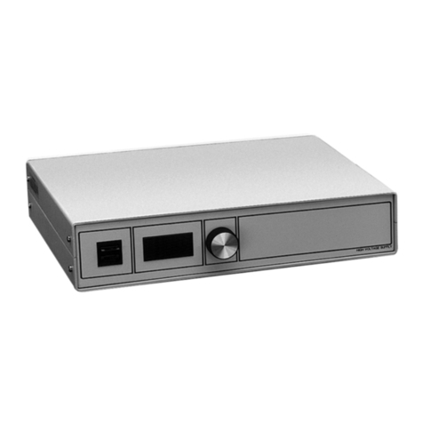
Newport 0901 User manual

USER’S GUIDE
±15 V Current-Limited Power Supply
Model 0901
phone: (877) 835-9620
e-mail: tech@newport.com • www.newport.com

2
EU Declaration of Conformity
We declare that the accompanying product, identified with the CE mark,
complies with requirements of the Electromagnetic Compatibility Directive
2004/108/EC and the Low V oltage Directive 2006/95/EC.
Model Numbers: 0901
Year mark affixed: 2013
Type of Equipment: Electrical equipment for measurement, control and
laboratory use in industrial locations.
Manufacturer: Newport Corporation
1791 Deere A venue
Irvine, CA 92606
Standards Applied:
Compliance was demonstrated to the following standards to the extent
applicable:
BS EN61326-1: 2005/2006 “Electrical equipment for measurement, control and
laboratory use – EMC requirements” for use in a controlled electromagnetic
environment.
This equipment meets the CISPR 11:2011 radiated and conducted emission
limits.
BS EN 61010-1:2011, “Safety requirements for electrical equipment for
measurement, control and laboratory use”.
Mark Carroll
Sr. Director, Instruments Business,
Newport Corporation
Warranty
Newport Corporation guarantees its products to be free of defects for one
year from the date of shipment. This is in lieu of all other guarantees,
expressed or implied, and does not cover incidental or consequential loss.
Information in this document is subject to change without notice. Copyright
2014, 2001-1998, Newport Corporation. All rights reserved. The New Focus
logo and symbol are registered trademarks of Newport Corporation
Document Number 90061076 Rev. A

3
Model 0901 User Guide
Contents
Warranty........................................................................................2
Important User Safety Information ................................4
General Warnings ............................................. 4
Definitions and Symbols .................................. 5
Environmental Specifications ......................... 5
Contact Information ......................................... 6
Introduction.................................................................................7
Getting Started ............................................................ 8
Voltage and Fuse Selection .............................. 8
Operation..................................................................................10
Output Characteristics ................................... 10
Cables .............................................................. 11
Customer Service ...............................................................12
Technical Support ........................................... 12
Service ............................................................. 12

4
IMPORTANT USER SAFETY INFORMATION
–DO NOT DISCARD
General warning in the event of a hazard
• Donotposition this device insuch amanner that
would make it difficult to disconnect the power cord
from the device or the power source.
• Position the equipment so that access tothe mains
disconnect ON/OFF switch on the front panel readily
available.
• Pushthe powerON/OFFswitch inthe frontofthe
device to OFF position to turn OFF the power to
the internal electronics. The OFF position: push the
actuator or switch rocker arm so the “O” depressed.
(To connect power to device, push the actuator or
switch rocker arm so the “1” depressed).
• Fullydisconnect the powercordofthe device from
MAIN power.
Grounding and Powering the device
• Verifythat the line voltage setting onthe rearofthe
Power Supply Model 0901 matches the local Main
Power from the power cord.
• Verifythat properfuses installed foramps andtime
delay.
• Toavoid electronic shock, connect the instrument to
properly earth-ground, 3-prong receptacles by using
the supplied power cord only . Failure to observe this
precaution can reduce equipment performance.
General warning and precaution
• Donotattempttooperatethisequipmentifthereis
evidence of shipping damage or you suspect the unit is
damaged.
• Theusershouldnotattemptanymaintenanceor
service of the device beyond the procedures outlined in
this manual. Any problem that cannot be resolved
should be referred to Newport Technical Support.

5
Model 0901 User Guide
Definitions and Symbols
The following terms and symbols are used in this
documentation and appear on the Model 0901 Power
Supply where safety-related issues occur.
Electronic shock – This symbol indicates a hazard
arising from dangerous voltage. Any mishandling could
result in irreparable damage to the equipment and
personnel injury .
ON Symbol – This symbol represents Power On
OFF Symbol – This symbol represents Power Off
Attention – Refer to the operator instructions of manual
before operating equipment.
O
l
Voltage Requirements 100/120/220/240 ~VAC, 47.5-66Hz
Electrical Ratings 100-120~VAC, 0.5A; and 220-
240~VAC, 0.25A (47.5-660Hz)
Size (H x W x D) [in. (mm)] 3.5 (90.0) x 7.65 (195.0) x 8.0 (200.0)
Mainframe Weight [lb (Kg)] 6.5 (2.8)
Operating Temperature 10ºC to 40ºC (<90% humidity non-
condensing)
Storage T emperature 0ºC to + 50ºC (<90% humidity non-
condensing)
Relative Humidity , Storage <90% humidity non-condensing
Altitude <3000 meters (10000 feet)
Installation Category II
Pollution Degree 2
Use Location Indoor use only
Environment Specification

6
The power entry module requires two 5x20 mm, Slo-Blo fuses. The table
below identifies the correct voltage selector switch setting and fuse rating
for several common AC power .
Input Power Voltage
Switch Setting Fuse Type
100 VAC 100 A
120 VAC 120 A
220 VAC 220 B
240 VAC 240 B
Fuse Type A: Slo-Blo, 250 V , 0.5 A, i 2t ≥ 1.985 A2s, 5 mm x 20 mm
Fuse Type B: Slo-Blo, 250 V , 0.4 A, i 2t ≥ 1.36 A2s, 5 mm x 20 mm
Note: The AC power module requires two fuses. The fuse specifications must match all listed
specification requirements to ensure proper operation.

7
Model 0901 User Guide
Introduction
The Newport Model 0901 Power Supply is a triple output,
low-noise, ±15-V DC power supply. It is intended for use
with all Newport brand products which require ±15-V DC,
and can also serve as a general purpose supply for laboratory
use. It is capable of simultaneously powering three devices,
each requiring ±15 V and up to 300 mA. Two of the outputs
are provided via three-pin M8 style connectors (compatible
with other Newport products), while the third uses banana
jacks. (See Figure 1.)
Figure 1: Model 0901 front panel.

8
Getting Started
Voltage and Fuse Selection
The Model 0901 can operate with an input of 100, 120,
220, or 240 V AC with AC frequencies of 47–63 Hz.
The unit is configured for 120 V AC at the factory; if it will
be used with a different AC voltage, this will need to be
selected on the power module on the back panel. The fuses
may also need to be changed. See below.
To check the voltage setting, look at the voltage indicator
on the AC power module on the back of the power
supply . (See Figure 2.)
Figure 2: Model 0901 rear panel showing AC power module & voltage indicator.
To change the voltage/fuses:
1. Make sure the power supply is turned off.
2. Disconnect the AC power cord.
3. Open the cover of the power module using a small
blade screwdriver or similar tool.

9
Model 0901 User Guide
Figure 3: Power module with the cover open
4. Remove the AC-voltage selection wheel from the unit.
Do not attempt to rotate the wheel while it is still
in the power module; the wheel must be removed,
turned, and then reinserted for proper operation.
(See Figure 3.)
5. Reinsert the wheel in the module so the desired AC
voltage can be viewed in the power-module window.
6. Ensure the proper fuses for the new AC voltage are
installed (see Table 1). Pull out fuse holders to replace
if needed.
7. Close the power-module cover.
8. Verify the proper voltage is showing through the
module window.
9. Reconnect the AC power cord.
Fuse Type A: Slo-Blo, 250 V, 0.5 A, i2t ≥ 1.985 A2s, 5 mm x 20 mm
Fuse Type B: Slo-Blo, 250 V, 0.4 A, i2t ≥ 1.36 A2s, 5 mm x 20 mm
Table 1: The AC power module requires two 5x20-mm, 250-V, Slo-Blo fuses. The current ratings of
the fuses should be as shown.
Input Power Voltage Setting Fuse Type
100 VAC 100 A
120 VAC 120 A
220 VAC 220 B
240 VAC 240 B

10
Operation
Output Characteristics
The outputs (three pairs of ±15 V) of the Model 0901
are all derived from a common linear supply, but each
incorporates independent current-limiting protection as
shown in Figure 4. As a result, the voltage on each
output differs slightly. The impedance of each output is
approximately 2 ohms, so an output will be reduced by
0.6 V when providing the full 300 mA. With no load,
outputs should be ±15 V ±3%.
When a load attempts to draw in excess of 300 – 330 mA
the protection is activated. This is accomplished by
reducing the voltage in order to limit the current to the
maximum rated current.
Figure 4: Block diagram and pin assignments (as seen on front panel) of the Model 0901 power
supply.

11
Model 0901 User Guide
Cables
Newport offers three types of cables for use with the
Model 0901:
Model # Description
0923 cable, M8 connector (male) to M8 connector (male), 1 meter
0923-2 cable, M8 connector (male) to M8 connector (male), 2 meter
0924 cable, 3 banana plugs (male) to M8 connector (male), 1 meter
Models 0923 and 0923-2 are used to connect from the
M8 connectors on the front panel of the Model 0901 to
Newport brand products.
Model 0924 can be used for the following:
- to connect from the banana jacks on the front panel
of the 0901 to Newport brand products
- to connect Newport brand products to a supply
other than an 0901 which has banana jack outputs
- to connect to the M8 connectors on the Model 0901
front panel so as to provide ±15 V on the banana
plugs for general lab use.
When connecting cable Model 0924 to the Model 0901,
note that the colored male-banana plugs on the cable
should follow the color-coding for the Model 0901
banana jacks: red is +15 V , green is ground, and black
is -15 V.

12
Customer Service
Technical Support
Service
Information and advice about the operation of any Newport
product is available from our applications engineers. For quickest
response, ask for “Technical Support” and know the model
number and serial number for your product.
Hours: 8:00–5:00 PST, Monday through Friday (excluding
holidays).
Phone: 1-877-835-9620
Support is also available by email and chat
Chat: Connect with us at www.newport.com
Email: [email protected]
We typically respond to emails within one business day.
In the event that your device malfunctions or becomes damaged,
please contact Newport for a return merchant authorization (RMA)
number and instructions on shipping the unit back for evaluation
and repair.
Table of contents
Other Newport Power Supply manuals
