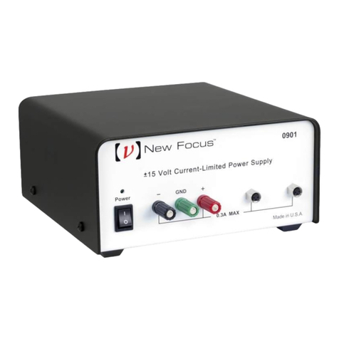
Newport iDRN-PS-1000 User manual

iDRN-PS-1000
UNIVERSAL SWITCHING POWER SUPPLY
Compact DIN-Rail 24 Volt
Ope ato ’s Manual
NEWPORT
Electronics, Inc.
LN
+-

Counte s
F equency
Mete s
PID Cont olle s
Clock/Time s
P inte s
P ocess Mete s
On/Off
Cont olle s
Reco de s
Relative
Humidity
T ansmitte s
The mocouples
The misto s
Wi e
Rate Mete s
Time s
Totalize s
St ain Gauge
Mete s
Voltmete s
Multimete s
Solde ing I on
Teste s
pH pens
pH Cont olle s
pH Elect odes
RTDs
The mowells
Flow Senso s
Fo Immediate Assistance
In the U.S.A. and Canada: 1-800-NEWPORT
®
In Mexico: (95) 800-NEWPORT
SM
O call you local NEWPORT Office.
It is the policy of NEWPORT to comply with all wo ldwide safety and EMC/EMI egulations
that apply. NEWPORT is constantly pu suing ce tification of its p oducts to the Eu opean
New App oach Di ectives. NEWPORT will add the CE ma k to eve y app op iate device
upon ce tification.
The info mation contained in this document is believed to be co ect but NEWPORT
Elect onics, Inc. accepts no liability fo any e o s it contains, and ese ves the ight to
alte specifications without notice.
WARNING: These p oducts a e not designed fo use in, and should not be used fo ,
patient connected applications.
Internet e-mail
info@newpo tUS.com
Additional p oducts f om
NEWPORTnetSM On-Line Service
http://www.newpo tUS.com
NEWPORT
Electronics, Inc.
This device is ma ked with the inte national caution symbol. It is impo tant to ead the Setup Guide befo e
installing o commissioning this device as it contains impo tant info mation elating to safety and EMC.

1. Gene al Info mation and Featu es 2
2. Safety Conside ations 3
3. Installation and Removal 4
3.1 Installation Clea ance 5
3.2 Mounting on DIN Rail 6
3.3 Removal of Unit 7
4. Input and Output Connections 8
4.1 Block Diag am 8
4.2 Wi ing fo 115 Vac - Single Phase 9
4.3 Wi ing fo 230 Vac - Two Phase 10
5. Specifications 11
Input Powe 11
Output Powe 11
Gene al 12
Wi e Connections 12
6. Dimensions 13
7. Tempe atu e De ating G aph 14
CONTENTS
1

The compact iDRN powe supplies a e designed to
supply well- egulated 24 volt DC powe to senso s,
signal conditione s, data acquisition systems and
high level logic equipment.
Significant iDRN featu es include:
• Tested isolation, p ima y to output
• Recessed live pa ts and connecto sc ews
• 35mm DIN ail mounting
• Wide input voltage tole ances
• P otective va isto input shunt
• Input AC spike ejection with LC filte s
• LED powe -on lamp
• Ove -tempe atu e p otection
• Sho t ci cuit p otection
• Low- ipple, well- egulated design
Features
GENERAL INFORMATION AND FEATURES
1
2

SAFETY CONSIDERATIONS
2
3
This device is ma ked with the inte national Caution symbol. It is
impo tant to ead this manual befo e installing o commissioning this
device as it contains impo tant info mation elating to Safety and EMC
(Elect omagnetic Compatibility).
npacking & Inspection
Unpack the inst ument and inspect fo obvious shipping damage. Do not attempt to
ope ate the unit if damage is found.
This inst ument is a DIN ail mount device. Installation of this inst ument should be done
by Qualified pe sonnel. In o de to ensu e safe ope ation, the following inst uctions
should be followed.
This inst ument has no powe -on switch. An exte nal switch o ci cuit-b eake shall be included in the
building installation as a disconnecting device. It shall be ma ked to indicate this function, and it shall
be in close p oximity to the equipment within easy each of the ope ato . The switch o ci cuit-b eake
shall not inte upt the P otective Conducto (Ea th wi e), and it shall meet the elevant equi ements
of IEC 947–1 and IEC 947-3 (Inte national Elect otechnical Commission). The switch shall not be
inco po ated in the mains supply co d.
Fu the mo e, to p ovide p otection against excessive ene gy being d awn f om the mains supply in
case of a fault in the equipment, an ove cu ent p otection device shall be installed.
• The Protective Conductor must be connected fo safety easons. Check that the
powe cable has the p ope Ea th wi e, and it is p ope ly connected. It is not safe to
ope ate this unit without the P otective Conducto Te minal connected.
• Do not exceed voltage ating on the label located on the top of the inst ument
housing.
• Always disconnect powe befo e changing signal and powe connections.
• Do not use this inst ument on a wo k bench without its case fo safety easons.
• Do not ope ate this inst ument in flammable o explosive atmosphe es.
• Do not expose this inst ument to ain o moistu e.
• Unit mounting should allow fo adequate ventilation to ensu e inst ument does not
exceed ope ating tempe atu e ating.
• Use elect ical wi es with adequate size to handle mechanical st ain and powe
equi ements. Install without exposing ba e wi e outside the connecto to minimize
elect ical shock haza ds.
EMC Considerations
• Wheneve EMC is an issue, always use shielded cables.
• Neve un signal and powe wi es in the same conduit.
• Use signal wi e connections with twisted-pai cables.
• Install Fe ite Bead(s) on signal wi es close to the inst ument if EMC p oblems
pe sist.

If a ail assembly is to be t anspo ted, then
disconnection, dismounting and sepa ate
packing of the powe supply is
ecommended.
Fo units that must be shipped installed on
the ail, additional b acing to esist
t anspo tation shocks is ecommended.
Do not attempt to install o connect to the
powe supply when the mains a e
ene gized.
Warning!
INSTALLATION AND REMOVAL
3
4

3.1 Installation Clearance
Ensu e that the e is enough oom fo mounting the powe
supply unit. The e should be a minimum of 1" [25mm] spacing
to allow sufficient ai ci culation fo p ope cooling.
Figure 3.1 — Mounting
INSTALLATION AND REMOVAL
3
5
DC POWER OUT
AC POWER IN
DC POWER IN
SIGNAL INPUT
DC POWER IN
SIGNAL INPUT
DC POWER IN
SIGNAL INPUT
DIN RAIL
SIGNAL
CONDITIONER
MODULES
24V-BUS
POWER SUPPLY
1" [25mm] 1" [25mm]

3.2 Mounting on DIN Rail
To install unit onto DIN Rail
1. Tilt unit, position mounting slot onto DIN Rail, as shown.
2. Push unit towa ds DIN Rail and it will snap into place.
Figure 3.2
—
Mounting on 35mm DIN Rail
INSTALLATION AND REMOVAL
3
6

3
7
3.3 Removal of nit
1. Inse t flat sc ew-d ive into tab and push downwa ds.
2. Unit will detach f om DIN Rail.
Figure 3.3 — Removal of nit
INSTALLATION AND REMOVAL

4
8
4.1 Block Diagram of Power Supply
Figure 4.1 — Block Diagram
4.2 Wiring
Warning: Do not tu n on the ac powe to the powe supply
unit until you have completed all output connections. Failu e
to do so may esult in inju y!
This device must only be installed elect ically by a specially
t ained elect ician with co esponding qualifications.
Warning: To avoid potential elect ic shock use National
Elect ical Code (NEC) safety p actices when wi ing and
connecting this unit to a powe sou ce.
INPUT AND OUTPUT CONNECTIONS

4
9
INPUT AND OUTPUT CONNECTIONS
4.2 Wiring (Continued)
115Vac - Single phase powe wi ing
Figure 4.2— Wiring for 115Vac - Single Phase
LN
+-
Output Voltage
(for shiel e wire
connections, if necessary)
Earth
FUSE 1
LINE
Switch
NEUTRAL
Earth
Switch
*
*
USE A SWITCH TO APPLY
+24V POWER TO THE LOAD,
IF THE CAPACITANCE OF
THE LOAD WILL DRAW MORE
THAN 7 AMPS AT TURN ON.
Earth
Return
+24 V
To Signal
Con itioner
Mo ules
Input Power
USE AWG 12-26 WIRE

4.3 Wiring (Continued)
230Vac - Two phase powe wi ing
Figure 4.3— Wiring for 230Vac - Two Phase
INPUT AND OUTPUT CONNECTIONS
4
10
LN
+-
Output Voltage
(for shiel e wire
connections, if necessary)
Earth
FUSE 1
L1
Switch
L2
Earth
FUSE 2
Switch
*
*
USE A SWITCH TO APPLY
+24V POWER TO THE LOAD,
IF THE CAPACITANCE OF
THE LOAD WILL DRAW MORE
THAN 7 AMPS AT TURN ON.
Earth
Return
+24 V
To Signal
Con itioner
Mo ules
Input Power
USE AWG 12-26 WIRE

SPECIFICATIONS
5
11
INP T POWER
Input Voltage: 115 - 240Vac ±10%
F equency: 50/60 Hz
Cu ent: 0.400A @ 103Vac
0.190A @ 265Vac
Ove voltage P otection: 275 Volt Va isto
Ove cu ent P otection: Fuse TR-5 800mA Time-lag / IEC 127-3
Input Wattage: 26 Watts
O TP T POWER
Output Voltage: 24Vdc ±2% @ 850mA (Resistive Load)
Output Wattage: 20 Watts*
* Fo highe output wattage g eate than 20 watts follow the cha t on
section 7, Figu e 6.2.
Ripple: less than 100 mV ms
Ope ating Indicato : F ont Panel LED
Sho t-Ci cuit/
Ove load P otection: Cu ent limiting with automatic sho t-
ci cuit p otection and tempe atu e
shutdown accomplished by the switche .
Maximum numbe of
Signal Conditione Depends on module used and
modules powe ed: configu ation (6-10 modules)

SPECIFICATIONS
5
12
GENERAL
Ope ating Tempe atu e: 23° to 122°F(-5° to 50°C)
Sto age Tempe atu e: -40° to 176°F(-40° to 80°C)
Mounting: 35mm DIN Rail
Size: Height: 3.55" (90mm)
Width: 0.99" (25mm)
Depth: 4.38" (111mm)
Weight: 0.3 lbs. (0.14 kg)
Equipment Type: CLASS I
Ove voltage: CAT II
Pollution Deg ee: 2
Insulation input to ouput: Dielect ic st ength to 2500V t ansient
based on EN61010 fo 265V ms
wo king voltage
WIRE CONNECTIONS
Sc ew down wi e clamps, AWG 12 to 26 (fe ules ecommended
fo st anded wi e).

DIMENSIONS
6
13

INPUT AC VOLTAGE / POWER OUTPUT
7
14
Example: If ambient is 50ºC, maximum wattage is 21W max. fo
120-265Vac. If unit is ope ated at 21W at an input voltage of 100V,
the maximum ambient tempe atu e allowed is 40ºC.
Figure 6.2 — Temperature Derating Graph
MAXIMUM POWER OUTPUT
INPUT AC
VOLTAGE
AMBIENT TEMPERATURE ºC
120V 265V
115V
110V
105V
100V
25ºC
-5ºC 30ºC 35ºC 40ºC 45ºC 50ºC
20W
24W 23W 22W 21W
AC INP T C RRENT @ 100VAC INP T
O TP T POWER AC C RRENT
20W 338mA
21W 355mA
22W 373mA
23W 392mA
24W 412mA

NOTES
15

NOTES
16

Warranty/Disclaimer
NEWPORT ELECTRONICS, INC. wa ants this unit to be f ee of defects in mate ials and
wo kmanship fo a pe iod of one (1) yea f om date of pu chase. In addition to NEWPORT’s standa d
wa anty pe iod, NEWPORT ELECTRONICS will extend the wa anty pe iod fo one (1) additional yea
if the wa anty ca d enclosed with each inst ument is etu ned to NEWPORT.
If the unit should malfunction, it must be etu ned to the facto y fo evaluation. NEWPORT’s Custome
Se vice Depa tment will issue an Autho ized Retu n (AR) numbe immediately upon phone o w itten
equest. Upon examination by NEWPORT, if the unit is found to be defective it will be epai ed o
eplaced at no cha ge. NEWPORT’s WARRANTY does not apply to defects esulting f om any action
of the pu chase , including but not limited to mishandling, imp ope inte facing, ope ation outside of
design limits, imp ope epai , o unautho ized modification. This WARRANTY is VOID if the unit
shows evidence of having been tampe ed with o shows evidence of being damaged as a esult of
excessive co osion; o cu ent, heat, moistu e o vib ation; imp ope specification; misapplication;
misuse o othe ope ating conditions outside of NEWPORT’s cont ol. Components which wea a e not
wa anted, including but not limited to contact points, fuses, and t iacs.
NEWPORT is pleased to offer suggestions on the use of its various products.
However, NEWPORT neither assumes responsibility for any omissions or errors nor
assumes liability for any damages that result from the use of its products in
accordance with information provided by NEWPORT, either verbal or written.
NEWPORT warrants only that the parts manufactured by it will be as specified and
free of defects. NEWPORT MAKES NO OTHER WARRANTIES OR
REPRESENTATIONS OF ANY KIND WHATSOEVER, EXPRESSED OR IMPLIED,
EXCEPT THAT OF TITLE, AND ALL IMPLIED WARRANTIES INCL DING ANY
WARRANTY OF MERCHANTABILITY AND FITNESS FOR A PARTIC LAR P RPOSE
ARE HEREBY DISCLAIMED. LIMITATION OF LIABILITY: The remedies of purchaser
set forth herein are exclusive and the total liability of NEWPORT with respect to
this order, whether based on contract, warranty, negligence, indemnification,
strict liability or otherwise, shall not exceed the purchase price of the component
upon which liability is based. In no event shall NEWPORT be liable for
consequential, incidental or special damages.
CONDITIONS: Equipment sold by NEWPORT is not intended to be used, no shall it be used: (1) as a
“Basic Component” unde 10 CFR 21 (NRC), used in o with any nuclea installation o activity; o (2)
in medical applications o used on humans. Should any P oduct(s) be used in o with any nuclea
installation o activity, medical application, used on humans, o misused in any way, NEWPORT
assumes no esponsibility as set fo th in ou basic WARRANTY/DISCLAIMER language, and
additionally, pu chase will indemnify NEWPORT and hold NEWPORT ha mless f om any liability o
damage whatsoeve a ising out of the use of the P oduct(s) in such a manne .
Di ect all wa anty and epai equests/inqui ies to the NEWPORT Custome Se vice Depa tment.
BEFORE RETURNING ANY PRODUCT(S) TO NEWPORT, PURCHASER MUST OBTAIN AN
AUTHORIZED RETURN (AR) NUMBER FROM NEWPORT’S CUSTOMER SERVICE DEPARTMENT
(IN ORDER TO AVOID PROCESSING DELAYS). The assigned AR numbe should then be ma ked
on the outside of the etu n package and on any co espondence.
The pu chase is esponsible fo shipping cha ges, f eight, insu ance and p ope packaging to
p event b eakage in t ansit.
FOR WARRANTY RETURNS, please have
the following info mation available BEFORE
contacting NEWPORT:
1. P.O. numbe unde which the p oduct was
PURCHASED,
2. Model and se ial numbe of the p oduct unde
wa anty, and
3. Repai inst uctions and/o specific p oblems
elative to the p oduct.
FOR NON-WARRANTY REPAIRS, consult
NEWPORT fo cu ent epai cha ges. Have the
following info mation available BEFORE
contacting NEWPORT:
1. P.O. numbe to cove the COST
of the epai ,
2. Model and se ial numbe of
p oduct, and
3. Repai inst uctions and/o specific
p oblems elative to the p oduct.
NEWPORT’s policy is to make unning changes, not model changes, wheneve an imp ovement is possible.
This affo ds ou custome s the latest in technology and enginee ing.
NEWPORT is a egiste ed t adema k of NEWPORT ELECTRONICS, INC.
© Copy ight 2002 NEWPORT ELECTRONICS, INC. All ights ese ved. This document may not be
copied, photocopied, ep oduced, t anslated, o educed to any elect onic medium o machine- eadable
fo m, in whole o in pa t, without p io w itten consent of NEWPORT ELECTRONICS, INC.
Return Requests/Inquiries
PATENT NOTICE: This p oduct is cove ed by one o mo e of the following patents: U.S. Pat. No. Des. 336,895;
5,274,577 / Canada 2052599; 2052600 / Italy 1249456; 1250938 / F ance B evet No. 91 12756 / Spain
2039150; 2048066 / UK Patent No. GB2 249 837; GB2 248 954 / Ge many DE 41 34398 C2
Othe Inte national Patents Pending.

M2540/N/0202
Fo immediate technical o application assistance please call:
Newpo t Elect onics, Inc.
2229 South Yale St eet • Santa Ana, CA • 92704 • U.S.A.
TEL: (714) 540-4914 • FAX: (714) 546-3022
Toll F ee: 1-800-639-7678 • http://www.newpo tUS.com • e-mail:info@newpo tUS.com
ISO 9001 Ce tified
Newpo t Technologies, Inc.
976 Be ga • Laval (Quebec) • H7L 5A1 • Canada
TEL: (514) 335-3183 • FAX: (514) 856-6886
Toll F ee: 1-800-639-7678 • http://www.newpo t.ca • e-mail:sales@newpo t.ca
Newpo t Elect onics, Ltd.
One Omega D ive • Rive Bend Technology Cent e
No thbank, I lam • Mancheste M44 5BD • United Kingdom
Tel: +44 161 777 6611 • FAX: +44 161 777 6622
Toll F ee: 0800 488 488 • http://www.newpo tuk.co.uk • e-mail:sales@newpo tuk.co.uk
Newpo t Elect onics B.V.
Postbus 8034 • 1180 LA Amstelveen • The Nethe lands
TEL: +31 20 3472121 • FAX: +31 20 6434643
Toll F ee: 0800 0993344 • http://www.newpo t.nl • e-mail: sales@newpo t.nl
Newpo t Elect onics spol s. .o.
Rudé a mády 1868, 733 01 Ka viná 8 • Czech Republic
TEL: +420 69 6311899 • FAX: +420 69 6311114
Toll F ee: 0800-1-66342 • http://www.newpo t.cz • e-mail: sales@newpo t.cz
Newpo t Elect onics GmbH
Daimle st asse 26 • D-75392 Deckenpf onn • Ge many
TEL: 49 7056 9398-0 • FAX: 49 7056 9398-29
Toll F ee: 0800 / 6397678 • http://www.newpo t.de • e-mail: sales@newpo t.de
Newpo t Elect onique S.A.R.L.
9, ue Denis Papin • 78190 T appes • F ance
TEL: +33 130 621 400 • FAX: +33 130 699 120
Toll F ee: 0800-4-06342 • http://www.newpo t.f • e-mail: sales@newpo t.f
Mexico and Latin Ame ica
TEL: 001-800-826-6342 • FAX: 001 (203) 359-7807
En Español: 001 (203) 359-7803
®
Table of contents
Other Newport Power Supply manuals
Popular Power Supply manuals by other brands

Videx
Videx 520MR Installation instruction

Poppstar
Poppstar 1008821 Instructions for use

TDK-Lambda
TDK-Lambda LZS-A1000-3 Installation, operation and maintenance manual

TDK-Lambda
TDK-Lambda 500A instruction manual

Calira
Calira EVS 17/07-DS/IU operating instructions

Monacor
Monacor PS-12CCD instruction manual


