Sony HBD-E570 User manual

SERVICE MANUAL
Sony Corporation
Audio&Video Business Group
Published by Sony Techno Create Corporation
HBD-E370/E470/
E570/E870/T57
SPECIFICATIONS
BLU-RAY DISC/DVD RECEIVER
9-889-770-01
2010B05-1
© 2010.02
US Model
HBD-E370/E570/T57
Canadian Model
HBD-E370/E470/E870
AEP Model
UK Model
HBD-E370/E870
Ver. 1.0 2010.02
• HBD-E370 is the amplifier, video, BD/DVD/Super Audio CD/CD
system, USB, LAN and tuner section in BDV-E370.
• HBD-E470 is the amplifier, video, BD/DVD/Super Audio CD/CD
system, USB, LAN and tuner section in BDV-E470.
• HBD-E570 is the amplifier, video, BD/DVD/Super Audio CD/CD
system, USB, LAN and tuner section in BDV-E570.
• HBD-E870 is the amplifier, video, BD/DVD/Super Audio CD/CD
system, USB, LAN and tuner section in BDV-E870.
• HBD-T57 is the amplifier, video, BD/DVD/Super Audio CD/CD
system, USB, LAN and tuner section in BDV-T57.
Model Name Using Similar Mechanism BDP-S370
Mechanism Type BPX-5
Optical Pick-up Block Name KEM-460AAA
Photo: HBD-E370
Amplifier Section
U.S. models:
POWER OUTPUT AND TOTAL HARMONIC
DISTORTION:
(FTC)
Front L + Front R: With 3 ohms loads, both
channels driven, from 180
- 20,000 Hz; rated 60 watts
per channel minimum
RMS power, with no more
than 1% total harmonic
distortion from 250 milli
watts to rated output.
Other models:
POWER OUTPUT (rated)
Front L/Front R: 108 W + 108 W (at 3 ohms,
1 kHz, 1% THD)
HBD-E370:
POWER OUTPUT (reference)
Front L/Front R/Center/Surround L/Surround R:
142 W (per channel at 3
ohms, 1 kHz)
Subwoofer: 140 W (at 3 ohms, 80 Hz)
HBD-E870/HBD-E570/HBD-E470/HBD-T57:
POWER OUTPUT (reference)
Front L/Front R/Center/Surround L/Surround R:
167 W (per channel at 3
ohms, 1 kHz)
Subwoofer: 165 W (at 3 ohms, 80 Hz)
Inputs (Analog)
AUDIO (AUDIO IN) Sensitivity: 450/250 mV
Inputs (Digital)
SAT/CABLE (COAXIAL), TV (OPTICAL)
Supported formats: LPCM
2CH (up to 48 kHz), Dolby
Digital, DTS
Video Section
Outputs VIDEO: 1 Vp-p 75 ohms
COMPONENT:
Y: 1 Vp-p 75 ohms
PB/CB, PR/CR: 0.7 Vp-p
75 ohms
HDMI OUT: Type A (19
pin)
BD/DVD/Super Audio CD/CD System
Signal format system NTSC (US and
USB Section
(USB) port: Type A (For connecting
USB memory, memory
card reader, digital still
camera, and digital video
camera)
Maximum current: 500 mA
LAN Section
LAN (100) terminal 100BASE-TX Terminal
Tuner Section
System PLL quartz-locked digital
synthesizer
FM tuner section
Tuning range
North American models: 87.5 MHz - 108.0 MHz
(100 kHz step)
Other models: 87.5 MHz - 108.0 MHz
(50 kHz step)
Antenna (aerial) FM wire antenna (aerial)
Antenna (aerial) terminals 75 ohms, unbalanced
Intermediate frequency 10.7 MHz
General
Power requirements
North American model: 120 V AC, 60 Hz
Other models:
50/60 Hz
Power consumption On: 170 W
Standby: 0.3 W (at the
Power Saving mode)
Dimensions (approx.) 430 mm × 85 mm × 335
mm (17 in × 3 3/8in ×
13 1/4in) (w/h/d) incl.
projecting parts
Mass (approx.) 4.8 kg (10 lb 10 oz)
Design and specifications are subject to change
without notice.
Canadian models)
PAL/NTSC (AEP and
UK models)
220 - 240 V AC,
w
w
w
.
x
i
a
o
y
u
1
6
3
.
c
o
m
Q
Q
3
7
6
3
1
5
1
5
0
9
9
2
8
9
4
2
9
8
T
E
L
1
3
9
4
2
2
9
6
5
1
3
9
9
2
8
9
4
2
9
8
0
5
1
5
1
3
6
7
3
Q
Q
TEL 13942296513 QQ 376315150 892498299
http://www.xiaoyu163.com

HBD-E370/E470/E570/E870/T57
2
NOTES ON CHIP COMPONENT REPLACEMENT
• Never reuse a disconnected chip component.
• Notice that the minus side of a tantalum capacitor may be dam-
aged by heat.
FLEXIBLE CIRCUIT BOARD REPAIRING
• Keep the temperature of soldering iron around 270 °C during
repairing.
• Do not touch the soldering iron on the same conductor of the
circuit board (within 3 times).
• Be careful not to apply force on the conductor when soldering
or unsoldering.
SAFETY CHECK-OUT
After correcting the original service problem, perform the follow-
ing safety check before releasing the set to the customer:
Check the antenna terminals, metal trim, “metallized” knobs,
screws, and all other exposed metal parts for AC leakage.
Check leakage as described below.
LEAKAGE TEST
The AC leakage from any exposed metal part to earth ground and
from all exposed metal parts to any exposed metal part having a
return to chassis, must not exceed 0.5 mA (500 microamperes.).
Leakage current can be measured by any one of three methods.
1. A commercial leakage tester, such as the Simpson 229 or RCA
WT-540A. Follow the manufacturers’ instructions to use these
instruments.
2. A battery-operated AC milliammeter. The Data Precision 245
digital multimeter is suitable for this job.
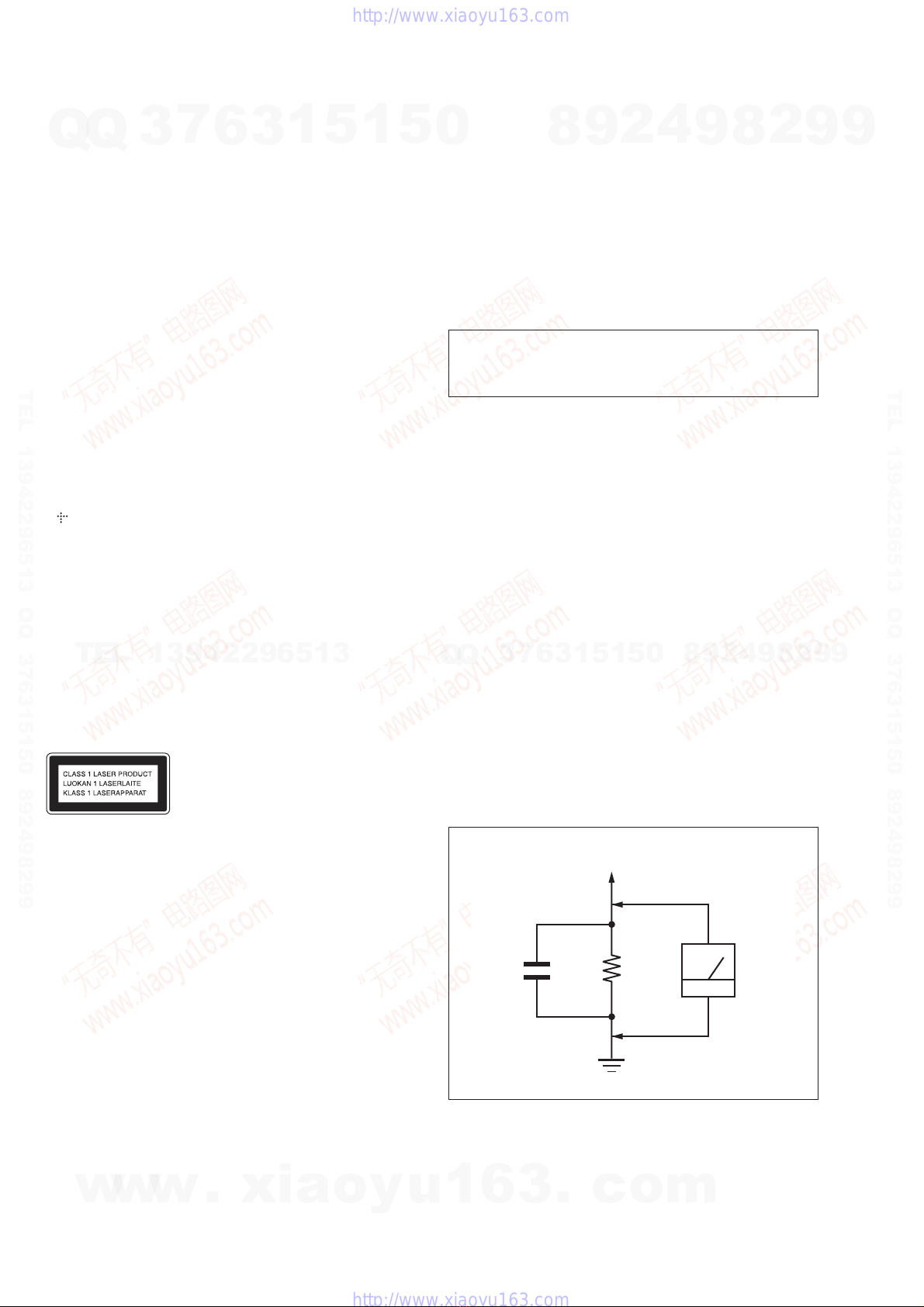
3. Measuring the voltage drop across a resistor by means of a
VOM or battery-operated AC voltmeter. The “limit” indication
is 0.75 V, so analog meters must have an accurate low-voltage
scale. The Simpson 250 and Sanwa SH-63Trd are examples
of a passive VOM that is suitable. Nearly all battery operated
digital multimeters that have a 2 V AC range are suitable. (See
Fig. A)
1.5 kΩ0.15 μF
AC
voltmeter
(0.75 V)
To Exposed Metal
Parts on Set
Earth Ground
Fig. A. Using an AC voltmeter to check AC leakage.
SAFETY-RELATED COMPONENT WARNING!
COMPONENTS IDENTIFIED BY MARK 0OR DOTTED LINE
WITH MARK 0ON THE SCHEMATIC DIAGRAMS AND IN
THE PARTS LIST ARE CRITICAL TO SAFE OPERATION.
REPLACE THESE COMPONENTS WITH SONY PARTS
WHOSE PART NUMBERS APPEAR AS SHOWN IN THIS
MANUAL OR IN SUPPLEMENTS PUBLISHED BY SONY.
ATTENTION AU COMPOSANT AYANT RAPPORT
À LA SÉCURITÉ!
LES COMPOSANTS IDENTIFIÉS PAR UNE MARQUE 0SUR
LES DIAGRAMMES SCHÉMATIQUES ET LA LISTE DES
PIÈCES SONT CRITIQUES POUR LA SÉCURITÉ DE FONC-
TIONNEMENT. NE REMPLACER CES COMPOSANTS QUE
PAR DES PIÈCES SONY DONT LES NUMÉROS SONT DON-
NÉS DANS CE MANUEL OU DANS LES SUPPLÉMENTS
PUBLIÉS PAR SONY.
• This product incorporates copyright protection technology that is protected by
U.S. patents and other intellectual property rights.
Use of this copyright protection technology must be authorized by Macrovision,
and is intended for home and other limited viewing uses only unless otherwise
authorized by Macrovision.
Reverse engineering or disassembly is prohibited.
• This system incorporates with Dolby* Digital and Dolby Pro Logic (II) adaptive
matrix surround decoder and the DTS** Digital Surround System.
* Manufactured under license from Dolby Laboratories.
Dolby, Pro Logic, and the double-D symbol are trademarks of Dolby Labora-
tories.
**Manufactured under license under U.S. Patent #’s:
5,451,942; 5,956,674; 5,974,380; 5,978,762; 6,226,616; 6,487,535;
7,212,872; 7,333,929; 7,392,195; 7,272,567 & other U.S. and worldwide
patents issued & pending. DTS is a registered trademark and the DTS logos,
Symbol, DTS-HD and DTS-HD Master Audio are trademarks of DTS, Inc.
© 1996-2008 DTS, Inc. All Rights Reserved.
• This system incorporates High-Definition Multimedia Interface (HDMI™) tech-
nology.
HDMI, the HDMI logo and High-Definition Multimedia Interface are trademarks
or registered trademarks of HDMI Licensing LLC.
• Java and all Java-based trademarks and logos are trademarks or registered trade-
marks of Sun Microsystems, Inc.
• “BD-LIVE” and “BONUSVIEW” are trademarks of Blu-ray Disc Association.
• “Blu-ray Disc” is a trademark.
• “Blu-ray Disc,” “DVD+RW,” “DVD-RW,” “DVD+R,” “DVD-R,” “DVD
VIDEO,” and “CD” logos are trademarks.
• “BRAVIA” is a trademark of Sony Corporation.
• “AVCHD” and the “AVCHD” logo are trademarks of Matsushita Electric Indus-
trial Co., Ltd. and Sony Corporation.
• “S-AIR” and its logo are trademarks of Sony Corporation.
• , “XMB,” and “xross media bar” are trademarks of Sony Corporation and Sony
Computer Entertainment Inc.
• “PLAYSTATION” is a trademark of Sony Computer Entertainment Inc.
• DivX®, DivX Certified®and associated logos are registered trademarks of DivX,
Inc. and are used under license. (Except for U.S. models.)
• Music and video recognition technology and related data are provided by Grace-
note®.
Gracenote is the industry standard in music recognition technology and related
content delivery. For more information, please visit www.gracenote.com.
CD, DVD, Blu-ray Disc, and music and video-related data from Gracenote, Inc.,
copyright © 2000-present Gracenote.
Gracenote Software, copyright © 2000-present Gracenote. One or more patents
owned by Gracenote apply to this product and service. See the Gracenote website
for a nonexhaustive list of applicable Gracenote patents. Gracenote, CDDB,
MusicID, MediaVOCS, the Gracenote logo and logotype, and the “Powered by
Gracenote” logo are either registered trademarks or trademarks of Gracenote in
the United States and/or other countries.
This appliance is classified as a
CLASS 1 LASER product. This
marking is located on the rear
exterior.
CAUTION
Use of controls or adjustments or performance of procedures
other than those specified herein may result in hazardous radia-
tion exposure.
w
w
w
.
x
i
a
o
y
u
1
6
3
.
c
o
m
Q
Q
3
7
6
3
1
5
1
5
0
9
9
2
8
9
4
2
9
8
T
E
L
1
3
9
4
2
2
9
6
5
1
3
9
9
2
8
9
4
2
9
8
0
5
1
5
1
3
6
7
3
Q
Q
TEL 13942296513 QQ 376315150 892498299
http://www.xiaoyu163.com

HBD-E370/E470/E570/E870/T57
3
1. SERVICING NOTES ............................................. 4
2. DISASSEMBLY
2-1. Disassembly Flow........................................................... 11
2-2. Case (EZ) ........................................................................ 11
2-3. MB-134 Board ................................................................ 12
2-4. Bracket (MB) Block........................................................ 13
2-5. Fuse (F901), POWER Board .......................................... 13
2-6. Front Panel Block ........................................................... 14
2-7. CONNECT Board........................................................... 14
2-8. BD Drive (BPX-5).......................................................... 15
2-9. Back Panel Block............................................................ 15
2-10. MAIN Board ................................................................... 16
2-11. AUDIO Board................................................................. 16
2-12. Optical Device (KEM-460AAA), Wire (Flat Type) ....... 17
3. TEST MODE ............................................................ 18
4. ELECTRICAL CHECK ......................................... 27
5. DIAGRAMS
5-1. Block Diagram - SERVO Section - ................................ 28
5-2. Block Diagram - MEMORY Section -............................ 29
5-3. Block Diagram - TUNER, S-AIR Section -.................... 30
5-4. Block Diagram - AUDIO Section -................................. 31
5-5. Block Diagram - REGULATOR Section -...................... 32
5-6. Block Diagram
- PANEL, POWER SUPPLY Section -........................... 33
5-7. Schematic Diagram - MB-134 Board (1/13) -................ 35
5-8. Schematic Diagram - MB-134 Board (2/13) -................ 36
5-9. Schematic Diagram - MB-134 Board (3/13) -................ 37
5-10. Schematic Diagram - MB-134 Board (4/13) -................ 38
5-11. Schematic Diagram - MB-134 Board (5/13) - ................ 39
5-12. Schematic Diagram - MB-134 Board (6/13) -................ 40
5-13. Schematic Diagram - MB-134 Board (7/13) -................ 41
5-14. Schematic Diagram - MB-134 Board (8/13) -................ 42
5-15. Schematic Diagram - MB-134 Board (9/13) -................ 43
5-16. Schematic Diagram - MB-134 Board (10/13) -.............. 44
TABLE OF CONTENTS
5-17. Schematic Diagram - MB-134 Board (11/13) - .............. 45
5-18. Schematic Diagram - MB-134 Board (12/13) -.............. 46
5-19. Schematic Diagram - MB-134 Board (13/13) -.............. 47
5-20. Printed Wiring Board
- MB-134 Board (Component Side) - ............................. 48
5-21. Printed Wiring Board
- MB-134 Board (Conductor Side) -............................... 49
5-22. Printed Wiring Board - AUDIO Board -......................... 50
5-23. Schematic Diagram - AUDIO Board -............................ 51
5-24. Printed Wiring Board
- MAIN Board (Component Side) -................................ 52
5-25. Printed Wiring Board
- MAIN Board (Conductor Side) -.................................. 53
5-26. Schematic Diagram - MAIN Board (1/5) -..................... 54
5-27. Schematic Diagram - MAIN Board (2/5) -..................... 55
5-28. Schematic Diagram - MAIN Board (3/5) -..................... 56
5-29. Schematic Diagram - MAIN Board (4/5) -..................... 57
5-30. Schematic Diagram - MAIN Board (5/5) -..................... 58
5-31. Printed Wiring Board - CONNECT Board -................... 59
5-32. Schematic Diagram - CONNECT Board -...................... 59
5-33. Printed Wiring Board - REG Board -.............................. 60
5-34. Schematic Diagram - REG Board - ................................ 61
5-35. Printed Wiring Board - FL Board - ................................. 62
5-36. Schematic Diagram - FL Board -.................................... 63
5-37. Printed Wiring Board - POWER Board -........................ 64
5-38. Schematic Diagram - POWER Board - .......................... 65
5-39. Printed Wiring Boards - KEY Section -.......................... 66
5-40. Schematic Diagram - KEY Section - .............................. 66
6. EXPLODED VIEWS
6-1. Case, Front Panel Section ............................................... 91
6-2. MB-134 Board Section ................................................... 92
6-3. Back Panel Section ......................................................... 93
6-4. MAIN Board Section...................................................... 94
6-5. BD Drive Section (BPX-5)............................................. 95
7. ELECTRICAL PARTS LIST .............................. 96
w
w
w
.
x
i
a
o
y
u
1
6
3
.
c
o
m
Q
Q
3
7
6
3
1
5
1
5
0
9
9
2
8
9
4
2
9
8
T
E
L
1
3
9
4
2
2
9
6
5
1
3
9
9
2
8
9
4
2
9
8
0
5
1
5
1
3
6
7
3
Q
Q
TEL 13942296513 QQ 376315150 892498299
http://www.xiaoyu163.com

HBD-E370/E470/E570/E870/T57
4
SECTION 1
SERVICING NOTES
NOTES ON HANDLING THE OPTICAL PICK-UP
BLOCK OR BASE UNIT
The laser diode in the optical pick-up block may suffer electro-
static break-down because of the potential difference generated by
the charged electrostatic load, etc. on clothing and the human body.
During repair, pay attention to electrostatic break-down and also
use the procedure in the printed matter which is included in the
repair parts.
The flexible board is easily damaged and should be handled with
care.
NOTES ON LASER DIODE EMISSION CHECK
The laser beam on this model is concentrated so as to be focused
on the disc reflective surface by the objective lens in the optical
pickup block. Therefore, when checking the laser diode emission,
observe from more than 30 cm away from the objective lens.
UNLEADED SOLDER
Boards requiring use of unleaded solder are printed with the lead-
free mark (LF) indicating the solder contains no lead.
(Caution: Some printed circuit boards may not come printed with
the lead free mark due to their particular size)
: LEAD FREE MARK
Unleaded solder has the following characteristics.
• Unleaded solder melts at a temperature about 40 °C higher
than ordinary solder.
Ordinary soldering irons can be used but the iron tip has to be
applied to the solder joint for a slightly longer time.
Soldering irons using a temperature regulator should be set to
about 350 °C.
Caution: The printed pattern (copper foil) may peel away if
the heated tip is applied for too long, so be careful!
• Strong viscosity
Unleaded solder is more viscous (sticky, less prone to flow)
than ordinary solder so use caution not to let solder bridges
occur such as on IC pins, etc.
• Usable with ordinary solder
It is best to use only unleaded solder but unleaded solder may
also be added to ordinary solder.
Part No. Description Layer
J-6090-199-A BLX-104 Single Layer
J-6090-200-A BLX-204 Dual Layer
J-2501-307-A CD (HLX-A1)
J-2501-305-A HLX-513 Single Layer (NTSC)
J-2501-306-A HLX-514 Dual Layer (NTSC)
J-6090-077-A HLX-506 Single Layer (PAL)
J-6090-078-A HLX-507 Dual Layer (PAL)
TEST DISC
Note: Refer to the service manual of BDP-BX1/S350 (Part No. 9-883-
989-1[]) (page 1-3 to 1-14E) for the use of BLX-104/204.
Operation and Display:
1. BLX-104
Procedure:
1. Select 23.976Hz/1080p.
2. Play “4.Motion picture”.
3. Check whether player can play back or not.
4. Check each outputs.
Video:
Composite/S Video/component/HDMI.
Audio:
Speaker out.
* When 1080/24p monitor is nothing, 1080i (59.94Hz or 50Hz)
can use instead of 1080/24p.
However this is temporary correspondence.
2. BLX-204
Procedure:
1. Select 1080i (59.94Hz or 50Hz).
2. Play “4.Motion picture”.
3. Check whether player can play back or not (Check the picture
and sound output).
3. CD (HLX-A1)
Procedure:
Check whether player can play back or not (Check the sound out-
put).
4. HLX-513/514 (NTSC), HLX-506/507 (PAL)
Procedure:
1. After displayed Main Menu, select “1.Video Signal”.
2. Play “1.Color bar 100%” (Check the picture and sound out-
put).
3. Return to Menu.
4. Play “Demonstration 4:3” or “Demonstration 16:9” (Check the
picture and sound output).
NOTE THE IC101, IC104, IC105, IC204, IC205, IC307,
IC311, IC501 AND IC502 ON THE MB-134 BOARD
REPLACING
IC101, IC104, IC105, IC204, IC205, IC307, IC311, IC501 and
IC502 on the MB-134 board cannot exchange with single. When
these parts are damaged, exchange the entire mounted board.
RELEASING THE DISC TRAY LOCK
The disc tray lock function for the antitheft of an demonstration
disc in the store is equipped.
Releasing Procedure:
1. Press the [?/1] button to turn on the system.
2. Press the [FUNCTION] button to select “BD/DVD”.
3. Press the [x] and [Z] buttons simultaneously and hold down
unit “DEMO OFF” displayed on the fluorescent indicator tube
(around 5 seconds).
Note: When “DEMO ON” is displayed, the disc tray lock is not released
by turning power on/off with the [?/1] button.
ABOUT THE LENS CLEANING
Do not do the lens cleaning with the cotton bud etc. It causes the
trouble.
w
w
w
.
x
i
a
o
y
u
1
6
3
.
c
o
m
Q
Q
3
7
6
3
1
5
1
5
0
9
9
2
8
9
4
2
9
8
T
E
L
1
3
9
4
2
2
9
6
5
1
3
9
9
2
8
9
4
2
9
8
0
5
1
5
1
3
6
7
3
Q
Q
TEL 13942296513 QQ 376315150 892498299
http://www.xiaoyu163.com

HBD-E370/E470/E570/E870/T57
5
CAPACITOR ELECTRICAL DISCHARGE PROCESSING
When checking the board, the electrical discharge is necessary for
the electric shock prevention.
Connect the resistors referring to the figure below.
• MAIN board (C3115, C3125, C3215, C3315, C3415, C3425)
Both ends of CN3001.
C3415
C3425
C3115
C3315 C3125
C3215
1
4
CN3001
– MAIN Board (Conductor Side) –
800 :/2 W
• POWER board (C903, C932, C933)
Both ends of respective capacitors.
C903
C932 C933
– POWER Board (Conductor Side) –
800 :/2 W
800 :/2 W
800 :/2 W
NOTE OF REPLACING THE OPTICAL DEVICE (KEM-
460AAA) OR MB-134 BOARD
Optical device (KEM-460AAA) for BD requires precise read out
functions and secure contents protection system for more than past
DVD/CD.
Therefore, in the case repaired as follows, the writing work of the
OP data is necessary.
• When the optical device (KEM-460AAA) is replaced (The
MB-134 board doesn’t replace).
• When both the optical device (KEM-460AAA) and MB-134
board are replaced.
• When the MB-134 board is replaced (The optical device
(KEM-460AAA) doesn’t replace) (In this case, do the work of
“3. Optical device (KEM-460AAA) replacement” other than
the replacement of new optical device).
Note: The servo adjustment is done while writing the OP data. The manual
adjustment is unnecessary.
LD ON TIME history doesn’t carry over.
Do not touch any optical block parts, turn table and during replac-
ing. BD laser diode is very sensitive.
1. Preparation
1-1. ESD Countermeasure
It is necessary to confirm the state of static electricity in the work
space before the repair is started.
The static electricity resistance of the BD laser is weaker than that
of the DVD/CD laser.
Do work space and worker’s ESD countermeasures to prevent de-
struction by ESD.
1-2. Jig
• Digital camera (Recommend with macro mode)
• USB memory
• PC
• Barcode decoder (Refer to “1-3. Barcode decoder
(BDBUDEC)”)
1-3. Barcode decoder (BDBUDEC)
Part No. : J-6090-212-A
Jig name : BDBUDec.exe
Release : 2009.02.19
Version : 1.0.0.0
Software contents :
• BDBUDec.exe : Barcode decoder software
• SavePath.ini : Decoded file destination setting file (Ini-
tial destination is “C:\BuData.txt”)
• TasmanBars.dll : Decode dll
• Uninst.exe : Uninstall the “BDBUDec.exe” from PC
Install procedure:
1. Unzip the barcode decoder files to any PC folder.
2. Check the taken barcode photo click & drop onto “BDBUDec.
exe”.
When the barcode decoder is used for the first time, the pass-
word is necessary. It is unnecessary since the second times.
Note 1: The password will be supplied to only service headquarters, and
service center name/q’ty/all of software registered information
should be maintained by service headquarters.
Note 2: Do not change the decoded file name “BuData.txt”.
3. When “.NET frame work requirements” is displayed, down-
load following applications from Microsoft download site.
• Microsoft .NET Framework Version 2.0 Redistributable Pack-
age (x86)
http://www.microsoft.com/downloads/details.aspx?displaylan
g=en&FamilyID=0856eacb-4362-4b0d-8edd-aab15c5e04f5
• Microsoft .NET Framework 2.0 Service Pack 1 (x86)
http://www.microsoft.com/downloads/details.aspx?displaylan
g=en&FamilyID=79bc3b77-e02c-4ad3-aacf-a7633f706ba5
w
w
w
.
x
i
a
o
y
u
1
6
3
.
c
o
m
Q
Q
3
7
6
3
1
5
1
5
0
9
9
2
8
9
4
2
9
8
T
E
L
1
3
9
4
2
2
9
6
5
1
3
9
9
2
8
9
4
2
9
8
0
5
1
5
1
3
6
7
3
Q
Q
TEL 13942296513 QQ 376315150 892498299
http://www.xiaoyu163.com

HBD-E370/E470/E570/E870/T57
6
2. Pass-fail judgment of the optical device (KEM-460AAA)
Perform pass-fail judgment to judge whether the repair of the optical device (KEM-460AAA) is necessary.
2-1. Flow of drive section check
NO
NO
Confirm whether
BD (BLX-104) can be
reproduced
Confirm whether
DVD (HLX-513)/
CD (HLX-A1) can be
reproduced
Confirm whether the
drive voltage is the
following values
CN301 pin 2: 12 V
CN301 pin 6: 5 V
Confirm OP FFC cable
(Part No. 1-837-494-11)
and SPDL FFC cable
(Part No. 1-837-495-11),
and replace it when it
has been damaged
Then, confirm whether
this set operates
normally
Confirm PS301 to
PS304 on the MB-134
board, and replace it
when it has been
damaged
Confirm whether the
optical device IOP
is normal in the
service mode
(Refer to “2-2. Flow
of optical device
IOP check”)
Repalece the
optical device
(KEM-460AAA)
(Refer to “3. Optical
device (KEM-460AAA)
replacement”)
NO
YES
OK
YES
YES
NO NO
Note: Refer to “2-12. OPTICAL DEVICE (KEM-460AAA), WIRE (FLAT TYPE)” (page 17) about how to remove the FFC HOLDER (REAR).
2-2. Flow of optical device IOP check
YES
NO
Turn the power on,
and change function
to “BD/DVD”
Press the buttons on
the remote commander
in order of [RETURN],
[0], [2], [1] [SUBTITLE],
and enter the service
mode
Press the buttons on
the remote commander
in order of [8], [7], [3],
[ENTER], and the
dIOP value is displayed
OK
Confirm whether
value is the
specification value
Specification value:
BD: 6 mA
DVD/CD: 9 mA
Repalece the
optical device
(Refer to “3. Optical
device (KEM-460AA)
replacement”)
w
w
w
.
x
i
a
o
y
u
1
6
3
.
c
o
m
Q
Q
3
7
6
3
1
5
1
5
0
9
9
2
8
9
4
2
9
8
T
E
L
1
3
9
4
2
2
9
6
5
1
3
9
9
2
8
9
4
2
9
8
0
5
1
5
1
3
6
7
3
Q
Q
TEL 13942296513 QQ 376315150 892498299
http://www.xiaoyu163.com

HBD-E370/E470/E570/E870/T57
7
3. Optical device (KEM-460AAA) replacement
Flow of replacement:
Note: The photo in flow is an image.
Barcode label on
new optical device
(KEM-460AAA)
bottom side
Take photo (JPEG)
by digital camera
Save the text data
to USB memory
(memory capacity
need not be 8GB)
Connect USB memory
with rear USB connector
on this set, and read the
text data by the service mode
Change photo into
the text data with
the barcode decoder
Procedure:
1. Remove the INSULATOR (4 pieces) and broken optical de-
vice (KEM-460AAA) from LOADING ASSY.
2. Take photo of the barcode on new optical device (KEM-
460AAA) bottom side by digital camera.
3. Assemble the INSULATOR (4 pieces) to new optical device
(KEM-460AAA), fix (Torq0ue value: 2 kgf) it to LOADING
ASSY with screw, and assemble this set.
4. Drag & drop the taken photo by step 2 to “BDBUDec.exe”,
and make the text data (File name: BuData.txt).
5. Save the text data to USB memory.
6. Connect USB memory with rear USB connector on this set,
and turn the power on.
Rear USB connector
7. Press the [FUNCTION] button to select “BD/DVD”.
8. Press the buttons on the remote commander in order of
[RETURN], [0], [2], [1], [SUBTITLE], and enter the service
mode.
9. Press the buttons on the remote commander in order of [8], [1],
[ENTER], and execute “[1] Drive OP data Write”.
10. Turn the power off after writing the OP data.
11. Turn the power on, and enter the service mode again.
12. Press the buttons on the remote commander in order of [8], [7],
[3], [ENTER], and the dIOP value is displayed.
13. Confirm value is the following specification value, and turn the
power off.
Specification value:
BD : 6 mA
DVD/CD : 9 mA
14. Turn the power on, confirm playback performance of the BD
(BLX-104)/DVD (HLX-513)/CD (HLX-A1).
15. Completely assemble this set, and complete the repair.
w
w
w
.
x
i
a
o
y
u
1
6
3
.
c
o
m
Q
Q
3
7
6
3
1
5
1
5
0
9
9
2
8
9
4
2
9
8
T
E
L
1
3
9
4
2
2
9
6
5
1
3
9
9
2
8
9
4
2
9
8
0
5
1
5
1
3
6
7
3
Q
Q
TEL 13942296513 QQ 376315150 892498299
http://www.xiaoyu163.com

HBD-E370/E470/E570/E870/T57
8
NOTE THE BD DRIVE (BPX-5) PARTS REPLACING
The mechanism blocks except optical device of BD drive (BPX-5)
are chiefly composed of the following parts.
• CHUCK HOLDER ASSY
• LOADING ASSY
• HOLDER, FFC (REAR)
These parts are produced by two venders, it is not compatible.
Therefore, CHUCK HOLDER ASSY and LOADING ASSY are
supplied by one pair as repair parts. Please exchange both CHUCK
HOLDER ASSY and LOADING ASSY at the same time.
HOLDER FFC (REAR) need not be exchanged at the same time.
Note: The laser caution label is not pasted to LOADING FOR SERVICE
(Part No. A-1750-926-A). Please peel off an original laser caution
label, and paste it to LOADING FOR SERVICE when you use
LOADING FOR SERVICE.
LASER CAUTION LABEL
CHUCK HOLDER ASSY
LOADING ASSY
LOADING FOR SERVICE
HOLDER, FFC (REAR)
NOTE OF REPLACING THE THE IC3100, IC3200 AND
IC3400 ON THE MAIN BOARD AND THE COMPLETE
MAIN BOARD
When IC3100, IC3200 and IC3400 on the MAIN board and the
complete MAIN board are replaced, it is necessary to spread the
compound (THERMAL COMPOUND (G747)) (Part No. J-2501-
221-A ) between parts and heat sink.
Spread the compound referring to the figure below.
– MAIN Board (Component Side) –
IC3400
IC3200IC3100
IC3100 IC3200 IC3400
MODEL IDENTIFICATION
– Rear Chassis –
Part No.
Model Part No.
E370: AEP and UK models 4-161-684-1[]
E370: US model 4-161-685-1[]
E370: Canadian model 4-161-685-2[]
E470: Canadian model 4-161-686-1[]
E570: US model 4-161-684-3[]
E870: Canadian model 4-161-684-5[]
E870: AEP and UK models 4-161-686-5[]
T57: US model (for Costco) 4-161-686-0[]
w
w
w
.
x
i
a
o
y
u
1
6
3
.
c
o
m
Q
Q
3
7
6
3
1
5
1
5
0
9
9
2
8
9
4
2
9
8
T
E
L
1
3
9
4
2
2
9
6
5
1
3
9
9
2
8
9
4
2
9
8
0
5
1
5
1
3
6
7
3
Q
Q
TEL 13942296513 QQ 376315150 892498299
http://www.xiaoyu163.com

HBD-E370/E470/E570/E870/T57
9
NOTE OF REPLACING THE D913, D931, IC901 AND IC921 ON THE POWER BOARD AND THE COMPLETE
POWER BOARD
When D913, D931, IC901 and IC921 on the POWER board and the complete POWER board are replaced, it is necessary to spread the
compound (THERMAL COMPOUND (G747)) (Part No. J-2501-221-A) between parts and heat sink.
Spread the compound referring to the figure below.
– POWER Board
(Component Side) –
IC901
HS901
HS931
HS921
IC921
D913
D931
IC921
D931
IC901
D913
w
w
w
.
x
i
a
o
y
u
1
6
3
.
c
o
m
Q
Q
3
7
6
3
1
5
1
5
0
9
9
2
8
9
4
2
9
8
T
E
L
1
3
9
4
2
2
9
6
5
1
3
9
9
2
8
9
4
2
9
8
0
5
1
5
1
3
6
7
3
Q
Q
TEL 13942296513 QQ 376315150 892498299
http://www.xiaoyu163.com

HBD-E370/E470/E570/E870/T57
10
HOW TO OPEN THE TRAY WHEN POWER SWITCH TURN OFF
Note 1: After the case is removed, this mark is done.
Note 2: Please prepare the thin wire (clip etc.).
3
tray
1Remove the case.
(Illustration of disassembly is omitted.)
2
clip etc.
PROCESSING OF HARNESS (USB)
– Top view –
w
w
w
.
x
i
a
o
y
u
1
6
3
.
c
o
m
Q
Q
3
7
6
3
1
5
1
5
0
9
9
2
8
9
4
2
9
8
T
E
L
1
3
9
4
2
2
9
6
5
1
3
9
9
2
8
9
4
2
9
8
0
5
1
5
1
3
6
7
3
Q
Q
TEL 13942296513 QQ 376315150 892498299
http://www.xiaoyu163.com

HBD-E370/E470/E570/E870/T57
11
SECTION 2
DISASSEMBLY
• This set can be disassembled in the order shown below.
2-1. DISASSEMBLY FLOW
Note: Follow the disassembly procedure in the numerical order given.
2-2. CASE (EZ)
SET
2-3. MB-134 BOARD
(Page 12)
2-4. BRACKET (MB) BLOCK
(Page 13)
2-9. BACK PANEL BLOCK
(Page 15)
2-2. CASE (EZ)
(Page 11)
2-6. FRONT PANEL BLOCK
(Page 14)
2-10. MAIN BOARD
(Page 16)
2-11. AUDIO BOARD
(Page 16)
2-7. CONNECT BOARD
(Page 14)
2-8. BD DRIVE (BPX-5)
(Page 15)
2-12. OPTICAL DEVICE
(KEM-460AAA),
WIRE (FLAT TYPE)
(Page 17)
2-5. FUSE (F901),
POWER BOARD
(Page 13)
1four screws
(BV3)
3
3
4
2five screws
(BV/RING)
–Bottom view –
6case (EZ)
5seven hooks
w
w
w
.
x
i
a
o
y
u
1
6
3
.
c
o
m
Q
Q
3
7
6
3
1
5
1
5
0
9
9
2
8
9
4
2
9
8
T
E
L
1
3
9
4
2
2
9
6
5
1
3
9
9
2
8
9
4
2
9
8
0
5
1
5
1
3
6
7
3
Q
Q
TEL 13942296513 QQ 376315150 892498299
http://www.xiaoyu163.com

HBD-E370/E470/E570/E870/T57
12
2-3. MB-134 BOARD
1connector (CN303)
2two connectors
(CN601, CN602)
3wire (flat type) (27 core)
(CN1505)
4wire (flat type) (18 core)
(CN902)
5wire (flat type) (16 core)
(CN901)
6wire (flat type) (45 core)
(CN1401)
7wire (flat type) (9 core)
(CN2460)
8wire (flat type) (5 core)
(CN2470)
qa screw (B3 u5)
qs two screws (BV3)
9screw (BV3)
9four screws (BV3)
q; clamp
qd MB-134 board
w
w
w
.
x
i
a
o
y
u
1
6
3
.
c
o
m
Q
Q
3
7
6
3
1
5
1
5
0
9
9
2
8
9
4
2
9
8
T
E
L
1
3
9
4
2
2
9
6
5
1
3
9
9
2
8
9
4
2
9
8
0
5
1
5
1
3
6
7
3
Q
Q
TEL 13942296513 QQ 376315150 892498299
http://www.xiaoyu163.com

HBD-E370/E470/E570/E870/T57
13
2-4. BRACKET (MB) BLOCK
2-5. FUSE (F901), POWER BOARD
6screw (P3 u6)
7screw
(BV3)
8three screws (BV3) 1power cord connector
(CN901)
2cord bush (2104)
4connector (CN403)
3power-supply cord (US, Canadian)
power cord (AEP, UK)
8two screws (BV3)
9bracket (MB) block
5connector (CN400)
1glass fuse (DIA. 5) (8A/125V)
(F901) (US, Canadian)
fuse (H. B. C.) (T5AH/250V)
(F901) (AEP, UK)
8Remove the POWER board
from PC board holder.
7eight screws
(BV3)
5connector
(CN904)
6connector
(CN17)
2screw (BV3)
0POWER board
9fuse label (T. H)
4bracket R (MB foot)
3
(AEP, UK)
w
w
w
.
x
i
a
o
y
u
1
6
3
.
c
o
m
Q
Q
3
7
6
3
1
5
1
5
0
9
9
2
8
9
4
2
9
8
T
E
L
1
3
9
4
2
2
9
6
5
1
3
9
9
2
8
9
4
2
9
8
0
5
1
5
1
3
6
7
3
Q
Q
TEL 13942296513 QQ 376315150 892498299
http://www.xiaoyu163.com

HBD-E370/E470/E570/E870/T57
14
2-6. FRONT PANEL BLOCK
Note: Please prepare the thin wire (clip etc.).
2-7. CONNECT BOARD
5three screws
(BV3)
7three screws
(BV3)
6three ground plates (front)
2
9
3three claws
4loading panel assy
(10EZ)
8three claws
8two claws
8three claws
q; connector
(CN700)
qa front panel block
7three screws
(BV3)
3claw
clip etc.
1
3four screws
(BV3)
4
1connector (CN301)
5CONNECT board
2wire (flat type) (15 core)
(CN300)
four claws
w
w
w
.
x
i
a
o
y
u
1
6
3
.
c
o
m
Q
Q
3
7
6
3
1
5
1
5
0
9
9
2
8
9
4
2
9
8
T
E
L
1
3
9
4
2
2
9
6
5
1
3
9
9
2
8
9
4
2
9
8
0
5
1
5
1
3
6
7
3
Q
Q
TEL 13942296513 QQ 376315150 892498299
http://www.xiaoyu163.com

HBD-E370/E470/E570/E870/T57
15
2-8. BD DRIVE (BPX-5)
2-9. BACK PANEL BLOCK
3bracket L (MB foot)
9bracket
(S-AIR foot)
qs sound sheet
qd BD drive (BPX-5)
0four screws (BV3)
5three screws (BV3)
1screw (BV3)
7screw (BV3)
2
8
qa
6bracket (S-AIR UME)
4screw (BV3)
4wire (flat type) (9 core)
(CN10) (US, Canadian)
wire (flat type) (11 core)
(CN11) (AEP, UK)
7screw (BV3)
1screw (BV3)
7screw (BV3)
8back panel block
7screw (BV3)
7two screws (BV3)
6two screws (BV3)
5fan connector
(CN3000)
2three screws (BV3)
3bracket (S-AIR UME)
w
w
w
.
x
i
a
o
y
u
1
6
3
.
c
o
m
Q
Q
3
7
6
3
1
5
1
5
0
9
9
2
8
9
4
2
9
8
T
E
L
1
3
9
4
2
2
9
6
5
1
3
9
9
2
8
9
4
2
9
8
0
5
1
5
1
3
6
7
3
Q
Q
TEL 13942296513 QQ 376315150 892498299
http://www.xiaoyu163.com

HBD-E370/E470/E570/E870/T57
16
2-10. MAIN BOARD
2-11. AUDIO BOARD
5wire (flat type) (27 core)
(CN505)
6wire (flat type) (15 core)
(CN508)
1screw
(BV3)
3bracket R
(MB foot)
2
4connector
(CN904)
7wire (flat type) (15 core) (CN504) (US, Canadian)
wire (flat type) (17 core) (CN502) (AEP, UK)
8wire (flat type) (15 core)
(CN702)
q; wire (flat type) (16 core)
(CN703)
9wire (flat type) (18 core)
(CN701)
qa four screws
(BV3)
qd two screws
(BV3)
qd six screws
(BV3)
qf MAIN board
qs heat sink
(S-master DDV)
6three screws (BV3)
7AUDIO board
3bracket L (MB foot)
1screw (BV3)
2
4connector
(CN17)
5wire (flat type) (15 core) (CN13) (US, Canadian)
wire (flat type) (17 core) (CN15) (AEP, UK)
w
w
w
.
x
i
a
o
y
u
1
6
3
.
c
o
m
Q
Q
3
7
6
3
1
5
1
5
0
9
9
2
8
9
4
2
9
8
T
E
L
1
3
9
4
2
2
9
6
5
1
3
9
9
2
8
9
4
2
9
8
0
5
1
5
1
3
6
7
3
Q
Q
TEL 13942296513 QQ 376315150 892498299
http://www.xiaoyu163.com

HBD-E370/E470/E570/E870/T57
17
2-12. OPTICAL DEVICE (KEM-460AAA), WIRE (FLAT TYPE)
Note: Please prepare the thin wire (clip etc.).
1two screws
(BVTP 2.6)
7two float screws (S)
qa insulator
5Insert the thin
wire (clip etc.).
qa insulator
qa insulator
qs optical device
(KEM-460AAA)
qa insulator
qd non-halogene tape
qf wire (flat type) (5 core)
qk wire (flat type)
(45 core)
qj wire (flat type)
(9 core)
loading assy (D)
qh ffc holder (rear)
2two claws
6
8
9qg
0
3two claws
4chuck holder assy (D)
– Bottom view –
1wire (flat type) (45 core)
Fold.
Under the guide.
Under the guide.
(Fold area)
boss
boss
loading assy (D)
terminal face
terminal face
2Through the hole.
4Through the hole.
3wire (flat type) (9 core)
5ffc holder (rear)
7two claws
7three claws
6
,QVWDOODWLRQRIZLUHIODWW\SHFRUHDQGZLUHIODWW\SHFRUH
Note: This illustration sees the loading assy (D) from bottom side.
w
w
w
.
x
i
a
o
y
u
1
6
3
.
c
o
m
Q
Q
3
7
6
3
1
5
1
5
0
9
9
2
8
9
4
2
9
8
T
E
L
1
3
9
4
2
2
9
6
5
1
3
9
9
2
8
9
4
2
9
8
0
5
1
5
1
3
6
7
3
Q
Q
TEL 13942296513 QQ 376315150 892498299
http://www.xiaoyu163.com

HBD-E370/E470/E570/E870/T57
18
SECTION 3
TEST MODE
COLD RESET
The cold reset clears data except BD/DVD data stored in the RAM
to initial conditions. Execute this mode when returning the set to
the customers.
Procedure:
1. Press the [?/1] button to turn the power on.
2. Press the [x] and [VOLUME –] buttons simultaneously and
hold down (around 5 seconds).
3. The message “COLD RESET” appears on fluorescent indica-
tor tube, then becomes standby states.
DEMO MODE
This mode let you lock the disc tray. When this mode is activated,
the disc will not eject when the [Z] button is pressed. The message
“LOCKED” will be displayed on the fluorescent indicator tube.
Procedure:
1. Press the [?/1] button to turn the power on.
2. Press the [FUNCTION] button to select the “BD/DVD”.
3. Press the [x] and [Z] buttons simultaneously and hold down
until “DEMO ON” or “DEMO OFF” displayed on the fluores-
cent indicator tube (around 5 seconds).
S-AIR ID SETTING CHANGE
Procedure:
1. Press the [?/1] button to turn the power on.
2. Press the [FUNCTION] and [VOLUME +] buttons simultane-
ously and hold down (around 5 seconds).
3. S-AIR ID setting is changed (A →B →C →A...).
PANEL TEST
Procedure:
1. Press the [?/1] button to turn the power on.
2. Press button in order of the [RETURN] → [0] → [0] → [1]
→ [SUBTITLE] on the remote commander (Make the interval
when each button is pressed within two seconds).
3. All segments in fluorescent indicator tube are lighted up. And
half segments in fluorescent indicator tube are lighted up, oth-
ers half segments in fluorescent indicator tube are lighted up,
then LEDs and all segments in fluorescent indicator tube are
lighted up. This operation is repeated.
4. When all segments in fluorescent indicator tube are lighted up
in the state of step 3, press the [VOLUME +] button on the
remote commander and model information is displayed on the
fluorescent indicator tube.
Each time the [VOLUME +] button on the remote commander
is pressed, the display changes from destination information,
STR version, SYS version, UI version, BDLIB version, ST
version, TA version, DSP version, TM version, CEC version,
SAIR version, PF version in this order, and returns to the mod-
el information display.
Each time the [VOLUME –] button on the remote commander
is pressed, the version and date are switched.
5. In the state of step 3, press the [FUNCTION] button on the
remote commander and “K 0” is displayed on the fluorescent
indicator tube.
“K 0” value increases whenever a button on the set is pressed.
However, once a button has been pressed, it is no longed taken
into account.
All buttons on the set are pressed, “OK” and “K 7” are alter-
nately displayed on the fluorescent indicator tube.
6. To release from this mode, press the [?/1] button.
AMP TEST
Procedure:
1. Press the [?/1] button to turn the power on.
2. Press button in order of the [RETURN] →[0] →[1] →[1]
→[SUBTITLE] on the remote commander (Make the interval
when each button is pressed within two seconds).
3. The message “MEASURE” appears on the fluorescent indica-
tor tube and enter the AMP test mode.
4. Press the [BLUE] button on the remote commander, the state
of D.C.A.C. microphone is displayed on the fluorescent indica-
tor tube.
*** @@ $$$
*** : Either of “IN”/“NON” is displayed by the state of
detection of the microphone.
@@ : Either of “OK”/“NG” is displayed by the state of
digital audio data input.
$$$ : Microphone input audio data A/D value (0 – 255).
5. Press the [MUTING] button on the remote commander, “VOL
N” (The change in the volume is usual)/“VOL MSM” (The
change in the volume is a switch of MIN/1/20/MAX) can be
switched.
6. Press the [SUBTITLE] button on the remote commander, the
message “VACS ON” or “VACS OFF” appears on the fluores-
cent indicator tube and thus the VACS on/off are changed.
7. To release from this mode, press the [?/1] button.
BD SERVICE MODE
Note: The operation in this mode must use a remote commander.
Setting method of the BD service mode:
1. Press the [?/1] button to turn the power on.
2. Press button in order of the [RETURN] → [0] → [2] → [1] →
[SUBTITLE] on the remote commander. (Make the interval
when each button is pressed within two seconds)
3. Enter the BD service mode.
1. Main Functions
• ErrorLog display
Display the error log. Displayed contents can also be saved in
an USB memory device.
• Diag
Performs unit test of devices installed on the board.
• Factory Initialize
Restores the set to its factory settings.
• Network
Checks the wired network connection.
• Version Up (version update)
Not used.
• System Information
Displays the system information of the set.
Displays information such as the software version, drive infor-
mation, etc.
• EMC Test Mode
Not used.
• Drive
Write drive OP data and check drive.
w
w
w
.
x
i
a
o
y
u
1
6
3
.
c
o
m
Q
Q
3
7
6
3
1
5
1
5
0
9
9
2
8
9
4
2
9
8
T
E
L
1
3
9
4
2
2
9
6
5
1
3
9
9
2
8
9
4
2
9
8
0
5
1
5
1
3
6
7
3
Q
Q
TEL 13942296513 QQ 376315150 892498299
http://www.xiaoyu163.com

HBD-E370/E470/E570/E870/T57
19
2. Menu Tree
Service Mode Menu
[1] Diag
[2] Log
[3] Factory Initialize
[4] Network
[5] Version Up
[6] System Information
Service Mode Menu
[1] Diag
[2] Log
[3] Factory Initialize
[4] Network
[5] Version Up
[6] System Information
[7] EMC Test Mode
[8] Drive
Version Up
Not used
System Information
Displays system information
Factory Initialize
5Hstores set to factory settings
Log
Displays Error Log
Error Log
Displays error log
Diag
Network
1Htwork diagnosis for wired
Ping
&RQILUPQHWZRUNFRQQHFWLRQ
Ifconfig
View network status
Device Test
86%'$&,)FRQWHVW
Video Test
Video output test
$udio Test
$udio output test
$udio Input Test
$XGLR,QSXW7HVW
:LUHOHVV/$17HVW
Not used
EMC Test Mode
Not used
Drive
Write drive OP data and check drive
Start Initialize for TV
1RWXVHG
Start Initialize
,QLWLDOL]HGHIDXOWVHWWLQJIRU%'SOD\HU
'LDJ7HVW
w
w
w
.
x
i
a
o
y
u
1
6
3
.
c
o
m
Q
Q
3
7
6
3
1
5
1
5
0
9
9
2
8
9
4
2
9
8
T
E
L
1
3
9
4
2
2
9
6
5
1
3
9
9
2
8
9
4
2
9
8
0
5
1
5
1
3
6
7
3
Q
Q
TEL 13942296513 QQ 376315150 892498299
http://www.xiaoyu163.com

HBD-E370/E470/E570/E870/T57
20
3. Service Mode Menu (Top Menu)
This is the top menu of service mode.
Each function is accessed from this screen.
Operation:
[1] Moves to Diag screen
[2] Moves to Log screen
[3] Moves to Factory Initialize screen
[4] Moves to Network screen
[5] Moves to Version Up (DISC version update) screen (Not
used)
[6] Moves to System Information screen
[7] Moves to EMC test mode screen (Not used)
[8] Moves to Drive screen
[M]/[m] Moves the cursor
[3] Moves to the screen of the item selected with the cursor
* Cursor is not displayed when the menu is first displayed.
Service Mode Menu
[1] Diag
[2] Log
[3] Factory Initialize
[4] Network
[5] Version Up
[6] System Information
[7] EMC Test Mode
[8] Drive
HELP : [DOWN] [ENT] [(NUM)]
HELP (currently available keys, etc.) is displayed
[1] Diag
4. Diag (Device Test)
This screen is used to test devices mounted on the board.
Screen 1: Selects the test category
Operation:
[<]/[,] Selects the category
[m]/[3] Moves to the selected category
Screen 2: Device test
Selects the device to test after selecting Device Test in screen 1.
Operation:
[<]/[,] Selects the device to test
[3] Executes the test
[M] Returns to selection of test category
Selects the cursor during IFCon and D terminal tests
[m] Selects the cursor during IFCon and D terminal tests
• List of test categories
Device Test
Video Test
Audio Test
Audio Input Test
Wireless LAN Test (not used)
• Device Test: List of devices
USB Host (*1)
*1) USB media check (front and rear). Only one time.
* For details concerning device test, see the Diag reference.
Diag
Category:
Diag
Category: Device Test
Device:
Rear USB Media check ... OK
Front USB Media check ... OK
Checking...
HELP: [RIGHT] [UP] [ENT] [RET]
USB Host
Device Test
(Screen 1)
(Screen 2)
5. Diag (Video/Audio Test)
This screen performs video and audio tests.
Screen 1: When video test category is selected
Operation:
[3] Shows/hides the color bar
[M]/[RETURN] Returns to the selection of test category
Screen 2: When audio test category is selected
Operation:
[3] Plays back/stops the tone sound
[M]/[RETURN] Returns to the selection of test category
• Video test:
Outputs a color bar (composite & component & HDMI).
• Audio test:
TONE sound output (speaker (8 ch) & HDMI (2 ch)).
Diag
Category: Video Test
HELP: [UP][ENT][RET]
Diag
Category: Audio Test
HELP: [UP] [ENT] [RET]
[ENT] Show Color Bar
[ENT] Generate TONE Sound
(Screen 1)
(Screen 2)
w
w
w
.
x
i
a
o
y
u
1
6
3
.
c
o
m
Q
Q
3
7
6
3
1
5
1
5
0
9
9
2
8
9
4
2
9
8
T
E
L
1
3
9
4
2
2
9
6
5
1
3
9
9
2
8
9
4
2
9
8
0
5
1
5
1
3
6
7
3
Q
Q
TEL 13942296513 QQ 376315150 892498299
http://www.xiaoyu163.com
This manual suits for next models
4
Table of contents
Other Sony Receiver manuals

Sony
Sony ICF-M300L User manual

Sony
Sony STR-DH500 User manual

Sony
Sony STR-DG1200 User manual

Sony
Sony DWZ-B50I User manual

Sony
Sony HCD-GT3D User manual

Sony
Sony STR-DH190 User guide

Sony
Sony STR-DH550 User manual

Sony
Sony XAV-W650BT User manual

Sony
Sony STR-DE685 Parts list manual

Sony
Sony HBD-E780W User manual

Sony
Sony STR-DN1050 User manual

Sony
Sony CMA-87 User manual

Sony
Sony STR-ZA5000ES User guide

Sony
Sony STR-DE625 - Fm Stereo/fm-am Receiver User manual

Sony
Sony VTX-D800U User manual

Sony
Sony HCD-S800 User manual

Sony
Sony STR-DG500 - Multi Channel Av Receiver User manual

Sony
Sony STR-DG700 User manual

Sony
Sony HCD-HPX7 User manual

Sony
Sony VisionTouch STR-G1ES User manual