Vega Absolute VEGA TD-11 User manual

www.vega-absolute.ru
TEMPERATURE SENSOR
VEGA TD-11
User Manual
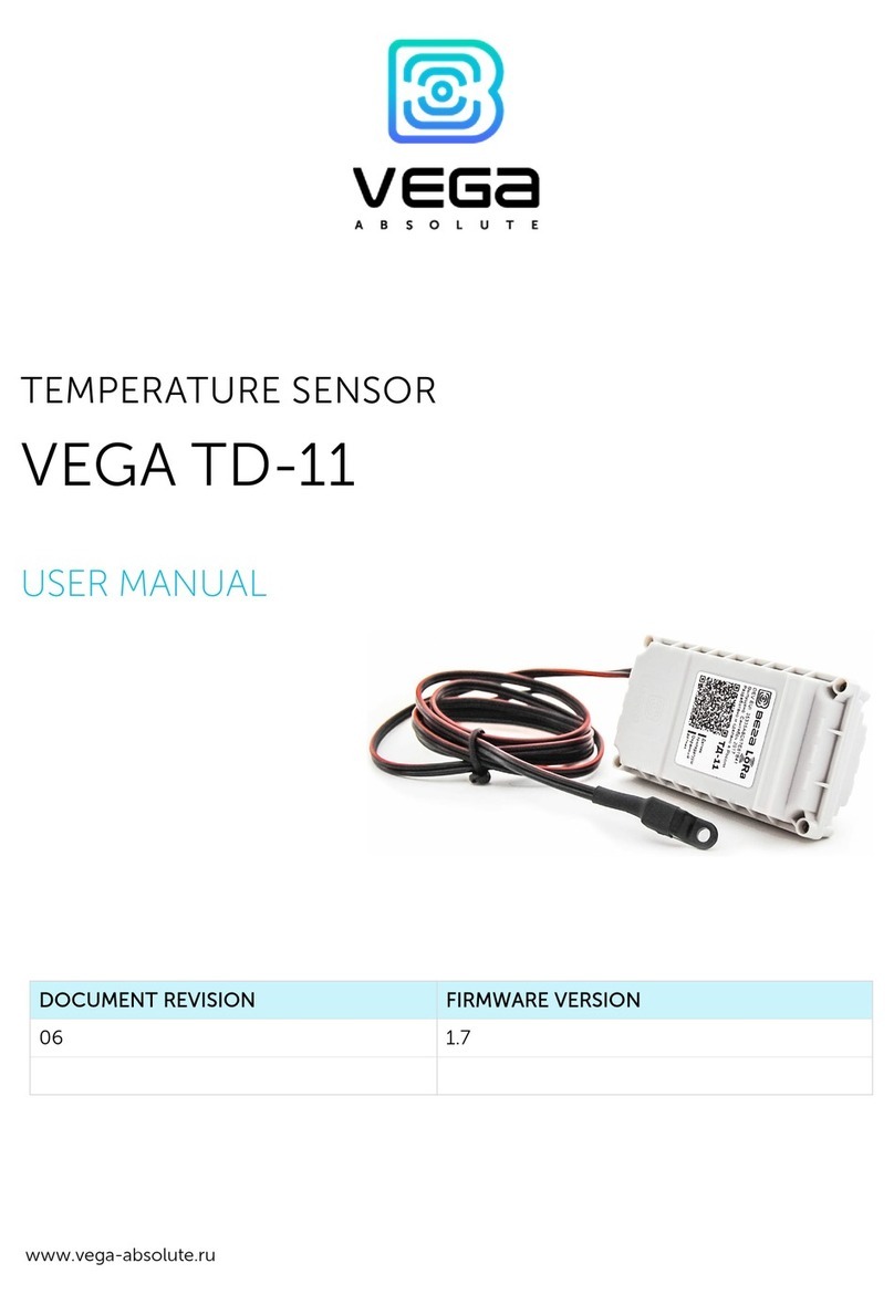
Vega TD-11 is used for measurement air and non-aggressive
gases temperature and further transmitting of this data to the
LoRaWAN network
Vega TD-11 can act as a security sensor and send
extraordinary alarm message by the triggering security input

Vega TD-11 / User Manual
2
Revision 05 - 10 June 2019
Document Information
Title
Vega TD-11 temperature sensor
Document type
Manual - Translation from Russian
Document number
V02-TD11-01
Revision and date
05 –10 June 2019
This document applies to the following products:
Product name
Type number
End devices
Vega TD-11
Revision History
Revision
Date
Name
Comments
01
14.09.2017
KEV
Document creation date
02
13.03.2018
KEV
Changes in specification
03
22.01.2019
TII,
KEV
Changes in specification, in communication protocol, in
device operation logic, in warranty, “Marking” part added
04
24.01.2019
KEV
Inaccuracy in communication protocol fixed –packet
type for packets with settings and request of settings
05
10.06.2019
KEV
Settings 80 and 81 corrected

Vega TD-11 / User Manual
3
Revision 05 - 10 June 2019
CONTENTS
INTRODUCTION............................................................................................................................................................................4
1 DESCRIPTION AND OPERATION ............................................................................................................................................5
2 SPECIFICATION ..........................................................................................................................................................................5
3 OPERATION.................................................................................................................................................................................9
Contacts ......................................................................................................................................................................................9
Device sensors .........................................................................................................................................................................10
Indication ..................................................................................................................................................................................12
Initial startup.............................................................................................................................................................................13
Connecting via USB ................................................................................................................................................................14
4 VEGA LORAWAN CONFIGURATOR......................................................................................................................................16
Interface of the application ...................................................................................................................................................16
Connection to the device......................................................................................................................................................17
“Device info” tab ......................................................................................................................................................................18
“LoRaWAN settings” tab .........................................................................................................................................................20
«Vega TD-11» TAB...................................................................................................................................................................25
5 COMMUNICATION PROTOCOL ...........................................................................................................................................27
Converter TD-11 transmits the following types of packets............................................................................................27
6 STORAGE AND TRANSPORTATION REQUIREMENTS ......................................................................................................31
7 CONTENT OF THE PACKAGE ................................................................................................................................................32
8 WARRANTY................................................................................................................................................................................33

Vega TD-11 / User Manual
4
Revision 05 - 10 June 2019
INTRODUCTION
This manual is designated for Vega TD-11 device (hereinafter –device, converter)
manufactured by Vega-Absolute LLC and provides information on powering and activation
procedure, control commands and functions of the device.
This manual is targeted at specialists familiar with installation work fundamentals for
electronic and electrical equipment.
The device shall be installed and adjusted by qualified specialists in order
to ensure proper operation of the device

Vega TD-11 / User Manual
5
Revision 05 - 10 June 2019
1 DESCRIPTION AND OPERATION
The device Vega TD-11 is designed for measurement atmosphere temperature (air and
non-aggressive gases) by the external thermistor and further transmitting of this data to the
LoRaWAN network.
Also, device can act as a security sensor and send extraordinary alarm message by the
triggering security input.
There is a function of temperature range control in the device. During device setting,
you may set allowed temperature low and high thresholds. When temperature measurements
are out of specified temperature range then extraordinary communication session appears.
Data collection periods when measurements in temperature range and out are set
independently.
Vega TD-11 may be used in systems where temperature control is required but its
directly measurement is difficult. For example, car engine temperatures control and
temperature control at the production rooms, stocks.
TD-11 is powered by a 3400 mAh built-in battery with service life up to 10 years,
provided data transmitted once a day.
The device is powered by a non-rechargeable lithium-thionyl chloride
(LiSOCl2) battery
Attempts to charge the battery may result in fire
COMUNICATION AND DATA COLLECTION ALGORITHM
The readings collecting from the thermistor with a configurable period from 5 minutes
to 24 hours. The readings stored in the device memory and transmitting during the next
communication session with the LoRaWAN network.

Vega TD-11 / User Manual
6
Revision 05 - 10 June 2019
Data collection period when measurements are out of specified temperature range set
independently and may be equal from 5 minutes to 24 hours.
The adjustable data transfer period can be from 5 minutes to 24 hours. Data
transferring in random point in time during set period. At the next communication session, the
device starts sending accumulated packets with readings, from the earliest to the latest.
When measurements are out of specified temperature range the communication
period still the same if parameter “Immediately send data when temperature is out of range” is
not active. If that parameter is active then the alarm message will forming and sending during
2 minutes after the moment of temperature measurements are out of specified range. Every
following message, which will form according to the data collection period, also will have
sent immediately until the temperature measurements are back in range.
With the "Confirmed uplinks" option turned on, the device will send the next packet
only after receiving a confirmation of the delivery of the previous one. If such confirmation
have not received after the fulfilled in the settings uplink number of transmission, device
completes the communication session until the next one according to the schedule. In this
case, the device continues to collect data according to the data collection period and store it
in memory. Non-transmitted packets remain in the device memory until the next
communication session.
With the "Confirmed uplinks" option turned off, the device just sends all accumulated
packets to the network in order from the earliest to the latest. There are no checks of package
delivery in this mode. There are no non-transmitted messages in the device memory.
The internal clock is set automatically when device connected to the "Vega LoRaWAN
Configurator" via USB, also adjustable via LoRaWAN.
FUNCTIONAL
Vega TD-11 temperature sensor is class A device (LoRaWAN classification) and has the
following features:
oTemperature measurement in range of -55… +100 °С
oCharge measuring of the built-in battery (%)
oExtra communication in case of security inputs actuation
oExtra communication in case of tamper sensor actuation
oExtra communication in case of Hall sensor (1 or 2) actuation
oExtra communication in case of temperature measurements are out of specified
range
oTwo operating modes –Active mode and Storage mode
oADR support (Adaptive Data Rate)
oSending of confirmed packets (configurable)
oAbility to configure security input triggering on short, open or both of this cases

Vega TD-11 / User Manual
7
Revision 05 - 10 June 2019
oAbility to set different data collection period for case of temperature
measurements are out of specified range
oImmediately data sending at moment of message forming for case of
temperature measurements are out of specified range
MARKING
Device marked with sticker that contain the next information:
oDevice model;
oDevEUI;
oMonth and year of manufacture;
oQR-code containing DevEUI for automatized count.
Sticker located in three places –on device case, in factory certificate and on the packing
box.
Besides, there is an additional sticker located on the packing box and contains:
oInformation about firmware version;
oQR-code containing DevEUI and keys for device registration in network via
OTAA method.

Vega TD-11 / User Manual
8
Revision 05 - 10 June 2019
2 SPECIFICATION
Main
USB-port
mini-USB, type B
Operating temperatures
-40…+85 °С
Measurement temperatures
-55…+100 °С
Hall sensor sensitivity
5 mT, bipolar
External temperature sensor type
B57861-S 103-F40 10 kOhm
Accuracy of temperature measurement
±0.5 ºСin range -10…+40 ºС
±1 ºСin range -55…+100 ºС
LoRaWAN
AppEui by default
7665676174643131
LoRaWAN class
A
Quantity of LoRa channels
16
Frequency plan
RU868, EU868, IN865, AS923, AU915,
KR920, US915, KZ865, custom (EU868
based)
Activation type
ABP or OTAA
Communication period
5, 15, 30 minutes, 1, 6, 12 or 24 hours
Data collection period
5, 15, 30 minutes, 1, 6, 12 or 24 hours
Memory amount for storing packets
200 packets
Antenna type
internal
Sensitivity
-138 dBm
Radio coverage in restrained urban conditions
up to 5 km
Radio coverage within line of sight
up to 15 km
Transmitter power by default
25 mW (configurable)
Maximum transmitter power
100 mW
Power
Built-in battery
3400 mAh
Warranty number of packets sent by the device,
not less
80 000
Case
Housing dimensions
95 х 50 х 45 mm
Ingress protection rating
IP65
Tamper sensor
yes
Mounting
clamp fastening to the support, DIN-
rail, wall-mounting

Vega TD-11 / User Manual
9
Revision 05 - 10 June 2019
3 OPERATION
CONTACTS
Temperature sensor has a two contact pairs. One pair (“Therm” and “ ” contacts) is for
connect to external thermistor, another one is security input (“Drv” and “Sens” contacts).
Security input of the device can be used for connect to circuits with the following types
of NO contacts:
- reed switch (Herkon);
- mechanical pushbutton;
- open-drain output.
Polarity is matter only for open-drain circuit. Open drain output must be connected to
“Drv” contact and ground to “Sens”.
Security input can trigger on short, open or both of these cases. It is configured by the
“Vega LoRaWAN Configurator” application (See part 4). Should the security input triggering,
the device is activated and sends an alarm message to the network.
When thermistor connecting you should to configure sending data parameters in
“Vega LoRaWAN Configurator” application.
External thermistor
connection
contacts
Contact pair for
connection with
the security circuit

Vega TD-11 / User Manual
10
Revision 05 - 10 June 2019
DEVICE SENSORS
Two Hall sensors are located on the board bottom. Hall sensor triggers in the presence
of magnetic field what allows using temperature sensor for reed switch control. Should the
any sensor triggering, the device sends a corresponding message to the LoRaWAN network
(see part 5).
Tamper is located on the board top. Should the tamper triggering, the device sends a
corresponding message to the LoRaWAN network.
DVR1 –Hall
sensor 1
DVR2 –Hall
sensor 2

Vega TD-11 / User Manual
12
Revision 05 - 10 June 2019
INDICATION
The device has one red LED located on the board. Indication is only used during device
activation step in the LoRaWAN network and when operation modes are switch.
LED signal
Meaning
Series of short flashes
Connection to the network is proceed
One long flash
The device connected to the network
and is in active mode
Three long flashes
Linking to the network is unsuccessful
or the device switched to the «Storage»
mode
In case of connection attempt fail, the device will continue to
accumulate data and will attempt to connect to the network every 6
hours
LED location on
the board

Vega TD-11 / User Manual
13
Revision 05 - 10 June 2019
INITIAL STARTUP
Vega TD-11 is constantly on, but can operate in a special "Storage" mode, designed for
storage and transportation. The device does not regularly transmit data to the network in this
mode. Before use switch the sensor from the “Storage” mode.
The temperature sensor supports two activation methods in the LoRaWAN network -
ABP and OTAA. Select one of the methods using “Vega LoRaWAN Configurator” application
(See part 4).
1. ABP. After pressing the start button, the device immediately starts working in the
"Active" mode.
2. OTAA. After pressing the start button, the device makes three attempts to connect to
the network within the set frequency plan. After the activation in the LoRaWAN network is
confirmed, the device sends a signal (LED flashing for 5 seconds) and switches to the "Active"
mode. If all attempts fail, the device will continue to accumulate data and will attempt to
connect to the network every 6 hours.
To transfer the device from the "Active" mode to the "Storage" mode, you can use the
long press of the start button (more than 5 seconds).
Press the start
button located on
the board

Vega TD-11 / User Manual
14
Revision 05 - 10 June 2019
CONNECTING VIA USB
Vega TD-11 adjusted with the "Vega LoRaWAN Configurator" application (See part 4).
Before connecting the device to the computer for the first time, you must install the
driver for the COM port stsw-stm32102, which can be downloaded from iotvega.com. After
running the executable file VCP_V1.4.0_Setup.exe, the installer window will appear:
USB port is located
on the board

Vega TD-11 / User Manual
15
Revision 05 - 10 June 2019
In this window, you need to click Next, then Install, and then the installation will begin.
When the installation is completed successfully, the following screen appears:
After pressing Finish the driver is ready for operation, - it is possible to connect the
device via USB.

Vega TD-11 / User Manual
16
Revision 05 - 10 June 2019
4 VEGA LORAWAN CONFIGURATOR
The "Vega LoRaWAN Configurator" application (hereinafter referred to as the
configurator) is intended for setting up the device via USB.
The configurator has two modes of operation - "Simple" and "Expert". In the "Simple"
mode, only basic settings are available. In the "Expert" mode, the basic settings, advanced
settings and the ability to check the coverage area of the signal from the gateways are
available. Next, the work of the application is considered in the “Expert”mode.
INTERFACE OF THE APPLICATION
The "Vega LoRaWAN Configurator" application does not require the special installation.
When the executable file is launched, the window for working with the application appears.
The menu on the left allows you to switch between the “Simple”and “Expert”modes,
select the device model, connect to the device or disconnect from it, get and apply settings.
The application window contains three tabs –device info, LoRaWAN settings and
device settings.
The language selection menu is in the upper right corner.

Vega TD-11 / User Manual
17
Revision 05 - 10 June 2019
CONNECTION TO THE DEVICE
For the connection to the device, perform the following steps:
1. Connect the USB cable to the device.
2. Start the "Vega LoRaWAN Configurator" application.
3. Click the "Connect" button in the menu on the left.
The application automatically recognizes the type of device, and the device selection
menu becomes inactive.
To read the settings from the device, you need to click the "Get settings" button, until
this point the application will display the default settings or from the last connected device.
After making the necessary changes to the settings, you should click the "Apply
settings" button and only then disconnect from the device with the "Disconnect" button.

Vega TD-11 / User Manual
18
Revision 05 - 10 June 2019
“DEVICE INFO” TAB
The "Device info" tab displays information about the device, its status, and the data
needed to register the device in the LoRaWAN network.
ABP info - displays the data necessary to register the device in the LoRaWAN network
with ABP method (Activation By Personalization).
OTAA info - the data required to register the device in the LoRaWAN network with
OTAA method (Over The Air Activation) is displayed.
Regional info (not displayed in the "Simple" mode) - shows the frequencies of the JOIN
channels and the second receiving window. These frequencies can be changed in the
"LoRaWAN Settings" tab when selecting a frequency plan.
Device info - the configurator reads information about the device model, its firmware
and automatically corrects the device's time when connected to it.
Update firmware - allows you to select the firmware file from your computer's hard
drive and load it into the device. The device will automatically disconnect from the
configurator when the download is complete. The current version of the device firmware can
be downloaded from iotvega.com.
Network info - shows whether the device is connected to the LoRaWAN network and
its network address.
Join network button - launch the LoRaWAN network connection procedure with the
previously selected ABP or OTAA method. If the device is already connected to the network,
reconnection procedure will occurs.

Vega TD-11 / User Manual
19
Revision 05 - 10 June 2019
Link check (not displayed in the "Simple" mode) - when pressed, the device sends a
special signal to the LoRaWAN network, in response to which the network informs it of the
number of gateways that received this signal and the signal quality. This button only works
when the device is connected to the network.
Device output (not displayed in the "Simple" mode) - monitoring the device status, all
events in real time are displayed.

Vega TD-11 / User Manual
20
Revision 05 - 10 June 2019
“LORAWAN SETTINGS” TAB
The "LoRaWAN Settings" tab allows you to configure various parameters of the LoRa
network.
Region - allows you to select RU-868, EU-868 or specify a custom frequency plan.
In the device frequency plan, only those channels are active by default, on which
sending requests for connection to the network (join channels). The remaining channels (that
the device should use) can be transferring by the LoRaWAN network server during the device
activation procedure (only OTAA).
If you select "Custom" in the "Region" field, you must manually specify the frequencies
that the device will use. To do this, click the "Edit" button, the channel frequency editing
window will appear:
Other manuals for VEGA TD-11
1
Table of contents
Other Vega Absolute Temperature Controllers manuals
Popular Temperature Controllers manuals by other brands

BriskHeat
BriskHeat Centipede 2 instruction manual

Greystone Energy Systems
Greystone Energy Systems HATSSO Series installation instructions

Viessmann
Viessmann Vitotrol 100 UTDB-RF2 Installation and service instructions

Euroclima
Euroclima Radiotactil user manual

Vector
Vector TLC-BCR-T manual

Glas-Col
Glas-Col LimiTrol 104A PC512 User instructions