NewSonic SonoDur-R User manual
NewSonic SonoDur-R Issue 04 Aug/2015 Page 1
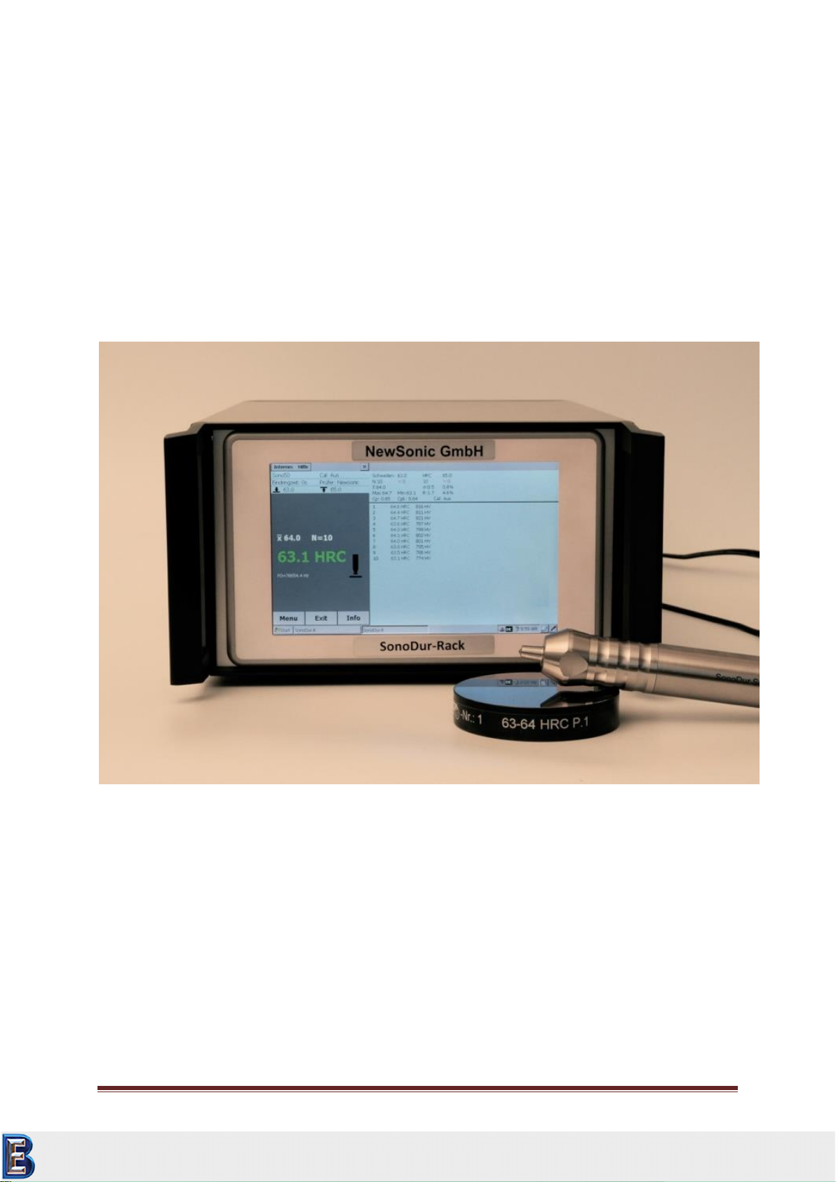
SonoDur-R Instruction Manual
Automated UCI-Hardness Testing System
with
Motorized and Hand-Held Probes
This issue 4, 08/2015 applies to software version V2.16 and higher,
SonoDur-R.
Subject to technical alterations.
Your Complete Source for
Testing Equipment. Since 1969!
www.BergEng.com
Berg Engineering & Sales Company, Inc.
847-577-3980

NewSonic SonoDur-R Issue 04 Aug/2015 Page 2
1 Table of Contents
1 Table of Contents ............................................................................................................................ 2
2 Introduction..................................................................................................................................... 6
2.1 Measuring Method.................................................................................................................. 6
2.2 Safety Information................................................................................................................. 10
2.3 Meaning of “Attention” and “Please note”........................................................................... 10
2.4 Hardness Testing Requirements............................................................................................ 11
3 Measurement Components .......................................................................................................... 11
3.1 Device Connections ............................................................................................................... 12
3.2 Initial Commissioning ............................................................................................................ 13
4 Supply Input Voltage ..................................................................................................................... 13
4.1 Power Supply Connector (PSC)...................................................................................... 13
5 Turning On and Off........................................................................................................................ 14
6 Connect and Disconnect Probe ..................................................................................................... 15
6.1 Connect Probe....................................................................................................................... 15
6.2 Disconnect Probe .................................................................................................................. 15
6.3 Removing Probe Connector during Operation...................................................................... 16
6.4 Operating without Probe –Simulation Mode....................................................................... 16
7 Operation ...................................................................................................................................... 17
7.1 Control Elements................................................................................................................... 17
7.1.1 Operating Structure....................................................................................................... 17
7.1.2 Description of Control Elements ................................................................................... 18
7.2 Soft Keys:............................................................................................................................... 18
7.3 Entries via System Keyboard or SonoDur-R Keyboard .......................................................... 19
7.4 Main Menu Measurement .................................................................................................... 21
7.4.1 Carrying out of Measurement by Means of Motorized Probes .................................... 21
7.4.1.1 Automatic Measurement with Probe Shoe and Switching Sleeve:............................... 21
7.4.1.2 Manual Measurement without Switching Sleeve: ........................................................ 23
7.4.2 Performing a Measurement by Means of Hand-held Probes ....................................... 25
7.5 Information Menu ................................................................................................................. 27
7.6 Instrument Menu .................................................................................................................. 28
7.7 Calibration ............................................................................................................................. 29
7.7.1 Adjust Measurement Value........................................................................................... 29
7.7.2 Adjustment Number Directly ........................................................................................ 32
Your Complete Source for
Testing Equipment. Since 1969!
www.BergEng.com
Berg Engineering & Sales Company, Inc.
847-577-3980

NewSonic SonoDur-R Issue 04 Aug/2015 Page 3
7.7.3 Delete Calibration.......................................................................................................... 33
7.7.4 Save and Load Calibration ............................................................................................. 33
7.8 Conversion............................................................................................................................. 35
7.8.1 Hardness Scale............................................................................................................... 35
7.8.2 Standard ........................................................................................................................ 35
7.8.3 Material ......................................................................................................................... 35
7.9 Measurement Results ........................................................................................................... 36
7.10 Settings.................................................................................................................................. 36
7.10.1 Thresholds ..................................................................................................................... 36
7.10.2 Penetration Time:.......................................................................................................... 37
7.10.3 Tester............................................................................................................................. 38
7.11 SonoDur-R Data Handling...................................................................................................... 39
7.11.1 Store File........................................................................................................................ 39
7.11.2 Open File........................................................................................................................ 40
7.12. Data Transfer and Interfaces................................................................................................. 41
7.12.1 USB Cable ...................................................................................................................... 41
7.12.4 SD (Data Card) Operation.............................................................................................. 41
8 Functional Monitoring by the Operator........................................................................................ 42
8.1 Software Version ................................................................................................................... 42
8.2 Error Messages...................................................................................................................... 43
8.3 Troubleshooting .................................................................................................................... 44
9 Care and Maintenance .................................................................................................................. 45
9.1 Test Device, Probe and Cable................................................................................................ 45
9.2 Screen.................................................................................................................................... 45
10 System ....................................................................................................................................... 46
10.1 System Settings ..................................................................................................................... 46
10.2 Display Backlight.................................................................................................................... 46
10.4 Adjust Touch Screen.............................................................................................................. 46
10.5 Virtual Keyboard.................................................................................................................... 46
10.6 Installing Interfaces and Drivers............................................................................................ 47
10.6.1 USB Installation ............................................................................................................. 47
11 Connectors and Electrical Specification .................................................................................... 49
11.1 Position of Connectors .......................................................................................................... 49
11.2 Power Supply Connector....................................................................................................... 49
11.3 Probe Connector ................................................................................................................... 49
Your Complete Source for
Testing Equipment. Since 1969!
www.BergEng.com
Berg Engineering & Sales Company, Inc.
847-577-3980

NewSonic SonoDur-R Issue 04 Aug/2015 Page 4
11.4 Digital Input / Output signals ................................................................................................ 50
11.4.1 Technical data input/outputs........................................................................................ 50
11.4.2 Pin Description .............................................................................................................. 50
11.4.3 Signal Flow Chart Outputs............................................................................................. 52
11.5 Serial Interface ...................................................................................................................... 52
11.5.1 Remote Control Commands .......................................................................................... 53
12 Appendix.................................................................................................................................... 56
12.1 Scope of Delivery and Accessories ........................................................................................ 56
12.1.1 Standard parts and packages ........................................................................................ 56
12.1.2 Probes............................................................................................................................ 56
12.1.3 Recommended Accessories........................................................................................... 57
12.1.4 Replacement Parts ........................................................................................................ 57
12.1.5 Hardness Reference Blocks ........................................................................................... 57
12.2 Technical Data –SonoDur-R.................................................................................................. 59
12.3 Hardness Scales and Limits.................................................................................................... 60
12.4 Formulas and Terms.............................................................................................................. 61
12.5 Compliance with Environmental Constraints........................................................................ 64
12.6 Limited Warranty .................................................................................................................. 64
13 Accessories ................................................................................................................................ 65
13.1 SONO-PM-4, Prisms Attachment Kit for Motorized Probes.................................................. 65
13.1.1 Technical Data and Components................................................................................... 65
13.1.2 Handling........................................................................................................................ 66
14 Glossary ..................................................................................................................................... 68
15 Addresses .................................................................................................................................. 69
Your Complete Source for
Testing Equipment. Since 1969!
www.BergEng.com
Berg Engineering & Sales Company, Inc.
847-577-3980

NewSonic SonoDur-R Issue 04 Aug/2015 Page 5
Attention:
WARNING:
Before using the device, please read the following manual carefully, including
safety instructions, provided in Section 2.2 Safety Information, Page 10.
Attention:
WARNING:
SonoDur-R starts automatically when switching on the instrument. After this
any manipulation outside of the SonoDur operating panel will be detected and
indicated as system error and Alarm level is set. Changes in system folders for
instance can cause total failure of the whole measurement system and
consequently will lead to loss of any warranty claims.
Your Complete Source for
Testing Equipment. Since 1969!
www.BergEng.com
Berg Engineering & Sales Company, Inc.
847-577-3980

NewSonic SonoDur-R Issue 04 Aug/2015 Page 6
2 Introduction
This instruction manual describes the SonoDur-R hardness tester with motorized and hand-held
probes for automated UCI hardness testing (Ultrasonic Contact Impedance). The SonoDur-R is an
instrument for integration with automated test equipment. SonoDur-R uses the same intuitive
operation scheme as the portable SonoDur Plus.
2.1 Measuring Method
The hardness measurement by means of ultrasonic indirectly evaluates the indentation testing of the
Vickers diamond and digitally displays the result immediately. The application of force can be
implemented either motor-driven or manually against a spring. A hardness value is calculated at a
defined force (penetration force), which correlates to the area of impression after indentation,
although the measurement was carried out under load.
The UCI hardness testing is standardized according to ASTM A 1038, DIN 50159-1 and -2 and
described in VDI / VDE Standards 2616, Sheet 1.
Thereby, it must be noted that the measurement result also depends, for instance, on the elastic
properties of the test material and therefore, the measurement device must be calibrated onto the
test material. Hence, the UCI hardness testing is representing a comparative method attributed to
reference standards (calibrated or adjusted by the operator). The Vickers units (HV) are the reference
scale for the hardness testing. Calibration can be indirectly performed on hardness reference blocks
or directly via comparative measurement, for instance, by means of a Vickers machine (identical test
force) on a specimen of the test material.
If a different test method is being used (Rockwell, Brinell, etc.), shape and material of the indenter,
indentation size and hence, the measuring range varies. Therefore, depending on the material,
treatment and surface condition, calibration or conversion of hardness values can be incorrect or
inadmissible with one another as well as with tensile strength values.
Conversions from the calculated Vickers hardness values are therefore permitted with restrictions
and only in accordance with relevant standards. All conversion tables in accordance with EN ISO
18265, ASTM E 140 are defined in the SonoDur-R instrument. However, the responsible individual
has to make the decision himself on the admissibility of a conversion from the calculated Vickers
hardness on the basis of his specific requirements and experiences.
Motorized probes:
Based on the very low test forces between 1 N (HV0, 1) and 8.6 N (HV1), the measurements are
virtually non-destructive at almost constantly low dispersion of measured values, even at high hard-
ness levels. Thus, the main applications for motorized probes, are production control and
maintenance checks of smooth (polished, lapped) and thereby also coated surfaces (hard chrome,
copper), such as rollers, rotogravure cylinders, automotive components and other components. They
are associated with high-level requirements pertaining to a clean and undamaged material surface. It
is also very well possible to measure small spring components or other precious components, if a
possible component vibration can be suppressed by holding or fastening the device properly.
Your Complete Source for
Testing Equipment. Since 1969!
www.BergEng.com
Berg Engineering & Sales Company, Inc.
847-577-3980

NewSonic SonoDur-R Issue 04 Aug/2015 Page 7
Handheld probes:
With, for instance, test forces of 10N (HV1), 50N (HV 5) and 100N (HV10), handheld probes have
fewer roughness requirements. Therefore, the area of application is wider, also rather tends to very
large and heavy components in hardening plants, for example, after induction hardening, on welding
seams of boilers and pressure pipes. For the cutting edge assessment on structural steel, HV10
measurements have become mandatory as of July 2012 in accordance with EN ISO 1090.
Further applications are described below:
SONO-10H, 10N Test Load (HV1):
In principle, all measurement tasks described under the SONO-8M motorized probe can be
accomplished.
The smaller design enables improved accessibility, i.e. components with more complex geometry can
be measured more easily from all directions –toothed wheels with a smaller number of modules,
forming tools, thin-walled parts.
SONO-50H, 50N Test Load (HV5):
This probe is used most frequently in day-to-day operations, since it can be used not only on thinly
coated components, but also on all components of the above described probes.
There are lower requirements on the surface characteristics than with all probes mentioned above,
which allows testing of more coarse grained materials as well.
In relation between surface condition and manual test force or manual control needed, the
application is very well balanced.
SONO-100H, 98N Test Load (HV10):
Conversions in tensile strength of steel are possible here, for instance on hardened and tempered
steels after flame or induction hardening - according to this standard, it does not apply below HV10 –
in addition, conversions in the range of Rockwell and Brinell testing is more likely, since the surface
portion decreases relative to the volume fraction of the measurement.
Rougher surfaces, such as cold work tool steel for stamping tools, embossing dies and stamps,
forging jaws, sintered metals and high-strength vehicle components, are well suited for HV10
measurements.
Further applications cover weld seam testing, in accordance with HV10 regulation, safety containers,
etc.
Information on the test loads:
In publications and in our documents, the conversion from HV1, HV5, HV10, etc., is sometimes
indicated in rounding numbers due to the conversion factor 1 kp (kgf) = 9.81 N in Newton, N is
sometimes indicated as rounding number (HV 5 = 49N is frequently indicated with 50N and HV10 =
98 N with 100 N). But, the force is precisely adjusted in Newton, thus, for instance: 49N, 98N!
The test conditions in terms of surface characteristics (surface roughness) or layer thicknesses
comply with the requirements of the traditional Vickers hardness measurement. At a HV1
measurement, the UCI standard DIN 50159-1/2 specifies a maximum roughness Ra of <0.5 µm, which
corresponds to in relation to the penetration depth. Accordingly, with HV5, it
comes to 0.8 µm and with HV 10 to 1.0 µm.
Your Complete Source for
Testing Equipment. Since 1969!
www.BergEng.com
Berg Engineering & Sales Company, Inc.
847-577-3980

NewSonic SonoDur-R Issue 04 Aug/2015 Page 8
In this context, penetration depth (d) and average diagonal length (Ld) can be determined by
The table below shows a few examples of the more significant penetration depth (in “µm”]:
Hardness
HV10
HV5
HV1
HV0.3
HV0.1
800 HV
22
15
7
4
2
600 HV
25
18
9
5
2,5
300 HV
36
25
11
6
4
In general, the nature of the component surface in the range of low-load hardness testing, are of
particular importance. High dispersion of measured values can be an indication of excessive surface
roughness. In this case, reworking of the surface with suitable abrasives as well as a re-measurement
may be recommended.
Some other influencing factors are summarized below:
Minimum layer thickness: 10 x d (no noticeable influence by the base material after
calibration)
Minimum material thickness without coupling: > 3 mm (component resonances can falsify
measurement values)
Minimum mass without coupling: > 0.3 kg (component resonances can falsify measurement
values or may make it impossible to perform a measurement)
Minimum distance from the edge of the component edge of the element = 3 x Ld, between
the indentations = 6 x Ld.
Besides surface roughness, material properties such as texture, mechanical tensions, layer structures
and underground also play a role for measurement value variations and deviations from nominal
values.
Above information is by experience where the real practical situation has to be tested on the
material and part in question.
Your Complete Source for
Testing Equipment. Since 1969!
www.BergEng.com
Berg Engineering & Sales Company, Inc.
847-577-3980
NewSonic SonoDur-R Issue 04 Aug/2015 Page 9
The permissible limiting deviations for average values on hardness reference blocks apply in the
assessment of measurement accuracy of UCI devices –refer to table below (from DIN 50159-1/2):
Test Force
Limiting Deviation [%]
< 250 HV
250 HV –500 HV
500 HV –800 HV
> 800 HV
HV 0.1
6
7
8
9
HV 0.3
6
7
8
9
HV 0.8
5
5
6
7
HV 1
5
5
6
7
HV 5
5
5
5
5
HV 10
5
5
5
5
All SonoDur-R probes must meet internal standards with max. ± 3% from 3 -5 measurements on
hardness reference blocks (see 12.2 Technical Data –SonoDur-R, Page 59).
In accordance with the UCI standard DIN 50159-1/2, hardness reference blocks with specific
dimensions are mandatory for the testing, namely a thickness of 16mm and a diameter of 80mm.
These blocks are often hardly obtainable. However, docking the hardness reference block to a flat
hard surface, most preferably made of steel, has much higher significance than the "correct"
dimension. Depending on the support material (wood, cloth, etc.), test force and test position, test
reference blocks can develop macroscopically very complex panel vibrations that can make the
performance of an UCI measurement more difficult or even impossible. Here the widely used
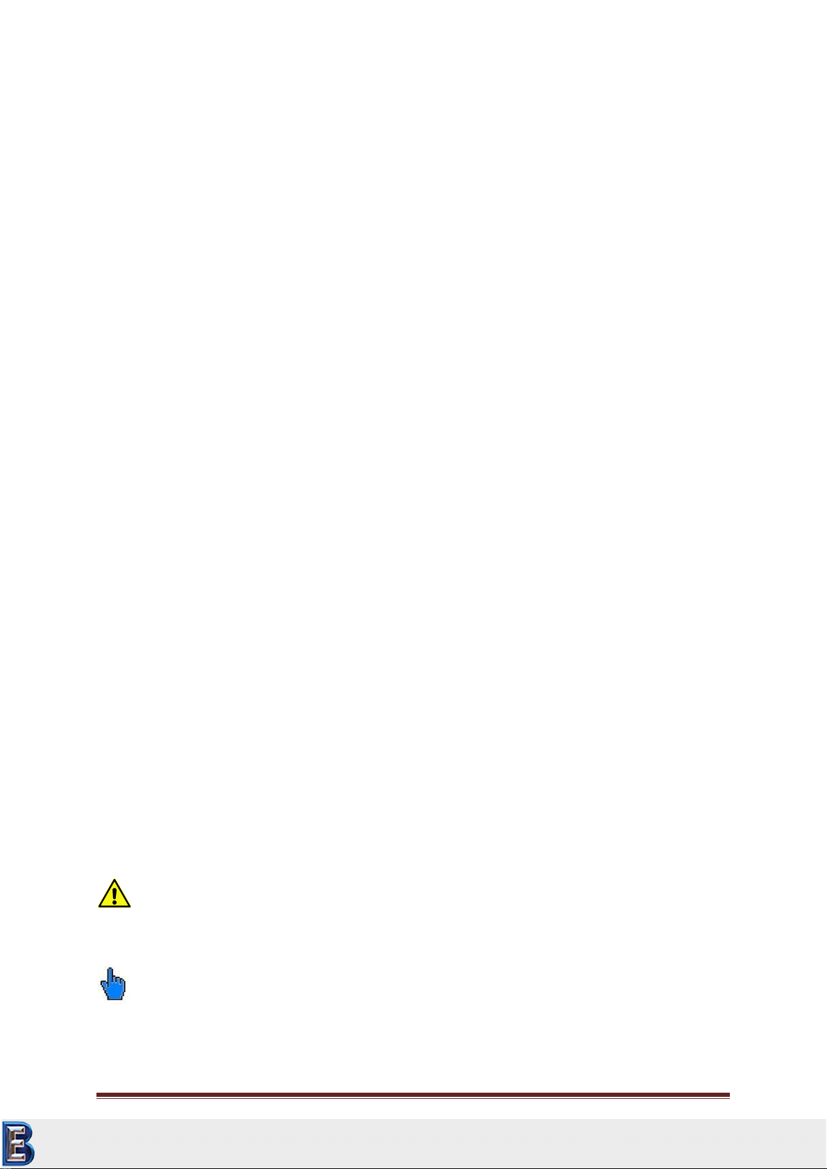
riangular Vickers hardness reference blocks with a thickness of 6 mm (see image below) are very
much prone to panel vibrations and therefore it must definitely be ensured that these are always
well coupled!
Figure 2.1
The best way to derive this type of influence is to observe the ranges of a measurement series.
Depending on the probe and hardness, mean values are furthermore generally more or less
significantly lower or higher than the indications provided on the reference block itself.
Caution is also needed on some Rockwell reference blocks (HRC), if they are only roughly grounded
and therefore depending on the test force, may tend to indicate too low UCI hardness values.
Furthermore special care is to be taken when using hot isostatic pressed blocks are used (applied for
some Leeb-Blocks and Vickers-Blocks) because of local scatter in Hardness or Young’s modulus.
The surface of the test object must be definitely bare, free of surface coverage and scale as well as
liquids. In addition, the test object may not make any movements or vibrations when measurement
is performed.
Attention
These triangle reference blocks need well coupling!
Your Complete Source for
Testing Equipment. Since 1969!
www.BergEng.com
Berg Engineering & Sales Company, Inc.
847-577-3980
NewSonic SonoDur-R Issue 04 Aug/2015 Page 10
During the operation with induction hardening machines, measurements must not be performed
while a high-frequency field is present, since disturbances could occur or the measurement system
may temporarily fail completely.
2.2 Safety Information
The SonoDur-R is manufactured and tested in accordance with the applicable safety regulations (EN
60950-1:2006, EC Low Voltage Directive) and has left the factory in a safety-related flawless
condition. In order to maintain this condition and to ensure safe operation, please make sure you
read the following safety information before you start using the device:
UCI hardness measuring probes are highly accurate precision measurement instruments
which must not under any circumstances, exposed to shocks or impact load!
The device must be exclusively used for material testing, other applications, e.g. medical
applications are not allowed!
Keep measurement devices and accessories out of children’s reach!
The test device and / accessories must no longer be used and need to be secured against
unintentional commissioning, if
ovisible damages are apparent
othe system no longer works properly
othe device had been under extraordinary transportation stress
oafter prolonged storage under extremely unfavorable environmental conditions
(temperature / humidity)
Store and operate the test device and accessory only in the specific environmental conditions
(temperature / humidity)!
When used in commercial facilities, the accident prevention regulations of the professional
trade association for electrical installations and equipment must be observed.
Repairs may only be performed by authorized specialist staff.
Never turn on the device / power supply unit, if the device / accessory is moved from a cold
to a warm area. The generated condensation water may damage the device / accessory
under unfavorable conditions! Leave the device / equipment switched off before it has been
adjusted to room temperature.
2.3 Meaning of “Attention” and “Please note”
Attention
Ignoring these important facts can potentially lead to severe consequences.
Please note
Information provided to make your work easier and to improve results.
Your Complete Source for
Testing Equipment. Since 1969!
www.BergEng.com
Berg Engineering & Sales Company, Inc.
847-577-3980

NewSonic SonoDur-R Issue 04 Aug/2015 Page 11
2.4 Hardness Testing Requirements
An adequate training of operating personnel in the field of material testing is required in order to
perform hardness measurements. This includes, for instance, adequate knowledge of:
General hardness testing
Effect of material characteristics on the hardness testing and selection of the measurement
system
Influence of surface condition
Selection of test force
Understanding about the comparability to other measurement methods, conversion.
Attention:
Lack of knowledge may lead to incorrect test results and cause unforeseeable consequences!
3 Measurement Components
The SonoDur-R consists of a benchtop unit and the herewith connected hardness measuring probe.
The hardness measuring probe can be either a motorized or hand-held probe, equipped with the
relevant features to perform the required measurements. All probes will be attached to the display
unit by USB interface with the cable that is firmly connected to the device. In contrast to other
commonly used devices, the probe is equipped with a microcontroller that already performs the
control system functions, raw data acquisition and signal processing inside the probe.
Hence, the probe can be easily integrated into almost any measurement system via a standard USB
interface.
An overview of the scope of delivery and accessories can be found in the Appendix under Section
12.1 Scope of Delivery and Accessories, Page 56.
Your Complete Source for
Testing Equipment. Since 1969!
www.BergEng.com
Berg Engineering & Sales Company, Inc.
847-577-3980

NewSonic SonoDur-R Issue 04 Aug/2015 Page 12
3.1 Device Connections
Figure 3. 1
Please note:
All connectors are polarized and can only connect to the device plug in one position. When plugging
the cable, it must be ensured that the cable plug is in the correct position towards the device plug (if
necessary, determine by gently rotating it). In this position, the plug can be effortlessly slid by a few
mm into the device plug. Only then, the plug can be clicked into place by pressing it down firmly - but
without using any force. Otherwise, the plug connection may be damaged or destroyed!
For interface definition and electrical data please refer to chapter 11 Connectors and Electrical
Specification, page 49.
Please check the instructions for connecting the probe on chapter 6 Connect and Disconnect
Probe , page 15.
Please make sure that the instructions for connecting the plug connectors are definitely observed!
Attention:
If a plug is forcibly pushed into the connector socket, the entire connector system may be damaged,
resulting in an unusable measurement system.
On / Off
Digital I / O
COM1
COM2
24 VDC
USB
Probe
Your Complete Source for
Testing Equipment. Since 1969!
www.BergEng.com
Berg Engineering & Sales Company, Inc.
847-577-3980

NewSonic SonoDur-R Issue 04 Aug/2015 Page 13
3.2 Initial Commissioning
Each of our products is thoroughly inspected and carefully packed prior to delivery. However, please
check that the shipment is complete and has not been damaged during transportation. (Please see
also Safety Guidelines below).
ATTENTION:
All connectors can only be inserted one way into the jack. Do not, under any circumstances, use force
since the connector system may get damaged.
Connect the instrument to a clean 24 VDC supply voltage source (see section 4 Supply Input Voltage
and section 11 Connectors and Electrical Specification, page 49.
Connect the probe to the instrument, see section 3.1 Device Connections, page 12.
Turn on the device, as described in Section 5 Turning On and Off, Page 14. When the start menu
appears, the unit is ready to perform measurements.
4 Supply Input Voltage
Because of country wise specific trade- and safety marks, the SonoDur-R benchtop instrument does
not have an internal power supply. It just needs a single DC input voltage, please connect the power
supply connector via the SONO-24V cable to a clean DC voltage, we recommend 24 VDC or use our
24 V power supply (order number 11307, see section 12.1 Scope of Delivery and Accessories,
page 56).
4.1 Power Supply Connector (PSC)
The connector is specified according DIN EN 60130-9 (Type C901A 3-pin fem., Amphenol T 3263 000)
View on contact side.
Note: The power input is reversed voltage protected and filtered.
Attention:
Please also observe our Safety Guidelines under Section 2.2 Safety Information, page 10
Pin
Signal Name
Description
Voltage Level
1
Vin
Power supply voltage
12-24 VDC
2
---
Not connected
---
3
GND
Ground
0 V
1
1
Your Complete Source for
Testing Equipment. Since 1969!
www.BergEng.com
Berg Engineering & Sales Company, Inc.
847-577-3980
NewSonic SonoDur-R Issue 04 Aug/2015 Page 14
5 Turning On and Off
The device is turned on / off via the switch (1) on the rear side (see section 3.1 Device Connections,
page 12). Please make sure that all connections are made, the probe is connected and the power
supply can deliver the necessary power.
Please note:
If no probe is connected, the instrument will start in the simulation mode (see section 6.4
Operating without Probe –Simulation Mode, page 16). During the simulation mode, the
instrument will not automatically switch over to regular measurement mode, if a probe is connected.
Please end the program, connect the probe and start the SonoDur-R application again!
If start screen appears, the instrument is ready to take measurements. The middle area of the screen
is the SonoDur-R menu window, the rightmost section is read-only and shows statistic and single
values.
Figure 5. 1
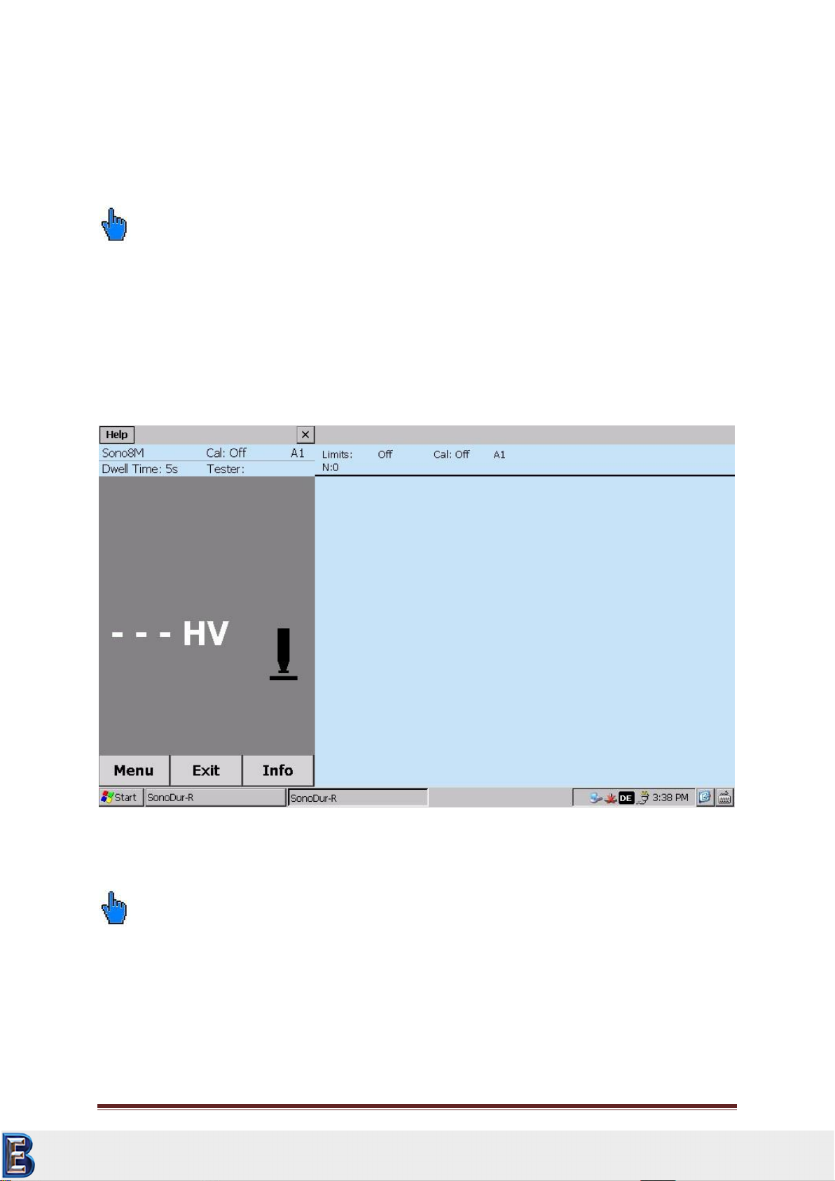
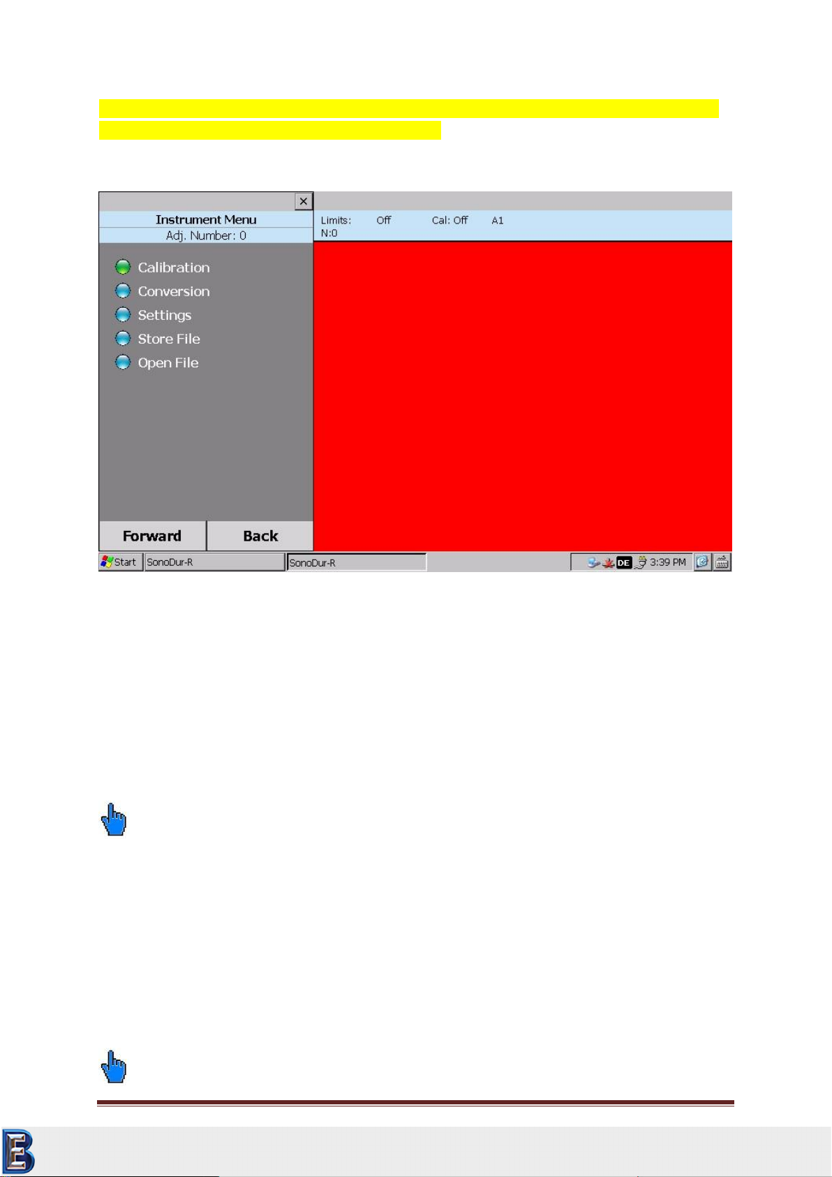
Please note:
If the main window gives up control to another window (this happens p.e. if changing over to a sub
menu, touching to the desktop screen or if an error box appears) the right window area (statistic
window) changes to red and the ALARM output is active. As long as the red window is shown,
SonoDur-R is not in the measuring mode and no measurements can be taken (see figure 5.2)!
In that case, finish your settings und return to the main (measuring) menu. The red window will
change to blue again and SonoDur-R is now ready to take measurements.
Your Complete Source for
Testing Equipment. Since 1969!
www.BergEng.com
Berg Engineering & Sales Company, Inc.
847-577-3980
NewSonic SonoDur-R Issue 04 Aug/2015 Page 15
If you touch by mistake the desktop background, the red window will appear as well. Just touch the
main measuring window to return to measuring mode.
Figure 5.2
6 Connect and Disconnect Probe
The probes are connected with the SonoDur-R through the connection cable that is firmly connected
to the device. The silver metal plug is a locking connector in accordance with the push-pull principle:
When inserting the connector, 3 claws securely lock the connector into the jack. Releasing is only
possible by pulling back the outer sleeve of the plug which releases the locking claws!
Please note:
The connector has a contact arrangement, which allows the connection in only one position.
6.1 Connect Probe
Carefully slide the silver metal plug into the probe socket and rotate until the plug has reached the
correct position and can be smoothly pushed into the socket. Locking is indicated by a "Click". The
connector is now firmly locked with the jack through 3 claws.
6.2 Disconnect Probe
Unlock the silver probe connector by pulling back the sleeve and pulling it out of the jack.
Please note:
Your Complete Source for
Testing Equipment. Since 1969!
www.BergEng.com
Berg Engineering & Sales Company, Inc.
847-577-3980

NewSonic SonoDur-R Issue 04 Aug/2015 Page 16
The probe connector should not be separated from the probe during operation!
6.3 Removing Probe Connector during Operation
If the probe connector is removed during operation, the program SonoDur-R will be closed and can
be called up again by touching the SonoDur start icon on the touch screen. In some unfavorable
cases the system may not recognize the probe and an error message will be generated. In this case
the probe should be disconnected again and the SonoDur-R switched off and on. Afterwards the
probe may be connected then calling the SonoDur-R program.
6.4 Operating without Probe –Simulation Mode
The device is equipped with a special feature when turning it on without a connected probe: The
simulation mode makes it possible to test all functions of the SonoDur-R measurement program,
without having to perform self-measurements with probes.
“Measurement Values" will now be generated by touching the probe symbol and all functions in
connection with the testing procedure can be operated –a special way of fast training for operators
and also to give presentations to all those who are interested.
To return to normal operation connect the probe to SonoDur-R and switch the machine “OFF” and
“ON” and the probe will be automatically detected.
Start program without probe:
Figure 6. 1
Figure 6. 2
Figure 6. 1
Your Complete Source for
Testing Equipment. Since 1969!
www.BergEng.com
Berg Engineering & Sales Company, Inc.
847-577-3980

NewSonic SonoDur-R Issue 04 Aug/2015 Page 17
7 Operation
7.1 Control Elements
The SonoDur-R is operated via touch-sensitive fields on the middle area of the screen ("soft keys“).
These soft keys can be labeled fields, round buttons or symbols, numbers and figures. Except
“Orientation” all other symbols, numbers or figures give direct access to the corresponding menu.
7.1.1 Operating Structure
The SonoDur-R basically
provides two-level operation,
the Measuring Menu (Figure 7.1)
and the Instrument Menu
(Figure 7.3).
1
3
Calibration menu
Dwell Time setting
Threshold setting
Info menu
Hardness scales menu
Start measuring manually,
When using motor probes
Instrument Menu
Exit button
Info menu
Figure 7. 2
Figure 7. 3
Figure 7. 1
Your Complete Source for
Testing Equipment. Since 1969!
www.BergEng.com
Berg Engineering & Sales Company, Inc.
847-577-3980
NewSonic SonoDur-R Issue 04 Aug/2015 Page 18
Attention:
CAUTION! Never use anything other than the stylus on the touch screen. Otherwise this could cause
a permanent damage.
7.1.2 Description of Control Elements
Changeovers between the menus are performed via touch-sensitive menu buttons at the lower edge
of the screen.
Menu
Changeover to the Instrument Menu
Exit
1. Exiting the Measurement Menu, end of the measurement series
2. Exiting any sub-program within the Instrument Menu and changeover into the Measurement
Menu
3. Closing SonoDur-R (after processing the last measuring series and prior to the first new
measurement value).
Info
Display device settings for the measurement process, display of measurement results such as
statistics, single values and corresponding correction possibilities.
Next
Call up “green” highlighted menu item and take one step forward within the sub-menu
Back
Go back one step within the sub-menu
File (within the “Info” sub-menu)
Activating and displaying of stored measurement data.
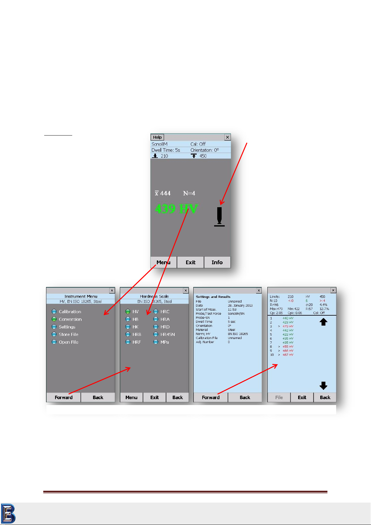
7.2 Soft Keys:
By touching the screen within the Measurement menu, direct changeovers to specific sub-programs
can take place, for instance:
In the Measurement Result field by touching of
“HV“: Change over to the hardness scale selection
“610“ HV, current measurement value with the inquiry, whether the latest measurement
value shall be deleted.
Your Complete Source for
Testing Equipment. Since 1969!
www.BergEng.com
Berg Engineering & Sales Company, Inc.
847-577-3980
NewSonic SonoDur-R Issue 04 Aug/2015 Page 19
Average value “Overline X“: Change over to “Info Menu”, Section 7.5 after processing of
measurement values (analogous to the Info button)
“Indentation Time 5 s“to change the indentation time
“SONO3M“, if a motorized probe is connected (or SONO1M, SONO8M), change over to the
measurement method selection “motor-driven“ or “freehand measurement“
“CAL: Off“: Change over to subprogram “Calibration“
Line indicating the tolerance thresholds (if it has been set): “Thresholds”
“Probe Symbol“, manual initiation of hardness measurement (see measurement process)
“Direction: 0“, correction of measurement direction (is currently still without function)
Examples:
7.3 Entries via System Keyboard or SonoDur-R Keyboard
All entries in input fields requesting numbers be can be done by the SonoDur-R keypad or the system
keypad. The system keypad is located in the bottommost right corner of the screen and can be
“Cal: Off“ Standard Calibration,
Sono8M: motor probe 8,6N Test
Force
“Penetration Time: 5 seconds“
“Direction: 0“, Measurement
Direction (currently still no
function), “210; 450“, lower and
upper tolerance thresholds.
“439“Delete measurement
value?
“HV“ Change hardness scale?
“Overline X 444“(average and
N=4 No. of measurements),
Process measurement values.
Probe Symbol:
Manual initiation of
measurement cycle by touching
the probe symbol
Instrument Control:
Menu = Instrument Menu
Exit = Change over to
“measurement” or “end of
measurement”
Info = Display of settings and
results
File = Displaying stored data
Current evaluations in other hardening scales
in accordance with standard and depending on
connected probe.
“Info“: Settings and Results.
“Forward“: Details, correct individual
measurement errors.
Figure 7. 4
Your Complete Source for
Testing Equipment. Since 1969!
www.BergEng.com
Berg Engineering & Sales Company, Inc.
847-577-3980

NewSonic SonoDur-R Issue 04 Aug/2015 Page 20
activated by clicking on the keypad symbol. If letter symbols are needed (in case of naming data
sets), the system keypad will automatically pop up and disappear, when the entry is finished. The
system keypad can be closed manually by clicking “Hide Input Panel”
Any position inside the input field can be marked, modified or supplemented.
Numbers however should be entered via the large and more user-friendly SonoDur-R keyboard:
Number field, horizontal arrow as Delete key (individual symbols on the left hand side in order to
place the cursor), decimal point or minus sign.
Figure 7. 5
Figure 7. 6
Figure 7. 7
Your Complete Source for
Testing Equipment. Since 1969!
www.BergEng.com
Berg Engineering & Sales Company, Inc.
847-577-3980
Table of contents
Other NewSonic Test Equipment manuals


