NewSonic SonoDur2 User manual
NewSonic SonoDur2 Issue 04 09/2016 Page 1
SonoDur2 Instruction Manual
Portable UCI Hardness Testing System
with
Motorized and Hand-held Measuring Probes
This issue 04, 09/2016 applies to software version V1.15 and higher,
SonoDur2.
Subject to technical alterations.
Your Complete Source for
Testing Equipment. Since 1969!
www.BergEng.com
Berg Engineering & Sales Company, Inc.
Tel 847-577-3980

NewSonic SonoDur2 Issue 04 09/2016 Page 2
Copyright
Copyright 2016 by NewSonic GmbH.
All Rights reserved. No part of this manual may be copied, reproduced or stored in any form without
the prior written permission of NewSonic GmbH, except for personal non-commercial use of the
buyer.
Disclaimer
All information and technical data in this manual or any other documents have been prepared with
great care and believed to be reliable, but the accuracy or completeness thereof is not guaranteed.
NewSonic assumes no responsibility for inaccuracies or omissions and specifically disclaims any
liabilities, losses, or risks, personal or otherwise, incurred as a consequence, directly or indirectly, of
the use or application of any part of this document.
For the latest documentation, please contact your local NewSonic representative or visit us online at
http://www.newsonic.de/
NewSonic reserves the right to make changes without further notice to any product or system to
improve reliability, function or design.
Your Complete Source for
Testing Equipment. Since 1969!
www.BergEng.com
Berg Engineering & Sales Company, Inc.
Tel 847-577-3980

NewSonic SonoDur2 Issue 04 09/2016 Page 3
1Table of Contents
1 Table of Contents ............................................................................................................................ 3
2 Introduction..................................................................................................................................... 7
2.1 Measuring Method.................................................................................................................. 7
2.2 Safety Information................................................................................................................. 12
2.3 Meaning of “Attention” and “Please note”........................................................................... 12
2.4 Hardness Testing Requirements............................................................................................ 13
3 Measurement Components .......................................................................................................... 14
3.1 Device Connections ............................................................................................................... 14
3.2 Initial Commissioning ............................................................................................................ 15
4 Power Supply................................................................................................................................. 16
4.1 Power Supply Unit................................................................................................................. 16
4.2 Exchange Battery Pack .......................................................................................................... 16
4.3 Charging................................................................................................................................. 17
4.4 Operating Time...................................................................................................................... 19
4.4.1 Querying of Battery Capacity ........................................................................................ 19
5 Turning On and Off........................................................................................................................ 20
6 Connect and Disconnect Probe ..................................................................................................... 21
6.1 Connect Probe....................................................................................................................... 21
6.2 Disconnect Probe .................................................................................................................. 21
6.3 Removing Probe Connector during Operation...................................................................... 22
6.4 Operating without Probe –Simulation Mode....................................................................... 22
7 Operation ...................................................................................................................................... 23
7.1 Control Elements................................................................................................................... 23
7.1.1 Operating Structure....................................................................................................... 24
7.1.2 Description of Control Elements ................................................................................... 24
7.2 Soft Keys ................................................................................................................................ 25
7.3 Entries via System Keyboard or SonoDur2 Keyboard ........................................................... 26
7.4 Main Menu Measurement .................................................................................................... 26
7.4.1 Carrying out of Measurement by Means of Motorized Probes .................................... 27
7.4.2 Automatic Measurement with Probe Shoe and Switching Sleeve:............................... 27
7.4.3 Manual Measurement without Switching Sleeve: ........................................................ 29
7.4.4 Performing a Measurement by Means of Hand-held Probes ....................................... 31
7.5 Information Menu ................................................................................................................. 32
Your Complete Source for
Testing Equipment. Since 1969!
www.BergEng.com
Berg Engineering & Sales Company, Inc.
Tel 847-577-3980

NewSonic SonoDur2 Issue 04 09/2016 Page 4
7.6 Device Menu.......................................................................................................................... 33
7.7 Adjustment............................................................................................................................ 33
7.7.1 Adjust Measurement Value........................................................................................... 34
7.7.2 Adjustment Number Directly ........................................................................................ 35
7.7.3 Delete Adjustment ........................................................................................................ 36
7.7.4 Save and Load Adjustment............................................................................................ 37
7.8 Conversions ........................................................................................................................... 38
7.8.1 Hardness Scale............................................................................................................... 38
7.8.2 Standard ........................................................................................................................ 38
7.8.3 Material ......................................................................................................................... 38
7.8.4 Representation of Readings beyond Conversion Limits................................................ 38
7.9 Measurement Results ........................................................................................................... 40
7.10 Settings.................................................................................................................................. 40
7.10.1 Limits (Thresholds) ........................................................................................................ 40
7.10.2 Dwell Time..................................................................................................................... 40
7.10.3 Measurement Mode...................................................................................................... 41
7.10.4 Working with Templates ............................................................................................... 43
7.10.5 Tester............................................................................................................................. 44
7.11 SonoDur2 Data Handling ....................................................................................................... 45
7.11.1 Save Files ....................................................................................................................... 45
7.11.2 Open File........................................................................................................................ 46
7.11.3 Data Transfer and Interfaces......................................................................................... 46
7.11.4 USB Cable ...................................................................................................................... 47
7.11.5 Bluetooth....................................................................................................................... 47
7.11.6 WLAN............................................................................................................................. 48
7.11.7 Data Card Operation...................................................................................................... 48
8 Functional Monitoring by the Operator........................................................................................ 49
8.1 Software Version ................................................................................................................... 49
8.2 Error Messages...................................................................................................................... 50
8.3 Troubleshooting .................................................................................................................... 51
8.3.1 Operating the On/Off Switch......................................................................................... 51
9 Care and Maintenance .................................................................................................................. 52
9.1 Test Device, Probe and Cable................................................................................................ 52
9.2 Screen.................................................................................................................................... 52
9.3 Batteries ................................................................................................................................ 52
Your Complete Source for
Testing Equipment. Since 1969!
www.BergEng.com
Berg Engineering & Sales Company, Inc.
Tel 847-577-3980

NewSonic SonoDur2 Issue 04 09/2016 Page 5
10 System ....................................................................................................................................... 53
10.1 System Settings ..................................................................................................................... 53
10.2 Display Lighting...................................................................................................................... 53
10.3 Automatic Shutdown............................................................................................................. 54
10.4 Adjust Touch Screen.............................................................................................................. 54
10.5 Virtual Keyboard.................................................................................................................... 54
10.6 Installing Interfaces and Drivers............................................................................................ 55
10.6.1 Preparedness................................................................................................................. 55
10.6.2 Connecting SonoDur2 to your Computer...................................................................... 56
10.6.3 Bluetooth Setup............................................................................................................. 57
10.6.4 Transfer Data to the Computer ..................................................................................... 60
10.6.5 WLAN............................................................................................................................. 60
11 Appendix.................................................................................................................................... 61
11.1 Scope of Delivery and Accessories ........................................................................................ 61
11.1.1 Standard parts and packages ........................................................................................ 61
11.2 Technical Data –SonoDur2 ................................................................................................... 65
11.3 Hardness Scales and Limits.................................................................................................... 67
11.4 Formulas and Terms.............................................................................................................. 68
11.5 Compliance with Environmental Constraints........................................................................ 71
11.6 Limited Warranty .................................................................................................................. 71
12 Accessories ................................................................................................................................ 72
12.1 SONO-PM-4, Prisms Attachment Kit for Motorized Probes.................................................. 72
12.1.1 Technical Data and Components................................................................................... 72
12.1.2 Handling......................................................................................................................... 73
13 Glossary ..................................................................................................................................... 75
14 Addresses .................................................................................................................................. 76
Your Complete Source for
Testing Equipment. Since 1969!
www.BergEng.com
Berg Engineering & Sales Company, Inc.
Tel 847-577-3980

NewSonic SonoDur2 Issue 04 09/2016 Page 6
Attention:
WARNING:
Before using the device, please read the following manual carefully, including
safety instructions, provided in section “Safety Information“, page 12.
Your Complete Source for
Testing Equipment. Since 1969!
www.BergEng.com
Berg Engineering & Sales Company, Inc.
Tel 847-577-3980

NewSonic SonoDur2 Issue 04 09/2016 Page 7
2Introduction
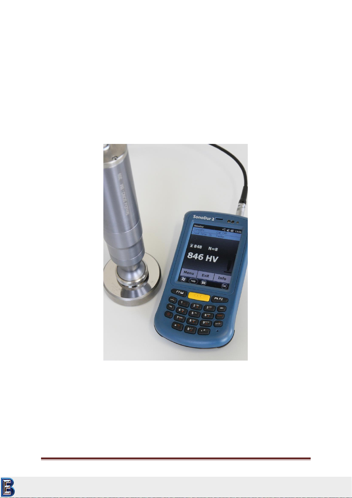
This instruction manual describes the hardness tester SonoDur2 with motorized and hand-held
measuring probes for UCI hardness testing (Ultrasonic Contact Impedance).
2.1 Measuring Method
The hardness measurement by means of ultrasonic indirectly evaluates the indentation testing of the
Vickers diamond and digitally displays the result immediately. The application of force can be
implemented either motor-driven or manually against a spring. A hardness value is calculated at a
defined force (penetration force), which correlates to the area of impression after indentation,
although the measurement was carried out under load.
The UCI hardness testing is standardized according to ASTM A 1038, DIN 50159-1 and -2 and
described in VDI / VDE Standards 2616, Sheet 1.
Thereby, it must be noted that the measurement result depends, among others, on the elastic
properties of the test material and therefore, the measurement device must be calibrated onto the
test material. Hence, the UCI hardness testing is representing a comparative method attributed to
reference standards (calibrated or adjusted by the operator). The reference scale for the hardness
testing is the Vickers unit (HV). Adjustment can be indirectly performed on hardness reference blocks
or directly via comparative measurement, for instance, by means of a Vickers machine (identical test
force) on a specimen of the test material.
If a different test method is being used (Rockwell, Brinell, etc.), shape and material of the indenter,
indentation size and hence, the measuring range varies. Therefore, depending on the material,
treatment and surface condition, adjustment or conversion of hardness values can be incorrect or
inadmissible with one another as well as with tensile strength values.
Conversions from the calculated Vickers hardness values are therefore permitted with restrictions
and only in accordance with relevant standards. All conversion tables in accordance with EN ISO
18265, ASTM E 140 are defined in the SonoDur2 tester. However, it’s up to the responsible individual
to decide about the admissibility of a conversion based on the calculated Vickers hardness on the
basis of his specific requirements and experiences.
Motorized measuring probes: Based on the very low test forces between 1 N (HV0, 1) and 8.6 N
(HV1), the measurements are virtually non-destructive at almost constantly low dispersion of
measured values, even at high hardness levels. Thus, the main applications for motorized probes,
production control and maintenance checks of smooth (polished, lapped) and thereby also coated
surfaces (hard chrome, copper), such as rollers, rotogravure cylinders, automotive components and
other components, are associated with high-level requirements pertaining to a clean and undamaged
material surface. It is also very well possible to measure small spring components or other precious
components, if a possible component vibration can be suppressed by holding or fastening the device
properly.
Hand-held measuring probes with, for instance, test forces of 10N (HV1), 50N (HV 5) and 100N
(HV10), have fewer roughness requirements. Therefore, the area of application is wider, also rather
tends to very large and heavy components in hardening plants, for example, after induction
hardening, on welding seams of boilers and pressure pipes. For the cutting edge assessment on
Your Complete Source for
Testing Equipment. Since 1969!
www.BergEng.com
Berg Engineering & Sales Company, Inc.
Tel 847-577-3980

NewSonic SonoDur2 Issue 04 09/2016 Page 8
structural steel, HV10 measurements will become mandatory as of July 2012 in accordance with EN
ISO 1090.
Further applications are described in the following:
SONO-10H, 10N Test Load (HV1):
In principle, all measurement tasks described under the SONO-8M motorized measuring probe can
be accomplished. The smaller design enables improved accessibility, i.e. it is easier to measure
components with more complex geometry from all directions - toothed wheels with a smaller
number of modules, forming tools, thin-walled parts.
SONO-50H, 50N Test Load (HV5):
This probe is used most frequently in day-to-day operations, since it can be used not only on thinly
coated components, but also on all components of the above described probes.
There are lower requirements on the surface characteristics than with all probes mentioned above,
which allows to test more coarse grained materials as well.
In relation between surface condition and manual test force or manual control needed, the
application is very well balanced.
SONO-100H, 98N Test Load (HV10):
Conversions in tensile strength of steel are possible here, for instance on hardened and tempered
steels after flame or induction hardening - according to this standard, it does not apply below HV10 –
in addition, conversions in the range of Rockwell and Brinell testing is more likely, since the surface
portion decreases relative to the volume fraction of the measurement.
Rougher surfaces, such as cold work tool steel for stamping tools, embossing dies and stamps,
forging jaws, sintered metals and high-strength vehicle components, are well suited for HV10
measurements.
Weld seam testing, in accordance with HV10 regulation, safety containers, etc.
Information on the test loads:
In publications and in our documents, the conversion from HV1, HV5, HV10, etc., is sometimes
indicated in rounding numbers due to the conversion factor 1 kp (kgf) = 9.81 N in Newton, N is
sometimes indicated as rounding number (HV 5 = 49N is frequently indicated with 50N and HV10 =
98 N with 100 N). But, the force is precisely adjusted in Newton, thus, for instance: 49N, 98N!
The test conditions in terms of surface characteristics (surface roughness) or layer thicknesses
comply with the requirements of the traditional Vickers hardness measurement. At a HV1
measurement, the UCI standard DIN 50159-1/2 specifies a maximum roughness Ra of <0.5 µm, which
corresponds to in relation to the penetration depth. Accordingly, with HV5 it
comes to 0.8 µm and with HV 10 up to 1.0 µm.
In this context, penetration depth (d) and average diagonal length (Ld) can be determined by
Equation 2-1
Your Complete Source for
Testing Equipment. Since 1969!
www.BergEng.com
Berg Engineering & Sales Company, Inc.
Tel 847-577-3980
NewSonic SonoDur2 Issue 04 09/2016 Page 9
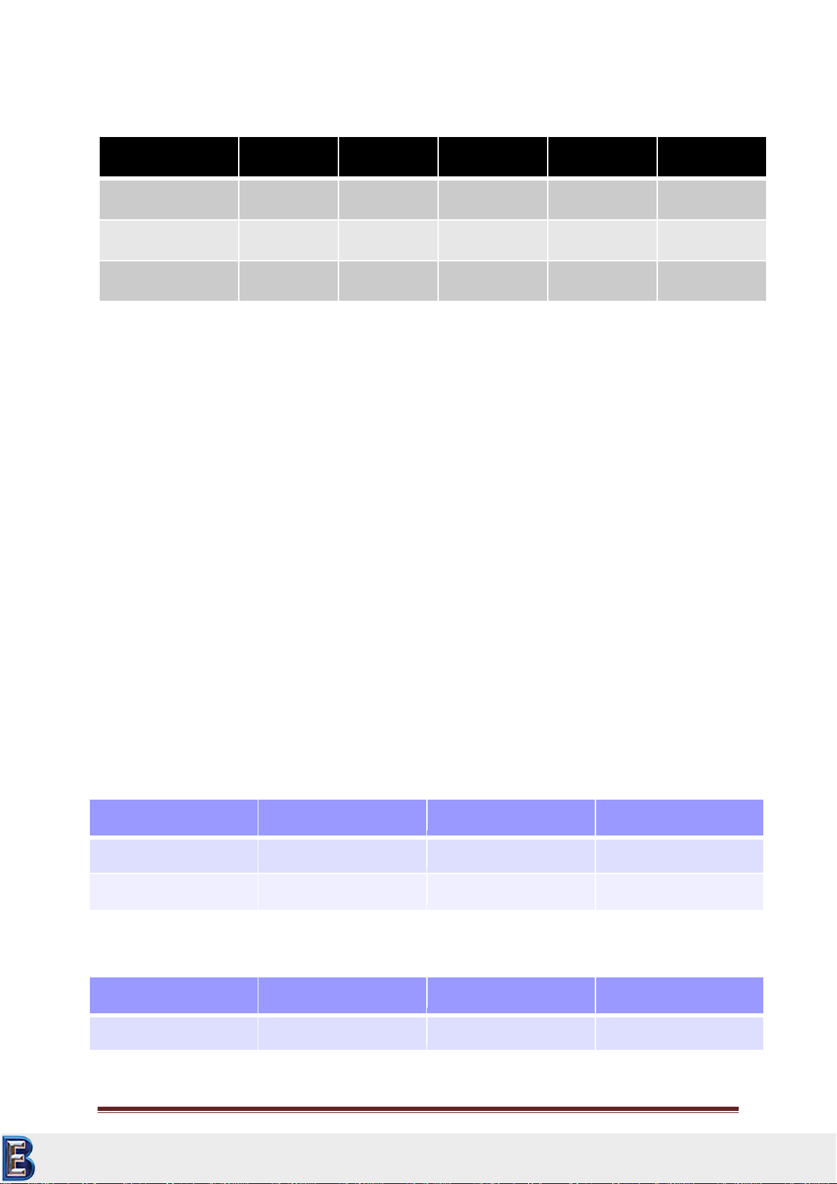
The table below shows a few examples of the more significant penetration depth (in “µm”):
Hardness
HV10
HV5
HV1
HV0.3
HV0.1
800 HV
22
15
7
4
2
600 HV
25
18
9
5
2,5
300 HV
36
25
11
6
4
Table 2-1
In general, the nature of the component surface in the range of low-load hardness testing, are of
particular importance. High dispersion of measured values can be an indication of excessive surface
roughness. In this case, reworking of the surface with suitable abrasives as well as a re-measurement
may be recommended.
Some other influencing factors are summarized in the following:
Minimum layer thickness: 10 x d (no noticeable influence by the base material after
adjustment)
Minimum material thickness without coupling: > 3 mm (component resonances can falsify
measurement values)
Minimum mass without coupling: > 0.3 kg (component resonances can falsify measurement
values or may make it impossible to perform a measurement)
Minimum distance from the component edge of the element = 3 x Ld, between the
indentations = 6 x Ld
The surface roughness should be much less as the penetration depth (< 1/5 x d)
In the latest issue of the German standard DIN 50159-1,2-2015 examples for the required surface
roughness Ra for different test loads and as well for the grit size for the manual grinding work are
given, see tables below:
Testload [N]
10
50
98
Ra [µm]
0,5
0,8
1,0
Ra [µm] ASTM
5
10
15
Tabelle 2-2: Guidelines for the maximum surface roughness according to EN ISO 6507 (Vickers) and
information given in the standard ASTM A 1038
Sand paper grit size
120
180
240
Ra [µm]
1,2
1,0
0,6
Tabelle 2-3: Surface roughness after manual grinding using sand paper with various grit size (FEPA-
Standard, „Federation of the European Producers of Abrasives“).
Your Complete Source for
Testing Equipment. Since 1969!
www.BergEng.com
Berg Engineering & Sales Company, Inc.
Tel 847-577-3980
NewSonic SonoDur2 Issue 04 09/2016 Page 10
Besides surface roughness, material properties such as texture, mechanical tensions, layer structures
and underground also play a role for measurement value variations and deviations from nominal
values.
The above information is based on experience where the real practical situation has to be tested on
the material and part in question.
The permissible limiting deviations for average values on hardness reference blocks apply in the
assessment of measurement accuracy of UCI devices - refer to table below (from DIN 50159-1/2):
Hardness
Scale
Limiting Deviation
%
< 250 HV
250 HV –500 HV
500 HV –800 HV
> 800 HV
HV 0.1
6
7
8
9
HV 0.3
6
7
8
9
HV 0.8
5
5
6
7
HV 1
5
5
6
7
HV 5
5
5
5
5
HV 10
5
5
5
5
Table 2-4
All SonoDur2 probes must meet internal standards with max. ± 3% from 3 -5 measurements on
hardness reference blocks (see Technical Data –SonoDur2, Page 65).
In accordance with the UCI standard DIN 50159-1/2, hardness reference blocks with specific
dimensions are mandatory for the testing, namely a minimum thickness of 15mm and a diameter of
80mm. These blocks are often hardly obtainable. However, docking the hardness reference block to a
flat hard surface, most preferably made of steel, has much higher significance than the "correct"
dimension. Depending on the support material (wood, cloth, etc.), test force and test position, test
reference blocks can develop macroscopically very complex panel vibrations that can complicate the
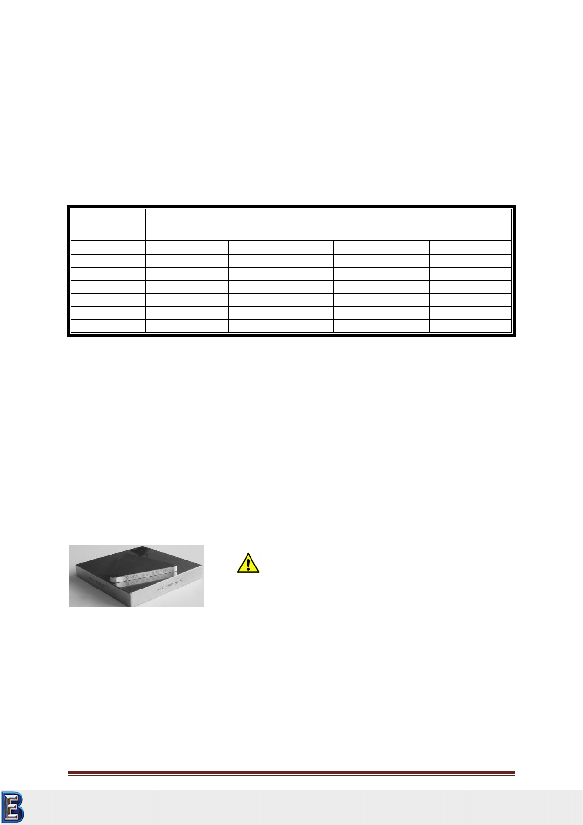
performance of an UCI measurement or make it even impossible. Triangular Vickers hardness
reference blocks with a thickness of 6 mm (see image below) are very much prone to panel vibrations
and therefore it must definitely be ensured that these are always well coupled!
Figure 2.1
The best way to derive this type of influence is to observe the ranges of a measurement series.
Depending on the probe and hardness, mean values are furthermore generally more or less
significantly lower or higher than the indications provided on the reference block itself.
Caution is also needed on some Rockwell reference blocks (HRC), if they are only roughly grounded
and therefore depending on the test force, may tend to indicate too low UCI hardness values.
Attention
These triangle reference blocks need well coupling!
Your Complete Source for
Testing Equipment. Since 1969!
www.BergEng.com
Berg Engineering & Sales Company, Inc.
Tel 847-577-3980

NewSonic SonoDur2 Issue 04 09/2016 Page 11
Furthermore special care is to be taken when using hot isostatic pressed blocks are used (applied for
some Leeb-Blocks) because of local scatter in Hardness or Young’s modulus.
The surface of the test object must be definitely bare, free of surface coverage and scale as well as
liquids. In addition, the test object may not move or vibrate when measurement is performed.
During the operation with induction hardening machines, measurements may must not be
performed while a high-frequency field is present, since disturbances could occur or the
measurement system may temporarily fail completely.
Your Complete Source for
Testing Equipment. Since 1969!
www.BergEng.com
Berg Engineering & Sales Company, Inc.
Tel 847-577-3980

NewSonic SonoDur2 Issue 04 09/2016 Page 12
2.2 Safety Information
The SonoDur2 is manufactured and tested in accordance with the applicable safety regulations (EN
60950-1:2006, EC Low Voltage Directive) and has left the factory in a safety-related flawless
condition. In order to maintain this condition and to ensure safe operation, please make sure you
read the following safety information before you start using the device:
UCI hardness measuring probes are highly accurate precision measurement instruments
which may not, under any circumstances, be exposed to shocks or impact load!
The device must be exclusively used for material testing, other applications, e.g. medical
applications are not allowed!
Keep measurement devices and accessories out of children’s reach!
The SONO-NG plug-in power supply unit may be used in dry areas only! Please do not use a
power supply plug-in adaptor that is not approved for this product!
The test device and/or plug-in power supply may no longer be used and need to be secured
against unintentional commissioning, if
visible damages are apparent
the system no longer works properly
the device had been under extraordinary transportation stress
after prolonged storage under extremely unfavorable environmental conditions
(temperature/humidity)
Store and operate the test device and accessory only in the specific environmental conditions
(temperature/humidity)!
When used in commercial facilities, the accident prevention regulations of the professional
trade association for electrical installations and equipment must be observed.
Repairs may only be performed by authorized specialist staff.
Never turn on the device/power supply unit, if the device/accessory is moved from a cold to
a warm area. The generated condensation water may damage the device/accessory under
unfavorable conditions! Leave the device/equipment switched off before it has been
adjusted to room temperature.
2.3 Meaning of “Attention” and “Please note”
Attention:
Ignoring these important facts can potentially lead to severe consequences.
Please note
Information provided to make your work easier and to improve results.
Your Complete Source for
Testing Equipment. Since 1969!
www.BergEng.com
Berg Engineering & Sales Company, Inc.
Tel 847-577-3980

NewSonic SonoDur2 Issue 04 09/2016 Page 13
2.4 Hardness Testing Requirements
An adequate training of operating personnel in the field of material testing is required in order to
perform hardness measurements. This includes, for instance, adequate knowledge of:
General hardness testing
Effect of material characteristics on the hardness testing and selection of the measurement
system
Influence of surface condition
Selection of test force
Understanding about the comparability to other measurement methods, conversion.
Attention:
Lack of knowledge may lead to incorrect test results and cause unforeseeable consequences!
Your Complete Source for
Testing Equipment. Since 1969!
www.BergEng.com
Berg Engineering & Sales Company, Inc.
Tel 847-577-3980

NewSonic SonoDur2 Issue 04 09/2016 Page 14
3Measurement Components
The SonoDur2 consists of a display unit and the herewith connected hardness measuring probe. The
hardness measuring probe can be either motorized or hand-held, equipped with the relevant
features to perform the required measurements. All probes will be attached to the display unit by
USB interface with the cable that is firmly connected to the device. In contrast to other commonly
used devices, the probe is equipped with a microcontroller that already performs the control system
functions, raw data acquisition and signal processing inside the probe.
Hence, the probe can be easily integrated into almost any measurement system via a standard USB
interface.
An overview of the scope of delivery and accessories can be found in the “Appendix”under “Section
Scope of Delivery and Accessories“, page 61.
3.1 Device Connections
Figure 3.1
Battery
Cover
Docking Connector
Micro
USB
Power
Button
Stylus
Sensors
Probe Connector
Speaker
Battery indicator
Keypad
Touch
Screen
Your Complete Source for
Testing Equipment. Since 1969!
www.BergEng.com
Berg Engineering & Sales Company, Inc.
Tel 847-577-3980

NewSonic SonoDur2 Issue 04 09/2016 Page 15
Please note:
All connectors are polarized and can only connect to the device plug in one position. When
plugging the cable, it must be ensured that the cable plug is in the correct position towards the
device plug (if necessary, determine by gently rotating it). In this position, the plug can be effortlessly
slid by a few mm into the device plug. Only then, the plug can be clicked into place by pressing it
down firmly - but without using any force. Otherwise, the plug connection may be damaged or
destroyed!
Please make sure that the instructions for connecting the plug connector are definitely observed!
(Connecting and Disconnecting of the probe, Page 21)
Attention:
If the plug is forcibly pushed into the connector socket, the entire connector system may be
damaged, resulting in an unusable measurement system.
3.2 Initial Commissioning
Each of our products is thoroughly inspected and carefully packed prior to delivery. However, please
check that the shipment is complete and has not been damaged during transportation. (Please see
also section Safety Information, page12 and Scope of Delivery and Accessories, page 61).
Before the first use, check the battery status and charge the instrument, if necessary. Insert the
adapter into the SONO-NG plug-in power supply unit, as described in section “Power Supply Unit“,
page 16. Connect the micro USB plug with the device (be careful!) and the bigger rectangular USB
plug with the power supply unit.
Attention:
All connectors can only be inserted one way into the jack. Do not, under any circumstances, use force
since the connector system may get damaged.
Plug in the power supply unit into the mains. Switch on the instrument as described in chapter
Turning On and Off, page 20. Start the SonoDur program by pressing the start button (see
Description of Control Elements, page 24). The instrument is ready for taking measurements.
Your Complete Source for
Testing Equipment. Since 1969!
www.BergEng.com
Berg Engineering & Sales Company, Inc.
Tel 847-577-3980
NewSonic SonoDur2 Issue 04 09/2016 Page 16
4Power Supply
The SonoDur2 instrument is featured with an user exchange Lithium-Ion (Li-ion) rechargeable battery
pack (3.7V / 2600mAh). The battery pack can be charged in the instrument or external in the docking
station. The SONO-NG plug-in power supply unit can be connected to the USB plug connector in
order to supply power.
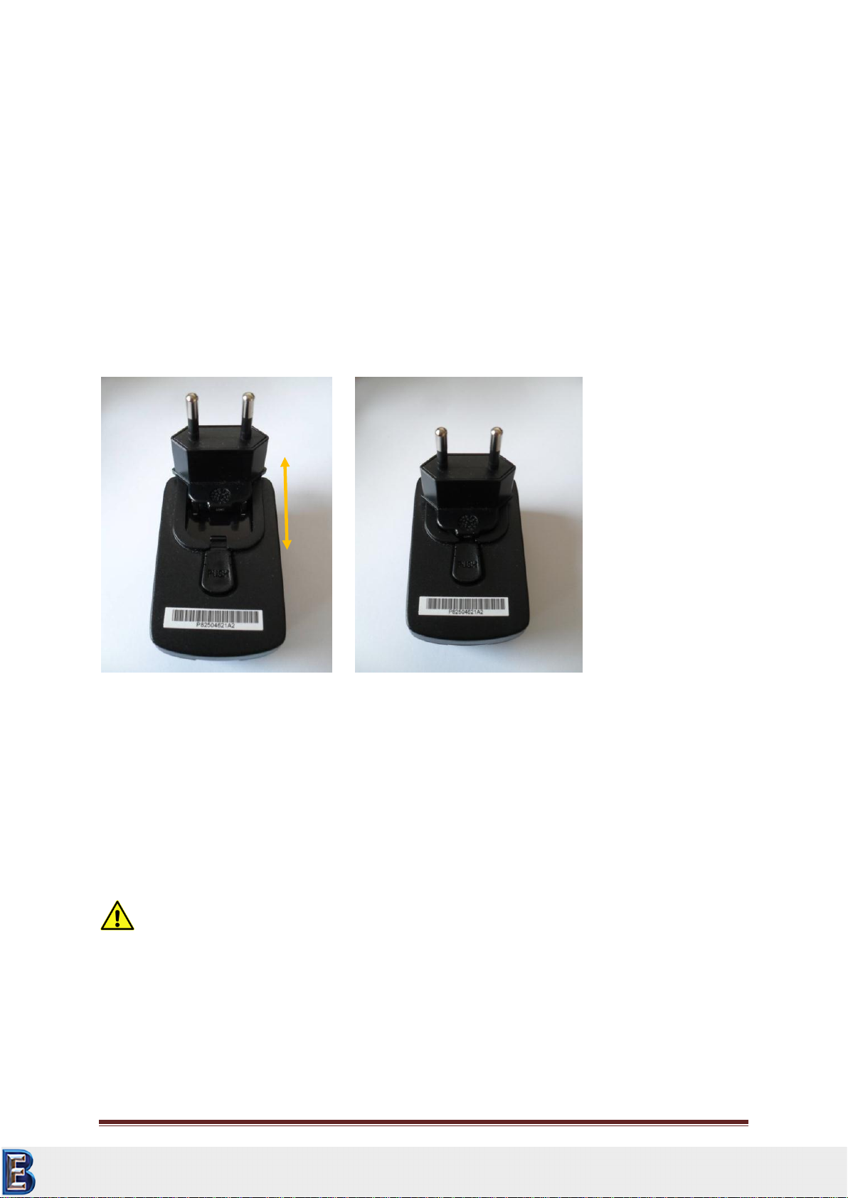
4.1 Power Supply Unit
The SONO NG power supply unit automatically adapts itself to all alternating voltages between 90
and 264 VAC (50 /60 Hz). By default, the power supply unit is equipped with alternating voltage
adapter when delivered. However, you can simply replace it with a different one. (Please also see
Section Scope of Delivery and Accessories): In order to do this, press the unlock button (1) and
disconnect the adapter. Slide in the desired adapter into the indentation until it clicks.
Figure 4.1
Figure 4.2
Depending on the state of charge, the battery will be automatically charged when connected to the
power supply unit. You can let the power supply unit plugged in without any concern, even after the
batteries are fully charged, since overloading is out of question.
4.2 Exchange Battery Pack
Attention:
Please don’t remove the battery pack or try to take this PDA apart while the SonoDur2 is charging or
the instrument is powered on. These actions will result in some damages and may invalidate your
warranty!
1
Your Complete Source for
Testing Equipment. Since 1969!
www.BergEng.com
Berg Engineering & Sales Company, Inc.
Tel 847-577-3980

NewSonic SonoDur2 Issue 04 09/2016 Page 17
The battery pack can be easily exchanged by opening the rear battery cover. Please follow the
instructions given in pictures below.
Unlock the two quick fastener and lift the cover. Pull the plastic strip on the battery and remove it.
Re-insert the battery block by latching the bottom first and then pull it down. Mount the cover (make
sure the latches of the cover fit in the mounting holes) and lock the two quick fastener.
Figure 4.6
Figure 4.7
4.3 Charging
When charging, the tester must be connected to the SONO-NG power supply unit by means of the
SONO-USB power cable. Charging of a completely discharged accumulator to 80% capacity takes up
to 2 hour and up to 4 hours to 100% capacity when using the SONO-NG.
Please note:
Do not use any other USB-cables, because the plug may fit but will not make stable electrical
connection!
Figure 4.3
Figure 4.4
Figure 4.5
Your Complete Source for
Testing Equipment. Since 1969!
www.BergEng.com
Berg Engineering & Sales Company, Inc.
Tel 847-577-3980
NewSonic SonoDur2 Issue 04 09/2016 Page 18
If the SonoDur2 is connected to a USB port of a PC/laptop, charging is only possible when the
instrument is turned off! Nevertheless charging time increases significantly because the USB port
could only supply limited power.
Please note:
During on state, the USB-port is not able to deliver enough power to charge the battery pack.
Fully discharged batteries or deep-discharged cells (due to prolonged storage) must be charged by
means of the SONO-NG. A connection to a USB port would result in a shutdown of the USB port due
to the high charging current level!
Prior to initial operation, the SonoDur2 hardness tester should be connected at least 4 hours to the
SONO-NG battery charger.
Attention:
Please also observe our safety guidelines under “Section Safety Information“, page 12.
In order to ensure a long life of the block battery, please follow the instructions below:
After the device has been used for the first time, we recommend to fully charge/discharge
the battery between 2 and 3 times.
Please use the device only within the specified temperature range (see section “Technical
Data –SonoDur2“, page 65)!
The battery life is greatly reduced at higher ambient temperatures. Optimum charging takes
place at temperatures between 0°C and 25°C. We therefore recommend unplugging the
power supply unit at higher temperatures.
Please prevent the batteries from becoming completely discharged. You may even charge
the device more frequently, since it does not harm the capacity of the battery!
Avoid storage at high temperatures, for instance, don’t leave the device in your car during
summer!
If you keep the device out of service for a prolonged time, charge the battery pack and store
the device in a dry and cool place.
Please note:
Remove the USB cable SONO USB from the device, if voltage is not supplied to the power supply unit
or USB port. The SonoDur2 could become discharged!
Your Complete Source for
Testing Equipment. Since 1969!
www.BergEng.com
Berg Engineering & Sales Company, Inc.
Tel 847-577-3980

NewSonic SonoDur2 Issue 04 09/2016 Page 19
4.4 Operating Time
The operating time decisively depends on the selected mode, ambient temperature, maintenance
condition and battery’s age. Therefore, only a typical operating time can be specified, which however
cannot be guaranteed for the stated reasons.
Operation time for SonoDur2 is >8 hours under normal operating conditions and up to 6 hours
continuous operating time.
Once the error message "Main Battery Low" appears or the battery indicator flashes red, the current
series of measurements should be completed and the SonoDur2 must be connected with the SONO-
NG plug-in power supply for charging or the battery pack must be exchanged.
4.4.1 Querying of Battery Capacity
The battery status can be queried at any time by touching the status bar and then touching the
battery symbol. By acknowledging the OK button or by pressing the upper left button, you will be
returned to the program.
Figure 4.8
Figure 4.9
Your Complete Source for
Testing Equipment. Since 1969!
www.BergEng.com
Berg Engineering & Sales Company, Inc.
Tel 847-577-3980

NewSonic SonoDur2 Issue 04 09/2016 Page 20
5Turning On and Off
The device is turned on/off via the power button (bottom left most position of the keypad, see
Figure 5.1). To turn on the device, press and hold the key (3-4 sec) until you will feel a slight vibration
and the display shows the boot logo, release the key. After approx. 20 sec. the boot sequence is
finished and the start screen is shown, see Figure 5.2.
To start the SonoDur program, please press the function key F1 or touch the SonoDur icon on the
touch screen, refer to chapter Turning On and Off, page 20.
After the instrument has powered on, pressing the power button again will pop up the shutdown
menu. Touching the red power off icon on the screen will switch off the instrument (Figure 5.4).
Close the SonoDur program before switch off to avoid data loss!
Please note:
Please connect or disconnect probes only when the instrument is switched. Otherwise the
instrument may not recognize the probe and the message “COM6: is not the virtual USB-interface….”
will be displayed (Figure 6.1). In this case the instrument should be switched off and on again.
You can also force the instrument to shut down at any time by holding the power button for
approximately 8 seconds until the instrument switches off.
Figure 5.1
Figure 5.2
Figure 5.3
Figure 5.4
Your Complete Source for
Testing Equipment. Since 1969!
www.BergEng.com
Berg Engineering & Sales Company, Inc.
Tel 847-577-3980
Table of contents
Other NewSonic Test Equipment manuals


