Newtec SAT2200 User manual

Satellite Terminal
Installation Guide
Release 2.2
Ref. nr. 37628

Table of Contents
Satellite Terminal Installation Guide
version 2.0 - 2 -
Table of Contents
Table of Contents .................................................................................................................................. 2
1Introduction..................................................................................................................................... 3
1.1 About this Guide ...................................................................................................................... 3
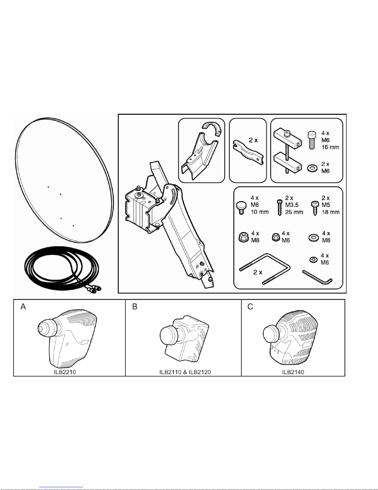
1.2 Material Provided in the Box.................................................................................................... 4
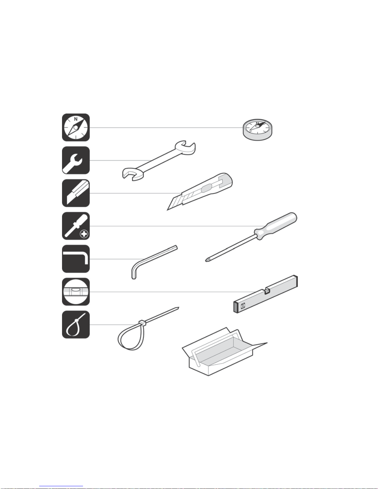
1.3 Required Installation Tools ...................................................................................................... 6
2Antenna Installation....................................................................................................................... 7
2.1 Step 1: Choosing a Suitable Location ..................................................................................... 7
2.2 Step 2: Mounting the Antenna Pole......................................................................................... 8
2.3 Step 3: Preparing the Masthead.............................................................................................. 9
2.4 Step 4: Setting the Elevation Angle....................................................................................... 10
2.5 Step 5: Mounting the Antenna............................................................................................... 12
2.6 Step 6: Mounting the iLNB..................................................................................................... 15
2.7 Step 7: Connecting the Equipment........................................................................................ 19
3Terminal Installation..................................................................................................................... 25
3.1 Step 1: Select Outdoor Unit................................................................................................... 26
3.2 Step 2: Select Spot Beam...................................................................................................... 27
3.3 Step 3: Pointing your Antenna............................................................................................... 28
3.4 Step 4: Software Download ................................................................................................... 39
3.5 Step 5: Validation of the Installation ...................................................................................... 40
3.6 Finish Installation................................................................................................................... 45
4Annex: Restart Installation.......................................................................................................... 47

Introduction Satellite Terminal Installation Guide
version 2.0 - 3 -
1 Introduction
1.1 About this Guide
This guide provides a step-by-step procedure to install your satellite terminal.
Before installing
Before starting to install your satellite terminal, it is important to
read the safety precautions.
These are available on the CD included in the box.
Follow the entire procedure
When installing the antenna, it is important that you follow the entire procedure step-by-step.
Skipping one or more sections might lead to incomplete or incorrect installation and/or operation of
your satellite terminal.
Related documentation
•The antenna pointing information, which contains the geographical pointing data. This
information is provided by your Service Provider, either as a booklet included in the box,
either in a different format.
•The Safety Precautions (available on the CD included in the box);
•The MDM2200 User Manual, describing the features and the web interface of the modem
(available on the CD included in the box);
•The Terminal Specifications (available on the CD included in the box);
•The Troubleshooting Guide, describing some possible error scenarios you might encounter
during the installation of your satellite terminal, and their respective solutions
(available on the CD included in the box).
Copyright © 2014 Newtec Cy N.V.

Introduction Satellite Terminal Installation Guide
version 2.0 - 4 -
1.2 Material Provided in the Box

Introduction Satellite Terminal Installation Guide
version 2.0 - 5 -

Introduction Satellite Terminal Installation Guide
version 2.0 - 6 -
1.3 Required Installation Tools

Antenna Installation Satellite Terminal Installation Guide
version 2.0 - 7 -
2 Antenna Installation
2.1 Step 1: Choosing a Suitable Location
Outdoors: Antenna & iLNB
•When setting up the antenna base, take into account the orientation of the antenna.
Orientation data is provided by your Service Provider.
•The antenna must have a clear view towards the satellite
(without any buildings, trees,... that may hinder the signal).
•To connect the iLNB to the Modem, use a coax cable. You can use the provided coax cable,
or a coax cable with the same specifications as described in the Terminal Specifications
available on the CD. The coax cable included in the box is 30 meters long.
Indoors: Modem and computer
Put the Modem indoors in a dry room and connect to:
•The antenna (with the coax cable);
•Your computer (with a network cable). Use the network cable provided in the box or a cable
of your choice (for example if you need a longer cable to connect the modem to your
computer);
•A wall outlet (with the power adapter provided in the box).
Power adapter specifications: universal input range 100-240 Volt, 50-60Hz.
These steps are described further in this document.

Antenna Installation Satellite Terminal Installation Guide
version 2.0 - 8 -
2.2 Step 2: Mounting the Antenna Pole
Material you have to provide yourself
•A solid base for the antenna, made of concrete or firmly attached to a wall;
•An antenna pole.
Antenna pole requirements
•The antenna pole must be installed on a solid base and made of galvanized steel;
•Minimum diameter: 45mm (60mm recommended);
•Maximum diameter: 70mm.
When fixing the antenna pole to the base, use a spirit level to make sure the antenna pole stands in a
vertical upright position.

Antenna Installation Satellite Terminal Installation Guide
version 2.0 - 9 -
2.3 Step 3: Preparing the Masthead
Unfold the feed arm and fix its position by tightening the two pre-mounted screws on the masthead.

Antenna Installation Satellite Terminal Installation Guide
version 2.0 - 10 -
2.4 Step 4: Setting the Elevation Angle
1 Mount the elevation adjustment bolt onto the masthead. Do not yet tighten the four elevation
bolts, as the elevation angle should be set first.

Antenna InstallationSatellite Terminal Installation Guide
version 2.0 - 11 -
2 Use the antenna pointing information provided by your Service Provider to look up the
elevation angle that applies to your location, or to the city closest to your location.
Using the elevation scale on the left side of the masthead, set the elevation angle to the value
you have found in the antenna pointing information, by rotating the elevation adjustment bolt
with the hex key.
3 When the elevation angle is set, tighten the four elevation bolts to fix the elevation angle.

Antenna Installation Satellite Terminal Installation Guide
version 2.0 - 12 -
2.5 Step 5: Mounting the Antenna
1 Use the antenna pointing information provided by your Service Provider to look up the
azimuth angle that applies to your location, or to the city closest to your location.
Mount the masthead to the antenna pole, ensuring that the unfolded feed arm points to the
azimuth value you have found in the antenna pointing information. Use a compass to verify.

Antenna Installation Satellite Terminal Installation Guide
version 2.0 - 13 -
2 Secondly, mount the antenna dish onto the masthead.

Antenna Installation Satellite Terminal Installation Guide
version 2.0 - 14 -
3 Thirdly, mount the iLNB clamp onto the feed arm.

Antenna Installation Satellite Terminal Installation Guide
version 2.0 - 15 -
2.6 Step 6: Mounting the iLNB
2.6.1 Ka-band iLNB
If you have a Ka-band iLNB (ILB2210), mount it into the clamp. Ensure that the clasp at the bottom of
the iLNB fits into the notch of the clamp. The two screws can be tightened.
When finished, please proceed to Step 7.

Antenna Installation Satellite Terminal Installation Guide
version 2.0 - 16 -
2.6.2 Ku-band iLNB
1 If you have a Ku-band iLNB (ILB2110, ILB2120, ILB2140), mount it into the clamp. Do not yet
tighten the two screws, as the polarization angle should be set first.

Antenna Installation Satellite Terminal Installation Guide
version 2.0 - 17 -
2 Use the antenna pointing information provided by your Service Provider to look up the
polarization angle that applies to your location, or to the city closest to your location.
Identify the angle marker on the iLNB feedclamp as indicated in the figure below. The angle
marker is in fact the line that separates the top and bottom part of the feedclamp.
Using the polarization scale on the iLNB, set the polarization angle to the value you have
found in the antenna pointing information. Examples for three values are shown in the figure
below.

Antenna Installation Satellite Terminal Installation Guide
version 2.0 - 18 -
3 When the polarization angle is set, tighten the two screws to fix the polarization angle.

Antenna Installation Satellite Terminal Installation Guide
version 2.0 - 19 -
2.7 Step 7: Connecting the Equipment
2.7.1 Preparing the Coax Cable
The twin coax cable is delivered with two premounted waterproof connectors on one side. This is the
outdoor end of the cable. The other side of the cable has no connectors attached yet, which allows
the length of the cable to be reduced (e.g. if required for practical reasons). This is the indoor end of
the cable.
Execute the following steps to attach the F-connectors to the indoor end of the cable.
You will need a cutter (and possibly pliers) to connect the F-connectors.
1 Strip the coax cable as shown below. Do not remove the aluminum foil or fold it back.

Antenna Installation Satellite Terminal Installation Guide
version 2.0 - 20 -
2 Fold the wire shielding backwards over the cable jacket.
3 Cut away the plastic shield. Screw the F-connector to the wire by hand.
4 The result should resemble like the figure below:
Repeat this procedure for the second F-connector.
Table of contents
Other Newtec Marine GPS System manuals