Waters 2475 Manual

2475 Multi λ
Fluorescence Detector
Operator’s Guide
71500247502/Revision F
Copyright © Waters Corporation 2010
All rights reserved

ii
Copyright notice
© 2010 WATERS CORPORATION. PRINTED IN THE UNITED STATES OF
AMERICA AND IN IRELAND. ALL RIGHTS RESERVED. THIS
DOCUMENT OR PARTS THEREOF MAY NOT BE REPRODUCED IN ANY
FORM WITHOUT THE WRITTEN PERMISSION OF THE PUBLISHER.
The information in this document is subject to change without notice and
should not be construed as a commitment by Waters Corporation. Waters
Corporation assumes no responsibility for any errors that may appear in this
document. This document is believed to be complete and accurate at the time
of publication. In no event shall Waters Corporation be liable for incidental or
consequential damages in connection with, or arising from, its use.
Trademarks
Alliance, Millennium, and Waters are registered trademarks, and Empower,
LAC/E, SAT/IN, and “THE SCIENCE OF WHAT’S POSSIBLE.” are
trademarks of Waters Corporation.
Teflon is a registered trademark of E. I. du Pont de Nemours and Company.
Windows and Windows NT are registered trademarks of Microsoft
Corporation.
Other registered trademarks or trademarks are the sole property of their
owners.

iii
Customer comments
Waters’ Technical Communications department invites you to tell us of any
errors you encounter in this document or to suggest ideas for otherwise
improving it. Please help us better understand what you expect from our
documentation so that we can continuously improve its accuracy and
usability.
We seriously consider every customer comment we receive. You can reach us
Contacting Waters
Contact Waters®with enhancement requests or technical questions regarding
the use, transportation, removal, or disposal of any Waters product. You can
reach us via the Internet, telephone, or conventional mail.
Safety considerations
Some reagents and samples used with Waters instruments and devices can
pose chemical, biological, and radiological hazards. You must know the
potentially hazardous effects of all substances you work with. Always follow
Waters contact information
Contacting medium Information
Internet The Waters Web site includes contact
information for Waters locations worldwide.
Visit www.waters.com.
Telephone and fax From the USA or Canada, phone 800
252-HPLC, or fax 508 872 1990.
For other locations worldwide, phone and fax
numbers appear in the Waters Web site.
Conventional mail Waters Corporation
34 Maple Street
Milford, MA 01757
USA

iv
Good Laboratory Practice, and consult your organization’s safety
representative for guidance.
Safety advisories
Consult Appendix A for a comprehensive list of warning and caution
advisories.
Operating this instrument
When operating this instrument, follow standard quality-control (QC)
procedures and the guidelines presented in this section.
Applicable symbols
Audience and purpose
This guide is intended for personnel who install, operate, and maintain the
2475 Multi λFluorescence detector.
Symbol Definition
Manufacturer
Authorized representative of the European
Community
Confirms that a manufactured product complies
with all applicable European Community
directives
Australia C-Tick EMC Compliant
Confirms that a manufactured product complies
with all applicable United States and Canadian
safety requirements
Consult instructions for use

v
Intended use of the instrument
Waters designed the 2475 Multi λFluorescence Detector to analyze samples
in high-performance liquid chromatography (HPLC) applications. The 2475
Multi λFluorescence detector is for research use only
Calibrating
To calibrate LC systems, follow acceptable calibration methods using at least
five standards to generate a standard curve. The concentration range for
standards should include the entire range of QC samples, typical specimens,
and atypical specimens.
When calibrating mass spectrometers, consult the calibration section of the
operator’s guide for the instrument you are calibrating. In cases where an
overview and maintenance guide, not operator’s guide, accompanies the
instrument, consult the instrument’s online Help system for calibration
instructions.
Quality-control
Routinely run three QC samples that represent subnormal, normal, and
above-normal levels of a compound. Ensure that QC sample results fall within
an acceptable range, and evaluate precision from day to day and run to run.
Data collected when QC samples are out of range might not be valid. Do not
report these data until you are certain that the instrument performs
satisfactorily.
ISM classification
ISM Classification: ISM Group 1 Class B
This classification has been assigned in accordance with CISPR 11 Industrial
Scientific and Medical (ISM) instruments requirements. Group 1 products
apply to intentionally generated and/or used conductively coupled
radio-frequency energy that is necessary for the internal functioning of the
equipment. Class B products are suitable for use in both commercial and
residential locations and can be directly connected to a low voltage,
power-supply network.

vi
EC authorized representative
Waters Corporation (Micromass UK Ltd.)
Floats Road
Wythenshawe
Manchester M23 9LZ
United Kingdom
Telephone: +44-161-946-2400
Fax: +44-161-946-2480
Contact: Quality manager

Table of Contents vii
Copyright notice ................................................................................................... ii
Trademarks ............................................................................................................ ii
Customer comments ............................................................................................ iii
Contacting Waters ............................................................................................... iii
Safety considerations .......................................................................................... iii
Safety advisories................................................................................................. iv
Operating this instrument ................................................................................. iv
Applicable symbols ............................................................................................. iv
Audience and purpose......................................................................................... iv
Intended use of the instrument........................................................................... v
Calibrating ........................................................................................................... v
Quality-control ..................................................................................................... v
ISM classification .................................................................................................. v
ISM Classification: ISM Group 1 Class B .......................................................... v
EC authorized representative ........................................................................... vi
1 Theory of Operation .............................................................................. 1-1
Fluorescence theory ......................................................................................... 1-2
Fluorescence detection .................................................................................... 1-3
Overview........................................................................................................... 1-3
Excitation sources............................................................................................ 1-3
Types of light sources ...................................................................................... 1-3
Excitation wavelength selection ..................................................................... 1-3
Exciting the sample ......................................................................................... 1-4
Flow cell............................................................................................................ 1-4
Measuring fluorescence .................................................................................. 1-4
Quantitation..................................................................................................... 1-4
Emission wavelength selection ....................................................................... 1-4
Table of Contents

viii Table of Contents
Photomultiplier tube........................................................................................ 1-4
Scanning........................................................................................................... 1-5
Multichannel operation ................................................................................... 1-5
Fluorescence data ............................................................................................ 1-5
References ........................................................................................................ 1-6
Detector description ........................................................................................ 1-7
Features............................................................................................................ 1-7
Principles of operation .................................................................................... 1-9
Detector optics.................................................................................................. 1-9
Optics assembly light path............................................................................ 1-10
Photomultiplier (PMT) calibration ............................................................... 1-12
PMT sensitivity.............................................................................................. 1-12
Filtering noise ................................................................................................ 1-12
Electronics...................................................................................................... 1-13
Wavelength verification and test.................................................................. 1-14
Operational modes .......................................................................................... 1-14
Single-channel mode...................................................................................... 1-14
Multichannel mode ........................................................................................ 1-15
Spectrum scanning ......................................................................................... 1-16
Lamp energy and performance ................................................................... 1-16
Auto-optimize gain ......................................................................................... 1-17
Method optimization...................................................................................... 1-18
Example of recommended method development approach.......................... 1-19
Ensuring gain optimization for each peak of interest ................................. 1-20
Startup diagnostic tests ................................................................................ 1-21
Mobile-phase solvent degassing .................................................................. 1-21
Wavelength selection ..................................................................................... 1-22
2 Setting Up the Detector ........................................................................ 2-1
Before you begin ............................................................................................... 2-2
Installing the detector ..................................................................................... 2-3

Table of Contents ix
Plumbing the detector ..................................................................................... 2-3
Connecting columns......................................................................................... 2-3
Assembling fittings .......................................................................................... 2-4
Making tubing connections ............................................................................. 2-5
Making signal connections ............................................................................. 2-5
Component connection overview..................................................................... 2-6
Connecting the Ethernet cable........................................................................ 2-7
Choosing signal connections.......................................................................... 2-10
Making I/O signal connections...................................................................... 2-11
Signal connections ......................................................................................... 2-12
Connecting an Alliance separations module ................................................ 2-14
Connecting RS-232 devices ........................................................................... 2-18
Connecting Ethernet devices......................................................................... 2-20
Connecting other devices .............................................................................. 2-23
Required materials ........................................................................................ 2-23
Connecting cables .......................................................................................... 2-23
Connecting a data system using a Bus SAT/IN module.............................. 2-24
Connecting a 746 data module...................................................................... 2-27
Connecting a chart recorder.......................................................................... 2-28
Connecting a 600-series pump ...................................................................... 2-29
Connecting a 717plus Autosampler .............................................................. 2-33
Connecting to the electricity source .......................................................... 2-36
3 Using the Detector ................................................................................. 3-1
Starting the detector ........................................................................................ 3-2
Initializing the detector................................................................................... 3-2
Startup failure ................................................................................................. 3-3
Idle mode .......................................................................................................... 3-4
Using the operator interface .......................................................................... 3-4
Using the display ............................................................................................. 3-4
Fluorescence and message icons ..................................................................... 3-5
Using the keypad ............................................................................................. 3-9
Navigating the user interface ....................................................................... 3-16
Navigating to and from the home screen...................................................... 3-16

x Table of Contents
Preparing to start a run ................................................................................ 3-18
Setting up a run ............................................................................................. 3-18
Accessing primary and secondary functions ................................................ 3-19
Operating the trace and scale functions....................................................... 3-23
Configuring the detector................................................................................ 3-25
Configuring event inputs and contact closures............................................ 3-25
Setting pulse periods ..................................................................................... 3-26
Setting the Display Contrast ........................................................................ 3-27
Displaying system information ..................................................................... 3-28
Using Online Help ......................................................................................... 3-28
Operating the detector .................................................................................. 3-28
Two operating modes..................................................................................... 3-29
Standalone operation..................................................................................... 3-29
Remote control operation for 474 emulation mode via RS-232 ................... 3-29
Remote control operation via Ethernet connection using 2475 instrument
control software........................................................................................ 3-34
Verifying the detector .................................................................................... 3-34
Manual wavelength calibration .................................................................... 3-35
Normalizing emission units .......................................................................... 3-36
Operating the detector in single-channel mode ........................................... 3-37
Operating the detector in multichannel mode ............................................. 3-38
Setting gain and EUFS.................................................................................. 3-40
Programming methods and events ............................................................. 3-43
Storing methods............................................................................................. 3-43
Programming timed events ........................................................................... 3-44
Programming threshold events..................................................................... 3-47
Storing a method............................................................................................ 3-49
Retrieving a method ...................................................................................... 3-50
Viewing events within a method................................................................... 3-50
Resetting a method ........................................................................................ 3-51
Clearing events .............................................................................................. 3-51
Scanning spectra ............................................................................................. 3-52
Types of scanning........................................................................................... 3-52
Before you begin............................................................................................. 3-52
Scanning new spectra.................................................................................... 3-57

Table of Contents xi
Parameters used for sample and zero-scans ................................................ 3-58
Programming a zero-scan.............................................................................. 3-59
Running a sample scan.................................................................................. 3-60
Scanning using a static flow cell................................................................... 3-64
Managing results ............................................................................................. 3-65
Storing a spectrum......................................................................................... 3-65
Getting information about a stored spectrum.............................................. 3-66
Reviewing a stored spectrum ........................................................................ 3-66
Creating a difference spectrum (subtracting a spectrum)........................... 3-67
Replaying a spectrum .................................................................................... 3-67
Conserving lamp life ...................................................................................... 3-67
Manually extinguishing the lamp................................................................. 3-68
Manually lighting the lamp........................................................................... 3-69
Using a timed event method to program the lamp ...................................... 3-70
Shutting down the detector .......................................................................... 3-70
4 Maintenance Procedures ..................................................................... 4-1
Contacting Waters technical service ............................................................ 4-2
Maintenance considerations .......................................................................... 4-2
Safety and handling......................................................................................... 4-2
Spare parts....................................................................................................... 4-3
Routine maintenance ....................................................................................... 4-3
Removing the front-left-hand panel cover...................................................... 4-4
Inspecting, cleaning, and replacing the flow cell ..................................... 4-5
Flushing and passivating the flow cell ........................................................... 4-5
Removing the flow cell assembly .................................................................... 4-6
Replacing the flow cell..................................................................................... 4-7
Replacing the lamp ........................................................................................... 4-8
When to replace the lamp................................................................................ 4-8
Removing the lamp .......................................................................................... 4-9
Installing the new lamp................................................................................. 4-12
Recording the new lamp’s serial number ..................................................... 4-13

xii Table of Contents
Replacing the fuses ......................................................................................... 4-14
Cleaning the instruments exterior ............................................................. 4-15
5 Error Messages, Diagnostic Tests, and Troubleshooting ............. 5-1
Startup error messages ................................................................................... 5-2
Operational error messages ........................................................................... 5-3
User-selected diagnostic tests and settings ................................................ 5-8
Overview of diagnostic tests and settings ...................................................... 5-8
Sample and reference energy diagnostic tests ............................................. 5-11
Raman signal-to-noise test diagnostic test................................................... 5-12
Input and output diagnostic tests and settings ........................................... 5-12
Change-lamp function ................................................................................... 5-15
Testing the keypad ........................................................................................ 5-16
Testing the display ........................................................................................ 5-17
Other diagnostic tests and settings .............................................................. 5-17
Generating test peaks.................................................................................... 5-17
Overriding the optical filter setting.............................................................. 5-18
Reducing PMT sensitivity ............................................................................. 5-19
Troubleshooting .............................................................................................. 5-20
Introduction.................................................................................................... 5-20
Information needed when you contact Waters............................................. 5-20
Diagnostic tests.............................................................................................. 5-21
Power surges .................................................................................................. 5-21
Hardware troubleshooting ............................................................................ 5-21
A Safety Advisories .................................................................................. A-1
Warning symbols ............................................................................................... A-2
Task-specific hazard warnings........................................................................ A-2
Specific warnings ............................................................................................. A-3
Caution symbol .................................................................................................. A-5
Warnings that apply to all Waters instruments ......................................... A-6
Electrical and handling symbols ................................................................. A-12

Table of Contents xiii
Electrical symbols .......................................................................................... A-12
Handling symbols .......................................................................................... A-13
B Specifications ........................................................................................ B-1
C Solvent Considerations ....................................................................... C-1
Introduction ...................................................................................................... C-2
Clean solvents .................................................................................................. C-2
Solvent quality ................................................................................................. C-2
Preparation checklist....................................................................................... C-2
Water ................................................................................................................ C-2
Buffers .............................................................................................................. C-3
Tetrahydrofuran (THF) ................................................................................... C-3
Solvent miscibility ........................................................................................... C-3
How to use miscibility numbers...................................................................... C-5
Buffered solvents ............................................................................................. C-6
Head height ....................................................................................................... C-6
Solvent viscosity ............................................................................................... C-6
Mobile phase solvent degassing ................................................................... C-7
Gas solubility ................................................................................................... C-7
Solvent degassing methods ............................................................................. C-8
Solvent degassing considerations ................................................................... C-9
Wavelength selection ...................................................................................... C-9
UV cutoffs for common solvents.................................................................... C-10
Index ..................................................................................................... Index-1

xiv Table of Contents

1-1
1Theory of Operation
This chapter explains the theory and technology supporting the
operation of the Waters®2475 Multi λFluorescence Detector and
describes the instrument’s features.
Contents:
Topic Page
Fluorescence theory 1-2
Fluorescence detection 1-3
Measuring fluorescence 1-4
Detector description 1-7
Principles of operation 1-9
Operational modes 1-14
Spectrum scanning 1-16
Lamp energy and performance 1-16
Auto-optimize gain 1-17
Startup diagnostic tests 1-21
Mobile-phase solvent degassing 1-21
Wavelength selection 1-22

1-2 Theory of Operation
Fluorescence theory
Fluorescence occurs when certain molecules absorb light at specific
wavelengths, promoting the molecules to a higher energy state. As they return
to their normal energy states, the “excited” molecules release their absorbed
energy as photons.
Many organic compounds absorb light, but few fluoresce. HPLC systems that
incorporate fluorescence detection effectively identify polyaromatic
hydrocarbons, aflatoxins, vitamins, amino acids, and so on. Chemical
derivatization methods extend fluorescence detection to some nonfluorescing
compounds such as carbamate pesticides.
Fluorescence detection requires both the excitation/emission wavelengths,
leading to a higher degree of sensitivity. As a result, this technique is useful
for analyses requiring low detection limits.
Certain conditions can interfere with a compound’s ability to fluoresce,
diminishing analytical performance:
• pH changes – The loss or gain of protons and their accompanying
increase or decrease of charge affects an analyte’s electronic structure
and can enhance or degrade fluorescence.
• Temperature changes – Fluorescence decreases as the sample
temperature increases.
• Changes in the amount of dissolved oxygen – For some molecules,
fluorescence is quenched (decreased) by the presence of dissolved
oxygen.
Fluorescence detectors can be adapted to measure chemiluminescence, where
a molecule without exposure to any excitation energy emits a low intensity
signal. This type of detection can be accommodated by disabling the light
source or (as in the case of the 2475 detector) enabling a shutter to stop any
excitation light from reaching the flow cell.
The process of fluorescence detection involves an excitation source and the
following processes:
• Filtering the source light
• Exciting the sample with filtered light
• Collecting and filtering the emitted fluorescence

Fluorescence detection 1-3
• Measuring the emitted fluorescence
• Amplifying the emitted signal
Fluorescence detection
Overview
The scanning fluorescence detector illuminates a sample with a narrow band
of high-intensity light. The detector then measures the low levels of
fluorescence emitted by the sample. The emitted light is filtered, amplified,
and converted to electrical signals that can be recorded and analyzed.
Excitation sources
The typical energy source used for fluorescence detection is a lamp that
provides an intense, stable spectrum of light in the UV and visible ranges. The
resulting fluorescence intensity is directly related to the intensity of the
excitation spectrum. Thus high-sensitivity detectors use the most intense
excitation source available.
Types of light sources
Xenon lamps are the preferred source for general-purpose fluorescence
detectors.
Excitation wavelength selection
The excitation wavelength of choice requires some source-light filtering. In
modern detectors, a monochromator is typically used for the same purpose.
A monochromator is an adjustable device that you use to select wavelengths
over a wide range of the spectrum. A grating monochromator uses a
diffraction grating that passes only a small range, or bandwidth, of
wavelengths. By moving the grating, you can select wavelengths within a
particular range of wavelengths. A grating monochromator also passes
fractions, or orders, of a selected wavelength. For example, if the
monochromator is set to pass light energy at 600 nm, it also passes energy at
the second-order wavelength of 300 nm. A long-pass filter can be used to
absorb the higher-order energy produced by a monochromator. As the
excitation is selected by a monochromator, the emission (radiated energy) can

1-4 Theory of Operation
also be selected. Detectors with excitation and emission monochromators can
scan holding one monochromator at a constant setting while varying the
setting on the other. This type of operation is necessary when you are
evaluating mixtures or analyzing chemical structures.
Exciting the sample
The broad band of high-intensity light from the lamp passes through a filter or
monochromator, which selects a narrow band of wavelengths. This narrow
band of light is then directed onto the flow cell where it excites the analytes as
they pass through. Excitation wavelengths often correspond with the
absorbance wavelength of the analyte.
Flow cell
The quartz flow cell minimizes the amount of stray light that can affect the
measurement, and it maximizes the fluorescence signal. The sample
compartment is arranged so that the fluorescence energy is collected at an
angle perpendicular to the excitation (lamp) beam. This arrangement
minimizes the effect of Rayleigh scatter on background light levels.
Measuring fluorescence
To measure fluorescence in the flow cell, the detector must balance the need
for high selectivity (to distinguish specific fluorescence wavelengths) with the
need for high sensitivity (to measure low-fluorescence intensities).
Quantitation
Fluorescence is linear at low concentrations but can exhibit nonlinearity at
high concentrations.
Emission wavelength selection
A monochromator is used to select an emission wavelength.
Photomultiplier tube
The photomultiplier tube (PMT) produces a current proportional to the flux of
photons emitted by the molecules in the flow cell.

Measuring fluorescence 1-5
Scanning
Detectors equipped with excitation and emission monochromators can easily
scan a range of excitation or emission wavelengths. Changing the wavelength
involves changing the monochromator setting. During a scan, the setting on
one monochromator is held constant while the other monochromator scans a
range of wavelengths.
Multichannel operation
Detectors equipped with excitation and emission monochromators can change
the wavelength of the excitation and emission settings. In multichannel
operation, both monochromators move rapidly between the selected
wavelength pairs to produce multiple chromatogram traces. Multiple outputs
can then derive additional information from a single separation.
Fluorescence data
Detectors report their data in units of fluorescence intensity (emission) or
energy. In addition, the 2475 detector reports intensity using normalized
units to compensate for variability between individual detectors and offset any
age-related decrease in lamp intensity. When using normalized units, changes
in gain improve the signal-to-noise ratio but do not change the peak response,
conferring a high degree of bench-to-bench reproducibility of fluorescent
signal measurements.
Emission units and normalization
The 2475 detector offers two types of output units: emission and energy.
Emission units are normalized to a standard water reference, and their
magnitude is as independent of the PMT gain as possible. You can compensate
for changes that normally influence the signal strength of fluorescence
measurements, such as lamp or optics degradations, by periodically
renormalizing to the standard water reference. Renormalizing reduces
variations in fluorescence signal strengths from one detector to another.
The following equation calculates the emission units value (EU) at any time
(t):
EUt= (PMTCountst/ Gaint) × (GainRaman / CountsRaman) × 100
where

1-6 Theory of Operation
GainRaman and CountsRaman = values from the most recent execution of
the normalize units function
PMTCountstand Gaint= values at the time of data collection
Normalizing the emission units results in a water/Raman signal strength, at
Ex350 nm/Em397 nm, of 100 emission units. The xenon spectrum output is
not uniform over the detector’s operating range, and low-UV wavelengths can
degrade faster than normalization wavelengths.
Energy units
The alternative to emission units is energy units, which are similar to those
used by traditional HPLC fluorescence detectors. They directly correlate to
the anode current of the PMT, so they are directly influenced by the gain
setting. All instrumental variables, such as lamp intensity, optics efficiency,
and gain, directly influence the fluorescence emission signal strength. As a
result, energy units are less reliable. Nonetheless, when you must calculate
energy units to conform to established protocols, use the following equation:
EU = PMTCounts × K × (ReferenceCounts0/ ReferenceCountst)
where K scales the maximum detectable fluorescence signal to 10,000 units.
References
Consult the following texts for additional information on fluorescence
detection:
N. Ichinose, G. Schwedt, F. M. Schnepel, and K. Adachi, Fluorometric
Analysis in Biomedical Chemistry, Chapter 5, Wiley-Interscience: New York,
1991.
E. S. Yeung, ed., Detectors for Liquid Chromatography, Chapter 5, Wiley: New
York,1986.
W. R. Seitz, in Treatise on Analytical Chemistry, 2nd ed., P. J. Elving, E. J.
Meehan, I. M. Kolthoff, eds., Part I, Vol. 7, Chapter 4, Wiley: New York, 1981.
J. R. Lakowicz, Principles of Fluorescence Spectroscopy, Plenum: New York,
1983.
Table of contents
Other Waters Security Sensor manuals
Waters
Waters 2998 Operating manual
Waters
Waters ACQUITY RDa Operating manual
Waters
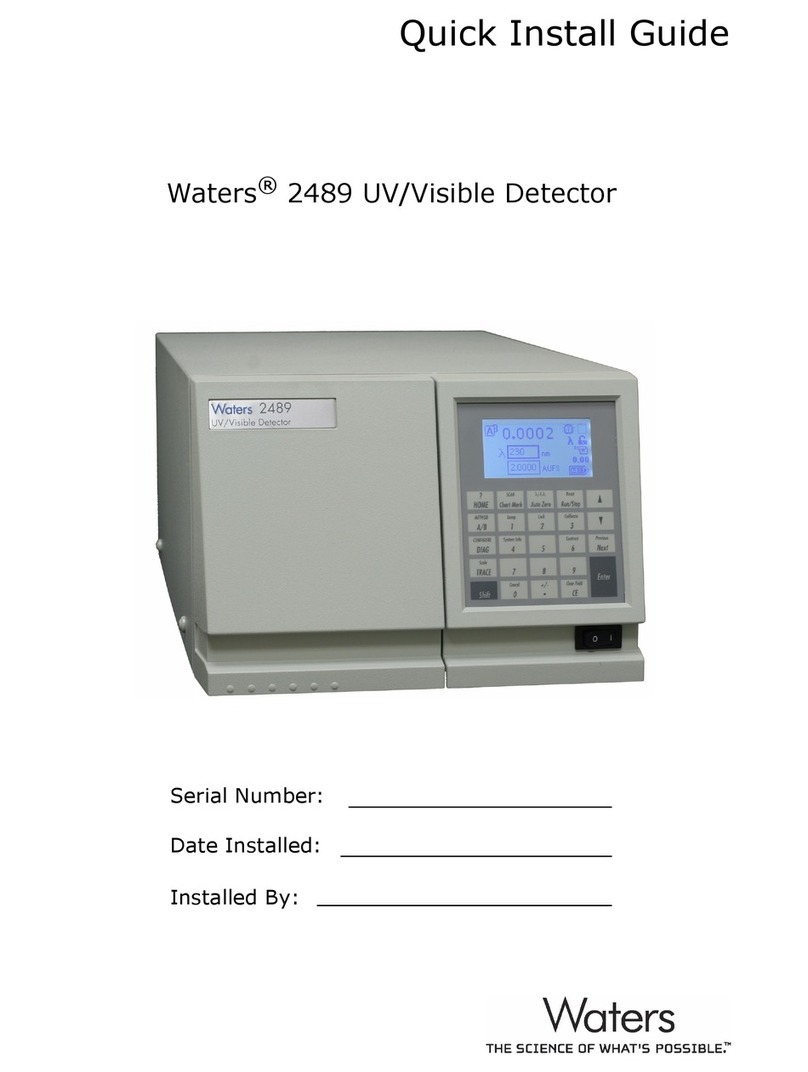
Waters 2489 User manual
Waters
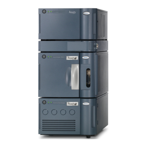
Waters ACQUITY UPLC Operating manual
Waters
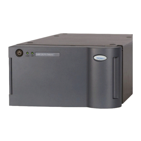
Waters 2489 Manual
Waters
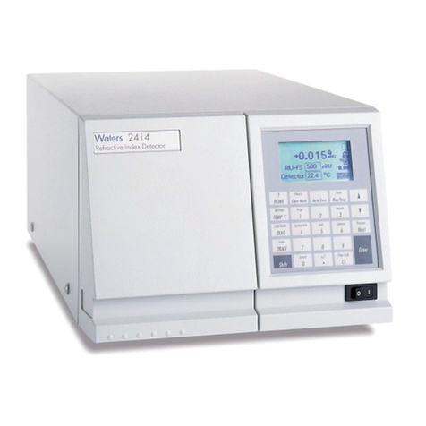
Waters 2414 Operating manual
Waters
Waters 2465 User manual
Waters
Waters ACQUITY Operating manual

Waters
Waters TQ Detector User manual
Waters
Waters 2487 User manual
Popular Security Sensor manuals by other brands

BFT
BFT SIBOX instructions

Distech Controls
Distech Controls FS-WLDS Series Hardware installation guide
DSC
DSC Force2 F2-200 Series installation instructions
System Sensor
System Sensor ED-TI Installation and maintenance instructions
dehn
dehn PHEG1 FD Seriesl Instructions for use
Integrated Power
Integrated Power HB1MSD01 instruction manual

