NEXCAM NA70010 AXIS RC-360 User manual

AXIS SHOOTING CHAIR
INSTRUCTION MANUAL
MODEL: NA70010 AXIS RC-360
THIS INSTRUCTION MANUAL MUST ALWAYS ACCOMPANY THIS PRODUCT AND BE TRANSFERRED WITH IT UPON
CHANGE OF OWNERSHIP, WHEN LOANED, OR PRESENTED TO ANOTHER PERSON.
Thank you for purchasing our NEXCAM Chair. This product is designed by hunters, for hunters. It is engineered for
safety, comfort, steady shot, and stealth, putting the odds in your favor when the moment of truth arrives.
Constructed with only the highest quality materials it’s built for years of satisfying hunts.
Read this instruction manual and all warnings in its entirety before using this product.
If you have any questions on assembly, use, safety warnings, or anything else, please contact us by email at
YOU MUST READ, UNDERSTAND, FOLLOW ALL WARNINGS AND INSTRUCTIONS BEFORE
USING THIS PRODUCT!
DO NOT EXCEED Maximum Weight Limit - 300lbs. Exceeding this limit will damage
chair and may cause personal injury.
GROUND USE ONLY! NEVER USE AT HEIGHTS ABOVE GROUND LEVEL!
USE ONLY ON LEVEL SURFACE.
ALWAYS BE SURE HEIGHT ADJUSTMENT D-PIN IS INSERTED AND LOCKED THROUGH
BUSHING AND MALE POST AND BASE IS FLAT ON SURFACE BEFORE USING CHAIR.
DO NOT tip or lean back when seated in chair so base comes off ground.
DO NOT use for any purpose other than intended use.
To avoid injuries to fingers and pinch hazards, use care when folding / adjusting shooting
rest, arm rest and adjusting spring stopper knob.
Do not modify, jump, bounce or stand on this product.
Always follow safe weapon/firearm handling practices.
Always keep firearm/crossbow pointed in a safe direction.
This product is intended for use by adults or under strict supervision of an adult.
FAILURE TO FOLLOW THESE INSTRUCTIONS CAN RESULT IN SERIOUS INJURY OR DEATH!
1
QUESTIONS? Email [email protected] for assistance.
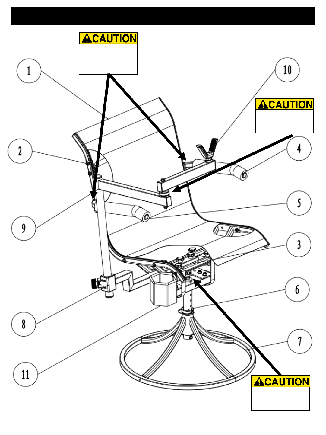
Chair Diagram
2
QUESTIONS? Email [email protected] for assistance.
Pinch Point Hazard.
Keep hands clear of
spring stopper knob
Pinch Point Hazard.
Keep hands clear of
shooting rest
Pinch Point Hazard.
Keep hands clear of
arm rest (Both
Sides)

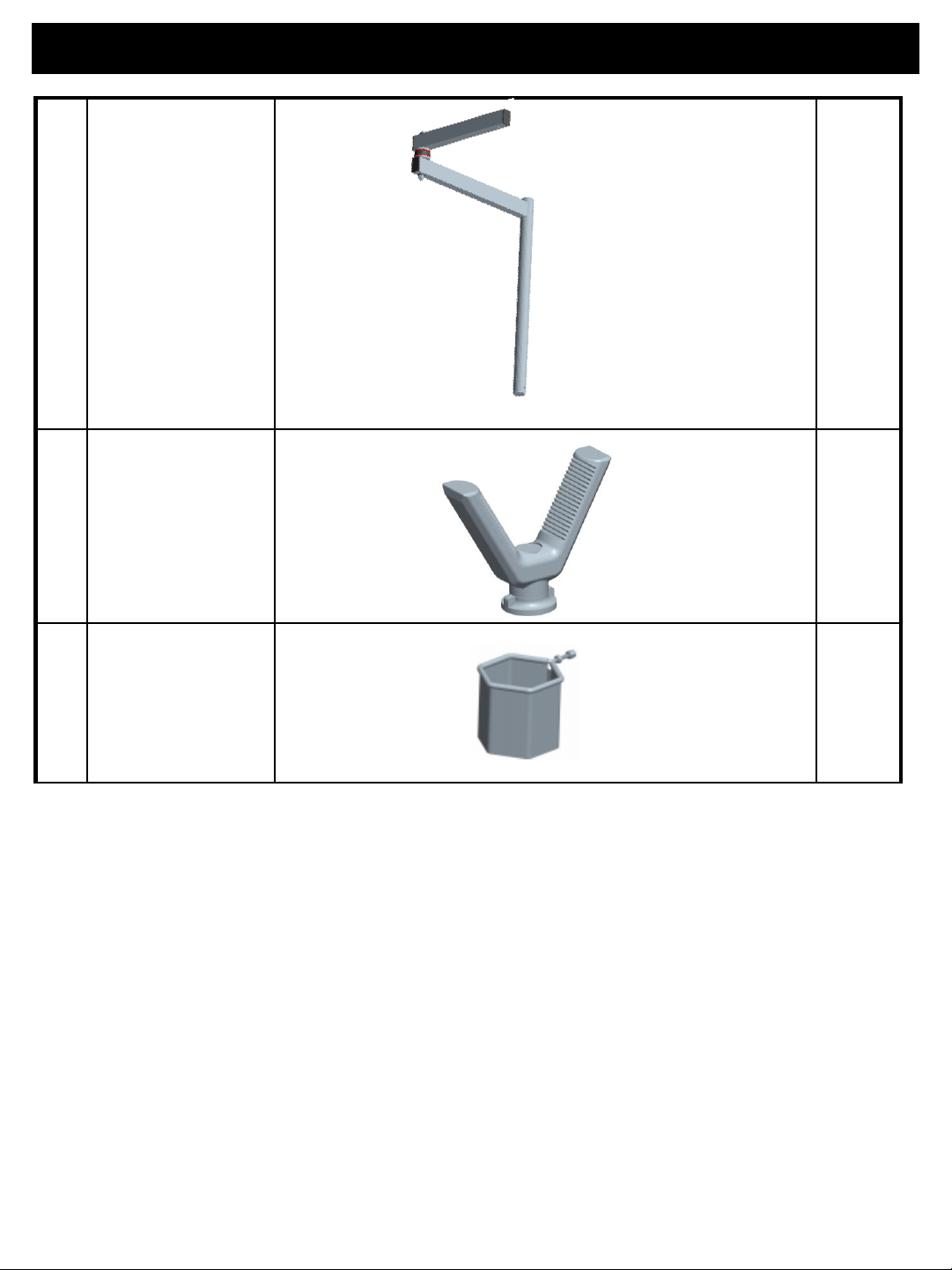
Parts List
1
Seat Fabric
Frame
Qty
1
2
Backrest
Support Frame
Qty
1
3
Seat Support
Frame
Qty
1
4
Left Side
Armrest
Qty
1
5
Right Side
Armrest
Qty
1
6
Male Post
Qty
1
7
Seat Base
Qty
1
8
Chair
Attachment
Arm
Qty
Parts List
9
Vertical Post &
Cradle Arm
Qty
1
10
Cradle
(Rubber V)
Qty
1
11
Cup Holder
Qty
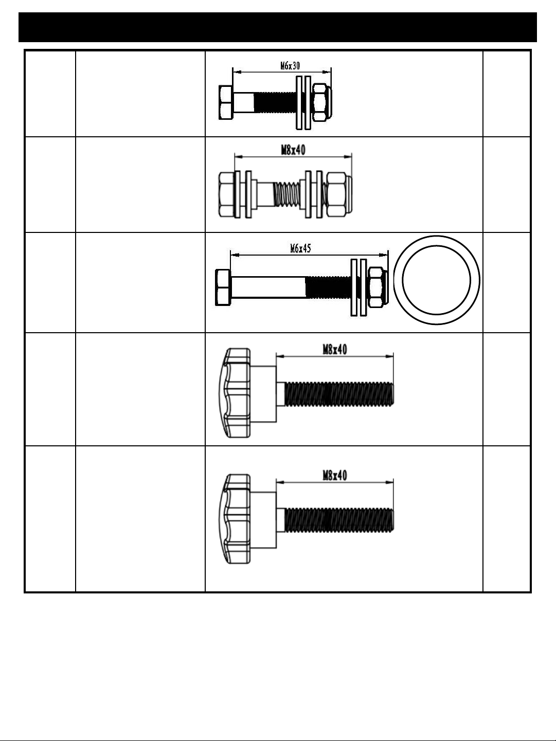
Hardware
Step
1
M6X30 (with steel
washer)
Qty
8
Step
2
M8X40 (with steel
and plastic
washer)
Qty
2
Step
4
M6X45 (with steel
washer)
White Bushing
Spacer
Qty
1
Step
5
M8X40 Knob
Qty
4
Step
6
M8X40 Knob
Qty
2
QUESTIONS? Email [email protected] for assistance. 5

Hardware
Step
7
M8x16 Knob
(With Clamp &
Coil Spring )
Qty
1
Step
8
1/4"
-20*2" (with
plastic washer)
1
M8 Wrench
(2 pcs)
(Included)
2
1/4” Wrench
(Not Included)
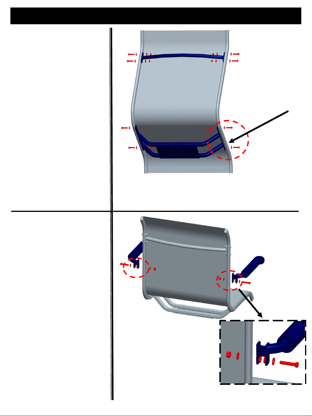
Setup Instructions
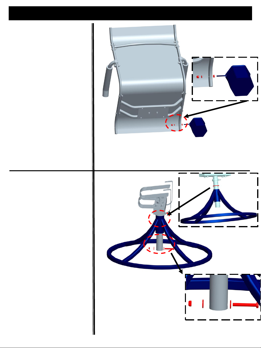
Step 1:
Install backrest support frame
(#2) and seat support frame
(#3) onto seat fabric frame
(#1) using eight (8) M6x30
Bolts, steel washers and
locknuts as shown in Figure1.
Securely tighten bolts.
IMPORTANT NOTE: Taller
side of Seat Support is
Positioned to Front of Seat.
Hint: Install one bolt on
side of backrest support
and slide other side into
place and assemble
remaining bolts. Do same
for seat support.
Step 2:
Figure 1
Install Seat & Backrest Seat Supports
7
QUESTIONS? Email [email protected] for assistance.
Taller Side of
Seat Support is
Positioned to
Front of Seat
Install left side armrest (#4) and
right side armrest (#5) on seat
fabric frame (#1) using two (2)
M8x40 bolts, steel/plastic
washers and locknuts as shown
in Figure 2.
Tighten bolts. Note do not
overtighten as these are
designed to rotate.
Figure 2
Install Left & Right Armrest
Setup Instructions
Step 3:
8
QUESTIONS? Email [email protected] for assistance.
Install cup holder (#11) onto
front side of seat using steel
washers and locknuts as
shown in Figure 3.
Figure 3
Install Cup Holder
Step 4:
Place White Bushing Spacer
onto male post (#6) and Install
male post (#6) through Seat
Base (#7) Tube.
Secure using (1) M6x45 bolt
with steel washers and locknut.
See Figure 4.
Securely tighten bolt.
Bolt prevents seat base from
coming off from seat.
Figure 4
Install Male Post into Seat Base
Place White Bushing
Spacer onto Male Post
Setup Instructions
9
QUESTIONS? Email [email protected] for assistance.
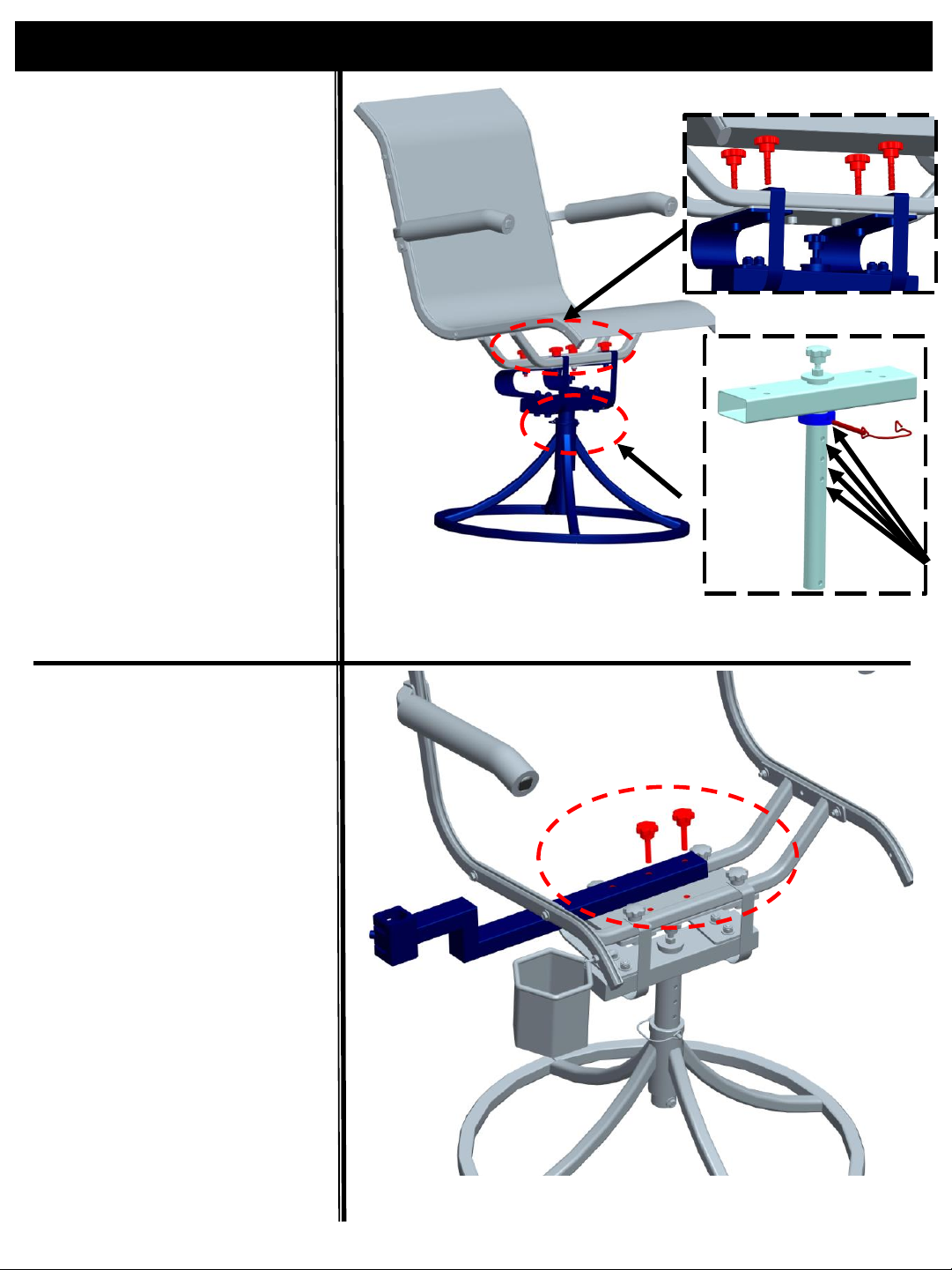
IMPORTANT NOTE:
To adjust seat height –
Position Seat Height Collar
on Male Post and Place D-
Pin through Collar and Seat
Height Hole to secure seat
Position.
Step 5:
Place seat on top of springs
on male post (#6) and
webbing stopper straps on
top of seat tubes.Assemble
seat, male post and
webbing stopper straps
using four (4) M8x40 knobs
as shown in Figure 5.
Securely tighten
Install Chair AttachmentArm
(#8) on chair seat support
base using two (2) M8x40
knobs as show in Figure 6.
Securely hand tighten both
knobs.
Step 6:
Figure 5
Install Seat
Figure 6
Install Chair Attachment Arm
To Adjust Seat Height - Position
Collar and Place D-pin through
Collar and seat height hole.
Setup Instructions
10
QUESTIONS? Email [email protected] for assistance.
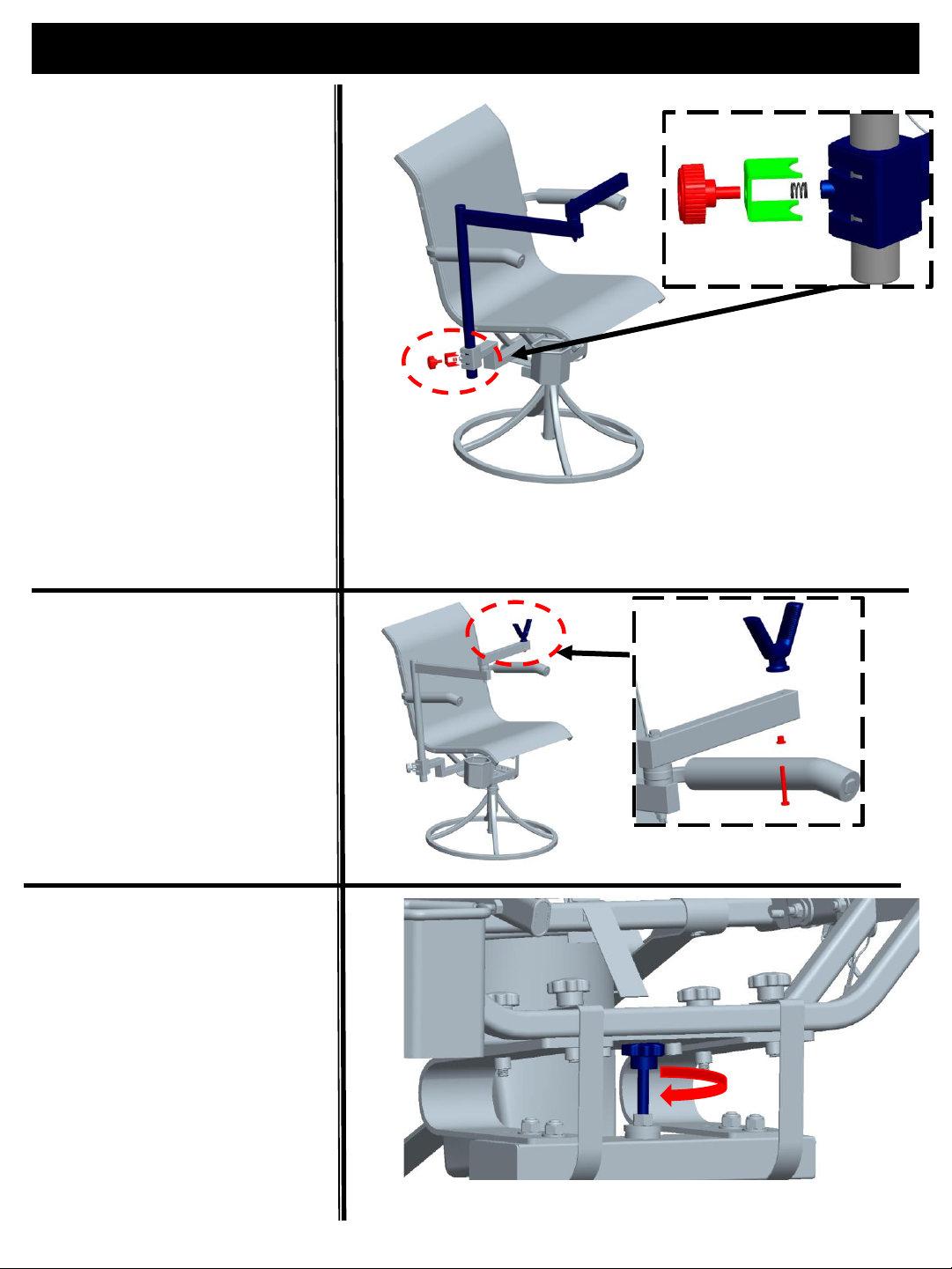
Step 9:
Adjust Spring Stopper Knob
height to adjust amount of
rocker travel as shown in
Figure 9.
This is used to steady chair
when leaning forward or
back depending on spring
position by providing a solid
stop point for rocker.
Step 8:
Step 7:
Install Vertical Post (#9)
through Chair Attachment Arm
(#8) . Using one M6x16 Knob
(With Clamp & Coil Spring )
secured on Vertical Post (#9)
by tightening the knob. Show
in Figure 7.
To adjust shooting rest height,
loosen knob and slide arm
up/down on vertical post and
retighten knob.
WARNING!Always be sure
knob are securely tightened
before use to prevent rest
from sliding down.
Install Cradle (#10) on
Cradle Arm (#9) using one (1)
1/4"-20*2" bolt, plastic
washer and locknut as
shown in Figure 8.
Figure 7
Install Install Vertical Post
Figure 9
Spring Stopper Knob
Figure 8
Install Cradle
USE:
USE ONLY ON LEVEL SURFACE. If chair is not stable or tips, do not use and
select another level surface.
ALWAYS BE SURE HEIGHT ADJUSTMENT D-PIN IS INSERTED AND LOCKED
THROUGH BUSHING AND MALE POST
DO NOT tip or lean back when seated in chair so base comes off ground.
To avoid injuries to fingers and pinch hazards, use care when folding and
adjusting shooting rest and armrests.
Before each use check to assure all locking / adjustment knobs are tight.
Never lean on or apply your weight on shooting rest. Shooting rest is
designed to only hold weight of firearm or crossbow. Applying excessive
weight could result in slippage or collapse of shooting rest.
Always hold firearm / crossbow on shooting rest. Shooting rest is
designed to aid in steadying firearm / crossbow for better shot
placement.
Always follow safe weapon/firearm handling practices. Always keep
firearm/crossbow muzzle pointed in a safe direction.
Always know your target and what lies beyond in case you miss or
projectile passes through target.
Always keep your finger off trigger until ready to fire.
When a firearm/crossbow is placed on the rest, always take care not to
bump firearm/crossbow, rest or chair.
Never use, place or store firearm/crossbow on rest if you are not sitting in
chair.
Always hold firearm/crossbow securely with both hands and keep contact
between rear of stock and shoulder at all times while aiming and firing.
Shooting Rest is not intended to hold or absorb recoil from
firearm/crossbow.
To avoid injuries to fingers and pinch hazards, only adjust spring stopper
knob when no one is seated in chair.
Prior to every use, inspect chair for damage. DO NOT USE IF ANY
DAMAGE IS VISIBLE OR SUSPECTED, including but not limited to cuts,
frayed portions, corrosion, or other damage to chair. If damage is visible
or suspected, DO NOT USE THE PRODUCT. If there are any questions, DO
NOT use the product and contact NEXCAM by email at
FAILURE TO FOLLOW THESE INSTRUCTIONS CAN RESULT IN SERIOUS
INJURY OR DEATH!
Place Chair on a level surface with base flat on surface. While next to chair, adjust seat height as shown in
setup instructions so seat height is at comfortable height.
While next to chair, adjust Spring Stopper Knob as shown in setup instructions to adjust amount of Forward
Spring Travel.
Adjusting Shooting Rest Height:
Loosen Vertical Post Knob and slide arm up/down on vertical post and retighten knob.
WARNING! Always be sure all knobs are securely tightened before use.
Chair and shooting rest are ready to be used.

MAINTENANCE AND STORAGE:
Do not modify this product in any way by making repairs, replacing parts, altering,
adding or attaching anything to it except if explicitly authorized in writing by
NEXCAM.
Use only NEXCAM authorized replacement parts. The use of unauthorized
replacement parts may result in serious injury or death.
Proper maintenance and inspection is required for this product.
This product is used to support your weight. Never use a chair that is damaged in
any way. Do not use if it is not wholly free of damage. If you have questions,
Failure to follow these instructions can lead to serious injury or death.
Should any damage occur or to purchase NEXCAM replacement parts, contact customer service by email at
support@Nexcam.com for assistance.
Care and maintenance is required to assure trouble free performance of your chair.
Store this product indoors in a clean, dry environment free from direct sunlight, harmful chemicals, excessive
heat and dust. Exposure to sunlight, excessive heat and the elements can weaken material over time.
12
QUESTIONS? Email [email protected] for assistance.

LIMITED WARRANTY*.
LIMITED ONE YEAR WARRANTY. WE WARRANT THIS PRODUCT AGAINST ANY MANUFACTURER DEFECTS
IN MATERAILS AND WORKMANSHIP FOR PERIOD OF ONE YEAR FROM DATE OF PURCHASE FROM
AUTHORIZED RETAILER TO THE ORIGINAL OWNER. WE WILL REPAIR OR REPLACE ANY PART FOUND
DEFECTIVE IF THE UNIT CLAIMED TO BE DEFECTIVE IS RETURNED TO US POSTAGE PREPAID, WITHIN
CLAIMS.
This warranty is void if any product has been subjected to misuse, abuse, neglect (including but not
limited to improper maintenance or failure to follow instructions), storage, improper use, misapplication,
accident, normal wear, modification, adjustment, or repair.
NO OTHER WARRANTIES WHETHER EXPRESSED OR IMPLIED, INCLUDING WARRANTIES OF
MERCHANTABILITY AND FITNESS FOR A PARTICULAR PURPOSE, SHALL APPLY TO THE PRODUCT.
LIMITATION OF LIABILITY
It is expressly understood that our liability for this product, whether due to breach of warranty,
negligence, strict liability, or otherwise , is limited to repair of the product as stated above. We will not
be liable for any other injury, loss, damage, or expense, whether direct or consequential, including but
not limited to loss of use, income, profit, or damage to material from use of this product howsoever
caused.
SERVICING YOUR PRODUCT:
If you need repairs or have warranty issues, contact Customer Service at support@Nexcam.com
for assistance.
PLEASE NOTE:
We reserve the right to make substitutions on warranty coverage for any reason, including but not
limited to available parts.
*Limited Warranty to the Original Owner.
NEXCAM INC.
405 Annandale Blvd.,
Annandale, MN 55302
Email: [email protected]om
Website: https://nexcam.com
13
QUESTIONS? Email [email protected] for assistance.
Table of contents
Other NEXCAM Indoor Furnishing manuals


Popular Indoor Furnishing manuals by other brands

Enclume
Enclume GI1 Assembly and installation instructions

Classic Exhibits
Classic Exhibits SEGUE DESIGNS VK-1970 Setup instructions

Direct Wicker
Direct Wicker SICILY Assembly instructions

Home Decorators
Home Decorators FTA61061 Use and care guide

Huwil
Huwil Huwilift E-Verso user manual

OVIS
OVIS 60621 manual

Rack furniture
Rack furniture CHARLESTON LOFT BED instruction manual

Desalto
Desalto Element Tavolino Assembly instruction

Alphason
Alphason JUO ALT63222 Assembly manual

Powell
Powell 21A2070 quick start guide

Furniture Values International
Furniture Values International aspenhome I248-366-1 Assembly instructions

Rousseau
Rousseau 1500 owner's manual


