1
FORM NO. L-20016-U-0305
CLUTCH
END BRAKE
END
INSTALLATION
PILOT MOUNT CLUTCH-BRAKE
1. Secure a customer supplied sheave or sprocket to the
Clutch-Brake (See Figure 2).
2. Insert the first Key (Item 30) into the shaft (See Figure 2).
3. Slide the Clutch-Brake onto shaft and key; then, insert the
second Key (Item 30) (See Figure 2).
4. TightenSetScrews(Items27and28)totherecommended
torque (See Table 1 and Figure 2).
NOTE
If a bushing for smaller diameter shafts is required, use a
bushing on both ends of the Clutch-Brake.
5. Align air inlet ports to a six o’clock down position to allow
condensation to drain out of exhaust port.
6. FastenoneoftheearsoftheClutch-Braketoafixedmember
of the machine (See Figure 2).
NOTE
The Piston Air Chamber (Item 7) floats axially
approximately 1/16 inch [1.59 mm] during operation.
Makesure securing pin allows1/16inchto 1/8 inch[1.59
mm to 3.18 mm] movement of Piston Air Chamber.
INTRODUCTION
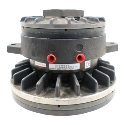
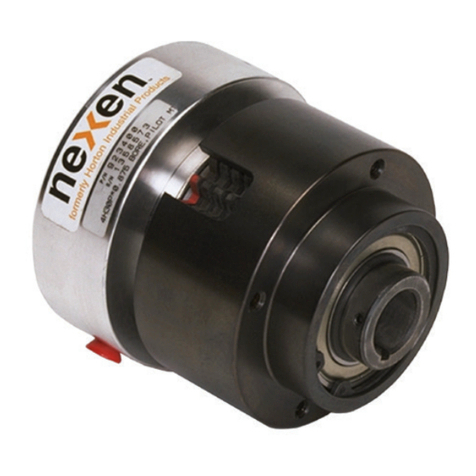
TheNexenAirChampClutch-BrakeisanAirChampClutchandan
Air Champ Brake combined into a single unit.
Becauseheatfromboththeclutchandbrakeareabsorbedwithin
theunitduringengagement,cautionmustbeusedwhenaClutch-
Brake is applied on high speed, high cyclic applications. If heat
generated from the clutching and braking of the Clutch-Brake
becomes great enough that the surface temperature of the unit
is 180oF [82.2° C] or higher, the unit may experience excessive
facingwearandareductioninbearingando-ringlife. TheClutch-
Brake must be mounted on a bearing supported, through shaft.
Twoseparateairinletsprovideindependentclutchingandbraking
action. FIGURE 1
AIR TO
CLUTCH
AIR TO
BRAKE
DESCRIPTION FWCB LWCB MWCB HWCB
35In.Lbs. 80In.Lbs. 80In.Lbs. 23Ft.Lbs.
SetScrew (Item27) [3.9N•m] [8.9N•m] [8.9N•m] [31.2N•m]
20In.Lbs. 20In.Lbs. 80In.Lbs. — —
SetScrew (Item28) [2.2N•m] [2.2N•m] [8.9N•m] — —
.
TABLE 1
RECOMMENDED TIGHTENING TORQUES
FIGURE 2
Shaft
Key
(Item 30)
Set Screw
(Item 28)
Set Screw
(Item 27)
Key
(Item 30)
Clutch-Brake
Sheave
or
Sprocket
Read this manual carefully, making full use of its explanations and instructions. The “Know How” of safe, continuous,
trouble-free operation depends on the degree of your understanding of the system and your willingness to keep all
components in proper operating condition. Pay particular attention to all NOTES, CAUTIONS, and WARNINGS to avoid the
risk of personal injury or property damage. It is important to understand that these NOTES, CAUTIONS, and WARNINGS
are not exhaustive. Nexen cannot possibly know or evaluate all conceivable methods in which service may be performed,
or the possible hazardous consequences of each method. Accordingly, anyone who uses a procedure that is not
recommendedbyNexenmustfirstsatisfythemselvesthatneithertheirsafetyorthesafetyoftheproductwillbejeopardized
by the service method selected.
WARNING
This unit has rotating parts. A guard that will not restrict the flow of cooling air around the unit must be used if the unit is
installed where injury to an operator could occur, as stated in the Occupational Safety and Health Act (OSHA), Standard
(29 CFR 1910) Section 1910.219K.
®
DIST. AUTORIZADO
MEX (55) 53 63 23 31
QRO (442) 1 95 72 60
MTY (81) 83 54 10 18
