manuals.online logo
Brands
  1. Home
  2. •
  3. Brands
  4. •
  5. Nexen
  6. •
  7. Industrial Equipment
  8. •
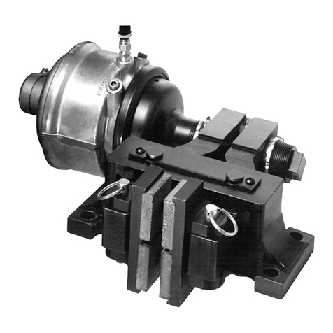
  9. Nexen Air Champ TSE-800-1 User manual

Nexen Air Champ TSE-800-1 User manual

11
11
1FORM NO. L-20286A-1199
CAUTIONCAUTION
CAUTIONCAUTION
CAUTION
This unit has rotating parts. Nexen recommends using a guard that will not restrict the flow of cooling air around the unit.This unit has rotating parts. Nexen recommends using a guard that will not restrict the flow of cooling air around the unit.
This unit has rotating parts. Nexen recommends using a guard that will not restrict the flow of cooling air around the unit.
Contact your local Nexen Distributor for information about guards designed for “Air Champ” brakes.Contact your local Nexen Distributor for information about guards designed for “Air Champ” brakes.
Contact your local Nexen Distributor for information about guards designed for “Air Champ” brakes.
CONTENTSCONTENTS
CONTENTSCONTENTS
CONTENTS
RING GUARD INSTALLATION---------------------------------------------------------------------------------------------2
PARTS REPLACEMENT-----------------------------------------------------------------------------------------------------2
REPLACEMENT PARTS-----------------------------------------------------------------------------------------------------3
PARTS LIST ------------------------------------------------------------------------------------------------------- Back Cover
NOTENOTE
NOTENOTE
NOTE
Reference L-20077 for installation, operation, and maintenance instructions.Reference L-20077 for installation, operation, and maintenance instructions.
Reference L-20077 for installation, operation, and maintenance instructions.
Readthismanualcarefully,makingfulluseofitsexplanationsandinstructions. The“KnowHow”ofsafe,continuous,
trouble-free operation depends on the degree of your understanding of the system and your willingness to keep all
componentsinproperoperatingcondition. PayparticularattentiontoallNOTES,CAUTIONS,andWARNINGStoavoid
the risk of personal injury or property damage. It is important to understand that these NOTES, CAUTIONS, and
WARNINGSarenotexhaustive. Nexencannotpossiblyknowor evaluate all conceivable methods inwhich service
may be performed, or the possible hazardous consequences of each method. Accordingly, anyone who uses a
procedure that is not recommended by Nexen must first satisfy themselves that neither their safety or the safety
of the product will be jeopardized by the service method selected.
FORM NO. L-20286A-1199
TSE-800TSE-800
TSE-800TSE-800
TSE-800 TT
TT
TOO
OO
O TSE-800-1 BRAKETSE-800-1 BRAKE
TSE-800-1 BRAKETSE-800-1 BRAKE
TSE-800-1 BRAKE
CONVERSION KIT INSTRCONVERSION KIT INSTR
CONVERSION KIT INSTRUCTIONSUCTIONS
UCTIONSUCTIONS
UCTIONS
“AirChamp ”®
®
DIST. AUTORIZADO
MEX (55) 53 63 23 31
QRO (442) 1 95 72 60
MTY (81) 83 54 10 18
[email protected]
22
22
2
FORM NO. L-20286A-1199
RING GUARD INSTALLATION
WARNINGWARNING
WARNINGWARNING
WARNING
Always have a Ring Guard Assembly in place whenAlways have a Ring Guard Assembly in place when
Always have a Ring Guard Assembly in place when
operating Nexen Clutches or Brakes. Nexenoperating Nexen Clutches or Brakes. Nexen
operating Nexen Clutches or Brakes. Nexen
recommends using Product No. 826300 with the TSE-recommends using Product No. 826300 with the TSE-
recommends using Product No. 826300 with the TSE-
800-1 Brake.800-1 Brake.
800-1 Brake.
1. Slide the Ring Guard over the TSE Brake by aligning the
Ring Guard attachment hook ends with the notches in
the TSE Housing; then, turn the Ring Guard to the closest
attachment hole.
2. Secure the Ring Guard to the Housing of the TSE Brake
using the four Pan Head Screws, Flat Washers, Lock
Washers, and Hex. Head Nuts provided with the Ring
Guard (See Figure 2).
WARNINGWARNING
WARNINGWARNING
WARNING
Shoulder Screws are spring loaded. Always wearShoulder Screws are spring loaded. Always wear
Shoulder Screws are spring loaded. Always wear
safety goggles when working with spring or tensionsafety goggles when working with spring or tension
safety goggles when working with spring or tension
loaded fasteners or devices.loaded fasteners or devices.
loaded fasteners or devices.
1. Alternately and evenly remove and discard old Shoulder
Screws (Item 6) (See Figure 1).
2. Remove and discard old Cylinder (Item 10) (See Figure 1).
3. Remove Compression Springs (Item 7) (See Figure 1).
4. Remove and discard the old O-ring Seals (Items 11 and
12) (See Figure 1).
11
11
11414
1414
14 55
55
51515
1515
15 44
44
488
88
899
99
91212
1212
12 1111
1111
11 1010
1010
10
1616
1616
16
22
22
2
33
33
3
66
66
6
PARTS REPLACEMENTPARTS REPLACEMENT
PARTS REPLACEMENT
NOTENOTE
NOTENOTE
NOTE
This conversion kit requires complete disassembly of the TSE-800. In addition to the following procedure, it isThis conversion kit requires complete disassembly of the TSE-800. In addition to the following procedure, it is
This conversion kit requires complete disassembly of the TSE-800. In addition to the following procedure, it is
recommended to replace the friction facings, compression springs, and hardware during rebuild (reference PARTSrecommended to replace the friction facings, compression springs, and hardware during rebuild (reference PARTS
recommended to replace the friction facings, compression springs, and hardware during rebuild (reference PARTS
LIST information in maintenance manual L-20077 for facing and repair kit numbers). If friction facings, compressionLIST information in maintenance manual L-20077 for facing and repair kit numbers). If friction facings, compression
LIST information in maintenance manual L-20077 for facing and repair kit numbers). If friction facings, compression
springs, and hardware are not replaced during rebuild, retain components for reinstallation.springs, and hardware are not replaced during rebuild, retain components for reinstallation.
springs, and hardware are not replaced during rebuild, retain components for reinstallation.
WARNINGWARNING
WARNINGWARNING
WARNING
Spring Housing and Plate are spring loaded and canSpring Housing and Plate are spring loaded and can
Spring Housing and Plate are spring loaded and can
spring apart and cause personal injury if they are notspring apart and cause personal injury if they are not
spring apart and cause personal injury if they are not
clamped together.clamped together.
clamped together.
5. Using 'C'-clamps, compress Spring Housing (Item 4)
against Plate (Item 3) (See Figure 1).
6. Remove and discard the three Socket Head Cap Screws
(Item 16) (See Figure 1).
7. Remove the Piston (Item 2) (See Figure 1).
FIGURE 2FIGURE 2
FIGURE 2FIGURE 2
FIGURE 2
RING GUARD ASSEMBLYRING GUARD ASSEMBLY
RING GUARD ASSEMBLY
FIGURE 1FIGURE 1
FIGURE 1FIGURE 1
FIGURE 1
TSE-800TSE-800
TSE-800TSE-800
TSE-800
Ring Guard
Flat Washers
Lock Washers Hex. Head
Nuts
Pan Head
Screws
77
77
7
®
DIST. AUTORIZADO
MEX (55) 53 63 23 31
QRO (442) 1 95 72 60
MTY (81) 83 54 10 18
[email protected]
33
33
3FORM NO. L-20286A-1199
In accordance with Nexen’s policy of product improvement, the specifications and technical data contained in this manual are subject to change without notice and are based on the latest information
available at the time of printing.
WARNINGWARNING
WARNINGWARNING
WARNING
Special attention should be exercised when workingSpecial attention should be exercised when working
Special attention should be exercised when working
with Retaining Rings. Always wear safety goggleswith Retaining Rings. Always wear safety goggles
with Retaining Rings. Always wear safety goggles
when working with spring or tension loaded fastenerswhen working with spring or tension loaded fasteners
when working with spring or tension loaded fasteners
or devices.or devices.
or devices.
8. Remove the Retaining Ring (Item 9) (See Figure 1).
9. Press Friction Disc Hub (Item 1) out of the old Bearing (Item
8) (See Figure 1).
10. Slowly unclamp Spring Housing (Item 4) from Plate (Item 3)
and discard these items. Retain Compression Springs
(Item 15) for reinstallation.
NOTENOTE
NOTENOTE
NOTE
Machine Screws (Item 14) on some older TSE BrakesMachine Screws (Item 14) on some older TSE Brakes
Machine Screws (Item 14) on some older TSE Brakes
are installed with a red anaerobic thread lockingare installed with a red anaerobic thread locking
are installed with a red anaerobic thread locking
compound. If removal is difficult, strike the end of thecompound. If removal is difficult, strike the end of the
compound. If removal is difficult, strike the end of the
screwdriver with a hammer to break the crystallinescrewdriver with a hammer to break the crystalline
screwdriver with a hammer to break the crystalline
structure of this compound before attempting tostructure of this compound before attempting to
structure of this compound before attempting to
remove the machine screws.remove the machine screws.
remove the machine screws.
Inspect Friction Facing (Item 5) for wear or damageInspect Friction Facing (Item 5) for wear or damage
Inspect Friction Facing (Item 5) for wear or damage
and order new replacement kit if necessary. Otherwise,and order new replacement kit if necessary. Otherwise,
and order new replacement kit if necessary. Otherwise,
retain Friction Facing for reinstallation.retain Friction Facing for reinstallation.
retain Friction Facing for reinstallation.
11. Remove old Machine Screws (Item 14) and Friction
Facings (Item 5).
NOTENOTE
NOTENOTE
NOTE
Do not reuse these Machine Screws (Item 14).Do not reuse these Machine Screws (Item 14).
Do not reuse these Machine Screws (Item 14).
12. Using a bearing puller, remove old Bearing (Item 8) from
Spring Housing (Item 4) and discard these items (See
Figure 1).
13. Apply an adequate amount of Loctite®680 to evenly coat
O.D. of the new Bearing (Item 8) and press the new
Bearing into new Spring Housing Assembly (Item 4).
14. Equally space Compression Springs (Item 15) in the
spring pockets of the new Spring Housing Assembly
(Item 4).
15. Using new Machine Screws (Item 14), install the Friction
Facing (Item 5) onto new Plate (Item 3).
16. Tighten the Machine Screws (Item 14) to 5 Ft. Lbs. [6.77
N•m] torque.
17. Slide the new Plate (Item 3) onto the pins of the Spring
Housing Assembly (Item 4).
18. Using 'C'-clamps, compress the Plate (Item 3) against
the Compression Springs (Item 15) and Spring Housing
Assembly (Item 4).
19. Press the Friction Disc Hub (Item 1) into the new
Bearing (Item 8).
20. Reinstall the Retaining Ring (Item 9).
21. Press the Piston (Item 2) into the Spring Housing Assembly
(Item 4).
22. Apply Loctite®242 to entire length and under heads of
the new Socket Head Cap Screw (Item 16). Alternately
and evenly tighten Socket Head Cap Screws to 13.0 Ft.
Lbs. [17.6 N•m] torque.
NOTENOTE
NOTENOTE
NOTE
LoctiteLoctite
LoctiteLoctite
Loctite®®
®®
®must seal all air gaps between Socket Headmust seal all air gaps between Socket Head
must seal all air gaps between Socket Headmust seal all air gaps between Socket Head
must seal all air gaps between Socket Head
Cap Screws and clearance holes.Cap Screws and clearance holes.
Cap Screws and clearance holes.
23. Install Spacers (Item 24) inside of the Compression
Springs (Item 7) and place these items into the pockets
of the Spring Housing Assembly (Item 24) (See Figure 3).
24. Clean the O-ring grooves of the Piston (Item 2).
25. Lubricate the new O-rings and O-ring contact surfaces
with a thin film of fresh O-ring lubricant.
NOTENOTE
NOTENOTE
NOTE
Avoid pinching of O-ring Seals when assemblingAvoid pinching of O-ring Seals when assembling
Avoid pinching of O-ring Seals when assembling
Piston and Cylinder.Piston and Cylinder.
Piston and Cylinder.
26. Install the new O-ring Seals (Items 11 and 12).
27. Align Cylinder clearance holes and slide the Cylinder
(Item 10) onto the Piston (Item 2).
28. Apply Loctite ®242 to the threads of new Socket Head
Cap Screws (Item 6). Alternately and evenly tighten
screws to 19 Ft. Lbs. [25.8 N•m] torque.
29. Remove 'C'-clamps securing Spring Housing Assembly
against Plate.
When ordering replacement parts, specify the model
designation, item number, part description, and quantity.
Purchase replacement parts through your local Nexen
Distributor.
REPLACEMENT PARTSREPLACEMENT PARTS
REPLACEMENT PARTS
The item number or balloon number for all Nexen products
is used for part identification on all product parts lists, product
price lists, unit assembly drawings, bills of material, and
instruction manuals.
®
DIST. AUTORIZADO
MEX (55) 53 63 23 31
QRO (442) 1 95 72 60
MTY (81) 83 54 10 18
[email protected]
44
44
4
FORM NO. L-20286A-1199
PARTS LISTPARTS LIST
PARTS LIST
ITEMITEM
ITEMITEM
ITEM DESCRIPTIONDESCRIPTION
DESCRIPTIONDESCRIPTION
DESCRIPTION QTYQTY
QTYQTY
QTY
3 Plate 1
4 Spring Housing Assembly 1
6 Socket Head Cap Screw 3
7 Compression Spring 3
8 Bearing 1
10 Cylinder 1
11 O-ring Seal (Small) 1
12 O-ring Seal (Large) 1
14 Machine Screw 6
16 Socket Head Cap Screw 3
24 Spacer 3
FIGURE 3FIGURE 3
FIGURE 3FIGURE 3
FIGURE 3
TSE-800-1 CONVERSION KITTSE-800-1 CONVERSION KIT
TSE-800-1 CONVERSION KIT
1414
1414
14 44
44
488
88
81212
1212
12 1111
1111
11 1010
1010
10
2424
2424
24 1616
1616
16
77
77
7
33
33
3
66
66
6
WARRANTY
Nexen Group, Inc. (Nexen) warrants its product(s) [the Product(s)] will be free from defects in materials and workmanship under
normal use and service conditions for a period of 12 months from the date of shipment. NO OTHER WARRANTIES, WHETHER
EXPRESS, IMPLIED, OR STATUTORY, INCLUDING WITHOUT LIMITATION WARRANTIES OF MERCHANTABILITY, OR OF
FITNESS FOR A PARTICULAR PURPOSE, ARE GIVEN, AND ALL SUCH OTHER WARRANTIES ARE HEREBY EXPRESSLY
DISCLAIMED.
Conditions
This warranty applies only if: (a) the Product has been installed, used, and maintained in accordance with any applicable Nexen
installation or maintenance manual for the Product; (b) the alleged defect is not attributable to normal wear and tear; (c) the Product
has not been altered, misused, or used for purposes other than those for which it was intended; and (d) the claimant has complied
with the warranty claim procedures set out below in Warranty Claim Procedures.
Exclusive Remedy
The sole and exclusive remedy for a breach of this warrant shall be, at Nexen’s sole election, repair or replacement with new,
serviceably used or reconditioned Product, or issuance of a credit in the amount of the current Nexen discounted price for the
Product.
Limitation of Damages
In no event shall Nexen be liable for any consequential, indirect, incidental, or special damages of any nature whatsoever, including
without limitation, lost profits arising from the sale or use of the Products.
Warranty Claim Procedures
To make a claim under this warranty, the claimant must give written notice of the alleged defect to Nexen and deliver the Product to
Nexen within one year of the date on which the alleged defect first became apparent.
Nexen Group, Inc.
560 Oak Grove Parkway
Vadnais Heights, MN 55127
800-843-7445
In MN: (651) 484-5900
Fax: (651) 286-1099
www.nexengroup.com
ISO 9001 Certified
®
DIST. AUTORIZADO
MEX (55) 53 63 23 31
QRO (442) 1 95 72 60
MTY (81) 83 54 10 18
[email protected]

This manual suits for next models

1

Other Nexen Industrial Equipment manuals

Nexen AIR CHAMP Burke E. Porter 5H50P User manual

Nexen

Nexen AIR CHAMP Burke E. Porter 5H50P User manual

Nexen AIR CHAMP BD Caliper Brake User manual

Nexen

Nexen AIR CHAMP BD Caliper Brake User manual

Nexen AIR CHAMP 625 User manual

Nexen

Nexen AIR CHAMP 625 User manual

Nexen RPG-B User manual

Nexen

Nexen RPG-B User manual

Nexen AIR CHAMP BMK1800 User manual

Nexen

Nexen AIR CHAMP BMK1800 User manual

Nexen AIR CHAMP FMCBE 110-14 User manual

Nexen

Nexen AIR CHAMP FMCBE 110-14 User manual

Nexen AIR CHAMP BD Caliper Brake User manual

Nexen

Nexen AIR CHAMP BD Caliper Brake User manual

Nexen Air Champ FMCBE 625 User manual

Nexen

Nexen Air Champ FMCBE 625 User manual

Nexen AIR CHAMP J User manual

Nexen

Nexen AIR CHAMP J User manual

Nexen RB15 User manual

Nexen

Nexen RB15 User manual

Nexen WEB CONTROL TC250 User manual

Nexen

Nexen WEB CONTROL TC250 User manual

Nexen AIR CHAMP 5H-SE Series User manual

Nexen

Nexen AIR CHAMP 5H-SE Series User manual

Nexen AIR CHAMP 1625 User manual

Nexen

Nexen AIR CHAMP 1625 User manual

Nexen AIR CHAMP Burke E. Porter 5H50P User manual

Nexen

Nexen AIR CHAMP Burke E. Porter 5H50P User manual

Nexen AIR CHAMP BC425A User manual

Nexen

Nexen AIR CHAMP BC425A User manual

Nexen AIR CHAMP FMCE Series User manual

Nexen

Nexen AIR CHAMP FMCE Series User manual

Nexen AIR CHAMP MWHS User manual

Nexen

Nexen AIR CHAMP MWHS User manual

Nexen AIR CHAMP FMCBE 110-14 User manual

Nexen

Nexen AIR CHAMP FMCBE 110-14 User manual

Nexen AIR CHAMP FMCB Series User manual

Nexen

Nexen AIR CHAMP FMCB Series User manual

Nexen AIR CHAMP II F-450 User manual

Nexen

Nexen AIR CHAMP II F-450 User manual

Nexen AIR CHAMP 4H30 User manual

Nexen

Nexen AIR CHAMP 4H30 User manual

Nexen BD Series User manual

Nexen

Nexen BD Series User manual

Nexen XTB-10 User manual

Nexen

Nexen XTB-10 User manual

Nexen ECLIPSE Series User manual

Nexen

Nexen ECLIPSE Series User manual

Popular Industrial Equipment manuals by other brands

APPLIED ACOUSTICS Easytrak Alpha 2665 Series Operation manual

APPLIED ACOUSTICS

APPLIED ACOUSTICS Easytrak Alpha 2665 Series Operation manual

BVA Hydraulics HUDC3006 instruction manual

BVA Hydraulics

BVA Hydraulics HUDC3006 instruction manual

Balcrank BOBCAT 130 Series Service bulletin

Balcrank

Balcrank BOBCAT 130 Series Service bulletin

Bühler technologies GAS 222.20 DH Brief instructions

Bühler technologies

Bühler technologies GAS 222.20 DH Brief instructions

morse M Series Installation and maintenance instructions

morse

morse M Series Installation and maintenance instructions

werma WERMA-StockSAVER manual

werma

werma WERMA-StockSAVER manual

Omron SYSMAC NX series Startup guide

Omron

Omron SYSMAC NX series Startup guide

Lapeyre Aluminum alternating tread stairs Assembly instructions

Lapeyre

Lapeyre Aluminum alternating tread stairs Assembly instructions

Festo DGEA-18-...-YSR Series operating instructions

Festo

Festo DGEA-18-...-YSR Series operating instructions

Veeco Mark II Technical manual

Veeco

Veeco Mark II Technical manual

Festo CP-AM-MEAS Original operating instructions

Festo

Festo CP-AM-MEAS Original operating instructions

M&R Challenger II 12 COLOR manual

M&R

M&R Challenger II 12 COLOR manual

LPKF ProtoMat E34 user manual

LPKF

LPKF ProtoMat E34 user manual

Heinz Basic Series operating instructions

Heinz

Heinz Basic Series operating instructions

Grundfos SE1 50 Installation and operating instructions

Grundfos

Grundfos SE1 50 Installation and operating instructions

Siemens Simatic IPC520A operating instructions

Siemens

Siemens Simatic IPC520A operating instructions

Steel City 65-250 T4 owner's manual

Steel City

Steel City 65-250 T4 owner's manual

Siemens BD 2-AK 1 Series installation instructions

Siemens

Siemens BD 2-AK 1 Series installation instructions

manuals.online logo
manuals.online logoBrands
  • About & Mission
  • Contact us
  • Privacy Policy
  • Terms and Conditions

Copyright 2025 Manuals.Online. All Rights Reserved.