Nexite NXE-I945B Technical manual

Hardware Document
nxtrdhw-001
Nexite, Inc. 1 /14 Revision 1.0
NXE-I945B MotherBoard
Hardware Document

Hardware Document
nxtrdhw-001
Nexite, Inc. 2 /14 Revision 1.0
Document Revision History
User’s Notice
No part of this product, including the schematics and BIOS may be reproduced, transmitted, transcribed,
stored in a retrieval system, or translated into any language in any form by any means without the
express written permission of NEXITE Inc. except the document kept by the purchaser for backup
purposes.
© Copyright 2008 NEXITE Inc. All rights reserved

Hardware Document
nxtrdhw-001
Nexite, Inc. 3 /14 Revision 1.0
Contents of Table
I. Introduction
1. General Description ------------------------------------------------------------------------ 4
2. Functional Block Diagram ------------------------------------------------------------ 6
II. System Overview
1. Burberry Motherboard ----------------------------------------------------------------- 7
2. Upgrade ability
2-1. Processor ----------------------------------------------------------------------------- 8
2-2. Memory -------------------------------------------------------------------------------- 8
2-3. BIOS ------------------------------------------------------------------------------------ 8
III. Jumpers , Connectors & Ports Descriptions
1. Board Jumpers Settings
1-1. Jumper description --------------------------------------------------------------------- 9
2. I/O Headers , Slots & Connector Descriptions
2-1. Motherboard Internal Connectors ----------------------------------------------- 10
2-1-1. Main connector, Slot & DIMM -------------------------------------------- 10
2-1-2. I/O Header & Connectors ------------------------------------------------- 11
3. Rear Ports Description ------------------------------------------------------------------- 14

Hardware Document
nxtrdhw-001
Nexite, Inc. 4 /14 Revision 1.0
I. Introduction
The NXE-I945B(Burberry) motherboard offers a time-to-market consumer application solution featuring the Intel
Pentium4, Pentium-D, Core2Duo and Conroe-L processor with the 1066/800/533 MHz system bus and Intel
945G & ICH7R Chipset. Additional H/W platform features include integrated graphics controller core, DDR2
667/533/400 System memory, Ultra ATA100, SATA2(3Gbps), Low Pin Count (LPC) interface, Universal Serial Bus
2.0, PCI Express 16x, PCI audio solution with AC97 CODEC and Realtek Gigabit PCI Express Ethernet.
1. General description
θMain board
•PCB size in the special form factor
- 305mm * 210mm * 1.6T (4 Layers)
θProcessors
•Intel Pentium 4 with HT, Pentium D processor (LGA775)
•Intel Celeron processor
•Intel Core2Duo , Conroe-L processor
θMain Chipset
•Graphic Memory Control Hub (GMCH) : Intel 945G
•I/O Control Hub (ICH) : Intel ICH7R (with RAID Function)
•LPC SIO Controller : ITE8712F
•LPC to UART Controller : Fintek F81216D
•Ethernet controller : Realtek 8111B Gigabit PCI Ex Ethernet
•AudioSubsystem : AC 97 Link - RealTek ALC650 CODEC
•DC-DCSubsystem : Intersil ISL6326CRZ + ISL6612AECBZ (VRD11.0)
•ClockGenerator : ICS954101DGLF (TSSOP / CK410) + IDT23S05
θMemory Subsystem
•System Memory
- DDR2 667/533/400 memory types
- 2GB Maximum memory
- Bandwidth up to 10.7GB/s (DDR2 667) in dual channel Interleaved mode.
- Non-ECC memory only
- 256-Mb, 512-Mb and 1-Gb DDR2 technologies
•Flash Memory (LPC) : programmable 4 Mb Flash memory for BIOS
θIntegrated Graphics Device
•Core frequency of 400 MHz / 1.6 GP/s pixel rate
•Supports 8/16/32/64MB Frame Buffer sizes
•High-Quality 3D Setup and Render Engine
•High-Quality Texture Engine
•VLD/iDCT for enabling dual Intel High Definition streams for MPEG playback
θAnalog Display Support
•400 MHz Integrated 24-bit RAMDAC
•Up to 2048x1536 @ 75 Hz refresh
•Hardware Color Cursor Support
•DDC2B Compliant Interface
θDigital Display Support
•Two SDVO ports multiplexed with PCI Express Graphics interface
•200 MHz dot clock on each 12-bit interface
•Can combine two channels to form one larger interface
•Flat panels up to 2048x1536 @ 60 Hz or Digital CRT/HDTV at 1920x1080 @ 85 Hz
•Dual independent display options with digital display
•Multiplexed digital display channels (Supported with ADD2 Card)
•Supports TMDS transmitters or TV-Out encoders
•ADD2/ADD2+ card uses PCI Express graphics x16 connector

Hardware Document
nxtrdhw-001
Nexite, Inc. 5 /14 Revision 1.0
θPCI Express Graphics Interface
•One x16 PCI Express port
•Compatible with the PCI Express Base Specification, Revision 1.0a
•Raw bit rate on data pins of 2.5 Gb/s resulting in a real bandwidth per pair of 250 MB/s
θPCI Express
•2 PCI Express root ports
•Supports PCI Express 1.0a
•Support for full 2.5 Gb/s bandwidth in each direction per x1 lane
•Module based Hot-Plug supported (e.g., Express-card)
θPCI Bus Interface
•Supports PCI Rev 2.3 Specification at 33 MHz
θIntegrated Serial ATA Host Controller
•Four ports
•Data transfer rates up to 3.0 Gb/s (SATAII)
•Integrated AHCI controller
θIntegrated IDE Controller
•Independent timing of up to two drives
•Ultra ATA/100/66/33, BMIDE and PIO modes
θUSB2.0
•Includes four UHCI Host Controllers, supporting eight external ports (USB 1.1 ports)
•Includes one EHCI Host Controller that supports all eight ports (USB 2.0 ports)
•Supports legacy Keyboard/Mouse software
θAudio Subsystem
•RealTek ALC650 CODEC
- AC’97 2.2 compliant
- 18 bit ADC and 20-bit DAC resolution
- 3D Stereo enhancement
- Embedded 50mW/20ohm OP at front LINE output
- External amplifier power down capability
- Built18-bit stereo full-duplex CODEC with independent and variable sampling rate
θEthernet Subsystem (LAN – Realtek RTL8111B)
•Supports PCI Express 1.0a
•Integrated 10/100/1000 transceiver
•Auto-Negotiation with Next Page capability
•Supports Full Duplex flow control (IEEE 802.3x)
•Fully compliant with IEEE 802.3, IEEE 802.3u, IEEE 802.3ab
•Serial EEPROM
•Supports IEEE 802.1P Layer 2 Priority Encoding
•Transmit/Receive on-chip buffer (48KB) support
θSuper I/O Subsystem
•LPC Interface
•Motherboard GLUE Logic
- Power Sequencing
- Power OK Signal Generation
- Resume Reset Signal Generation
- SMBus Isolation Circuitry
•Floppy Disk Controller
•Keyboard Controller
•Serial Ports
- Two Full Function Serial Ports
- High Speed 16C550A Compatible UART with Send/Receive 16-Byte FIFOs
•Multi-Mode Parallel Port
- IEEE 1284 Compliant Enhanced Capabilities Port
Hardware Document
nxtrdhw-001
Nexite, Inc. 6 /14 Revision 1.0
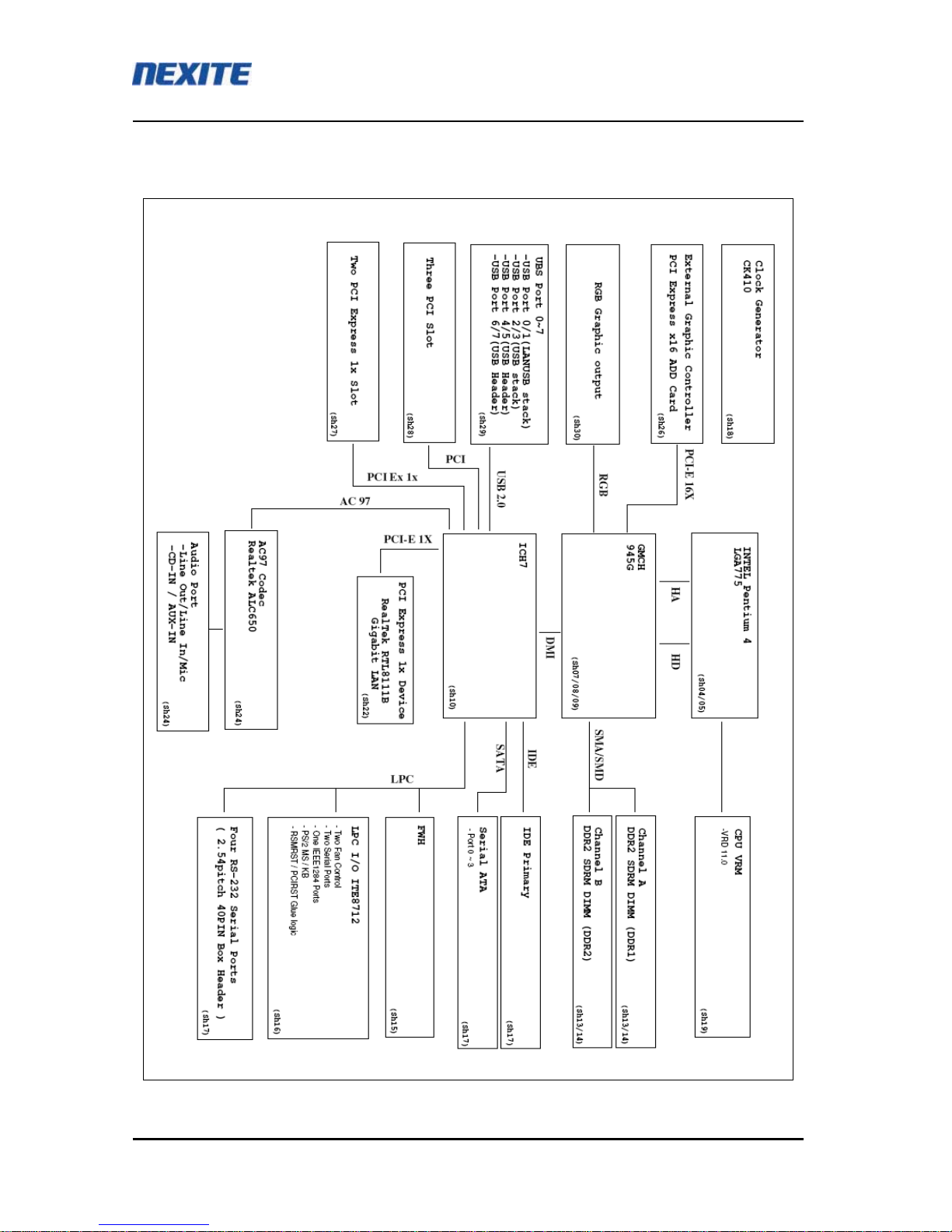
2. Functional Block Diagram
Hardware Document
nxtrdhw-001
Nexite, Inc. 7 /14 Revision 1.0
II. System Overview
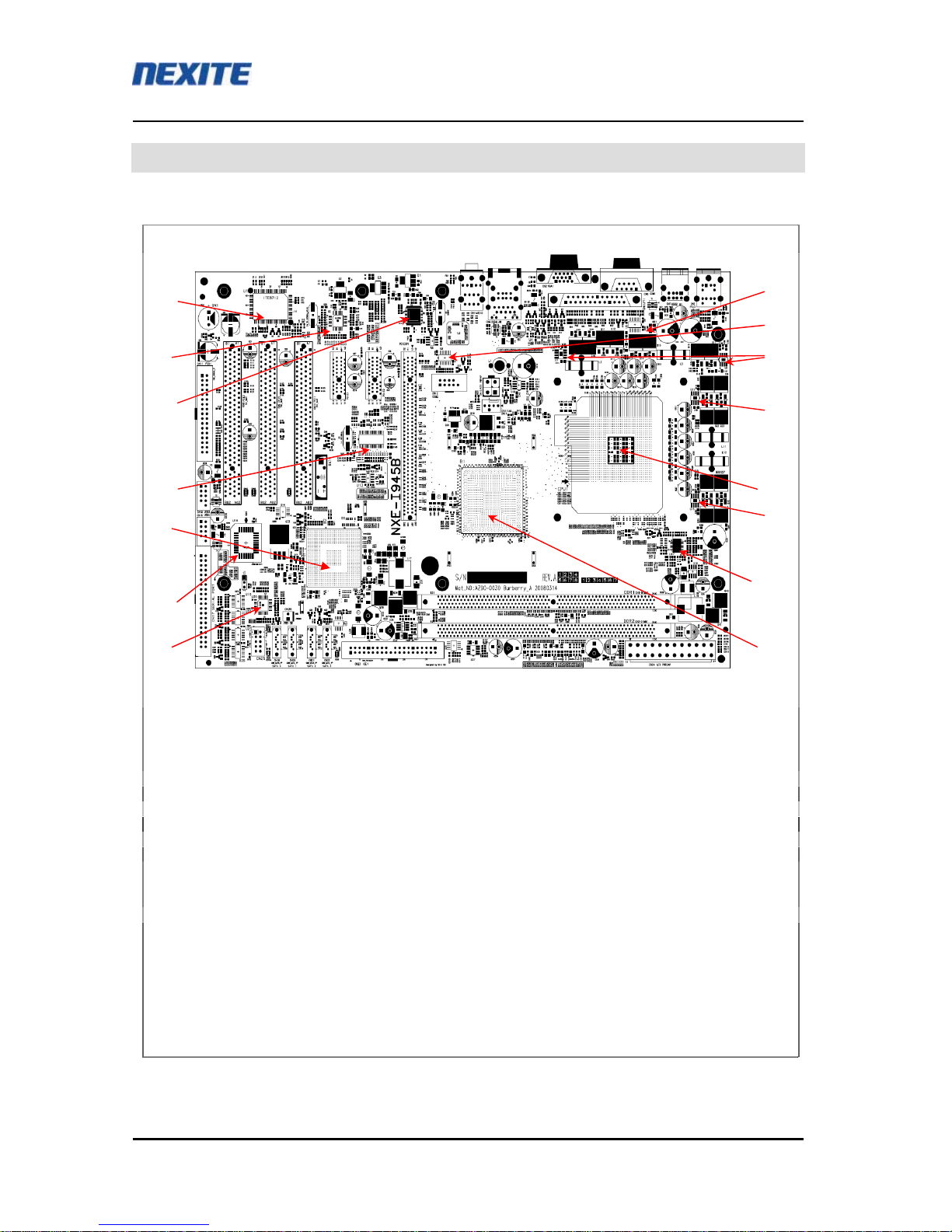
1. Burberry Mother-Board
1. CPU : LGA775 Pentium4 and Pentium-D Processor
2. North Bridge : Intel QG82945G GMCH BGA
3. South Bridge : Intel NH82801GR ICH7R BGA-652
4. FWH : Winbond W39V040FAPZ
5. LPC Super I/O : ITE8712F
6. Clock Generator : ICS 954101DGLF CK410 TSSOP
7. Gigabit LAN contr. : Realtek 8111B PCI Express Gigabit Ethernet controller
8. AC97 Codec : Realtek ALC650
9. RS232 Serial : GD75232
10. PWM FET Drivers : Intersil ISL6612AECBZ
11. PWM controller : Intersil ISL6556BCRZ 4-Phase PWM controller
12. LPC to Serial IC : Fintek F81216DG
5
8
7
9
11
1
9
4
3
6
2
10
10
10
12

Hardware Document
nxtrdhw-001
Nexite, Inc. 8 /14 Revision 1.0
2. Upgradeability
2-1. Processor
User can upgrade CPU
- Pentium 4 / Pentium-D / Core2Due / Celeron / Conroe-L
2-2. Memory
The Burberry motherboard has two Dual Inline Memory Module (DIMM), minimum 256MB to maximum 2GB
memory size. The BIOS detects the memory type, size, and speed through SMBUS interface between the core
chipset and DIMM module automatically.
The motherboard supports the following memory features
•Maximum memory size : 2GB
•Directly supports one or two channels of memory (each channel consisting of 64 data lines)
•Supports DDR2 400, DDR2 533, and DDR2 667
•Available bandwidth up to 5.3 GB/s (DDR2 667) for single-channel mode or dual-channel asymmetric mode
and 10.7 GB/s (DDR2 667) in dual-channel Interleaved mode.
•Supports DDR2 memory DIMM frequencies of 400MHz, 533MHz, and 667MHz. The speed used in all
channels is the speed of the slowest DIMM in the system.
•Supports 256-Mb, 512Mb, and 1-Gb DDR2 technologies for x8 and x16 devices.
•Supports four banks for all DDR2 devices up to 512-Mbit density
•DDR2-667 4-4-4 is Not supported
•Supports only unbuffered DIMMs
•SPD (Serial Presence Detect) scheme for DIMM detection support
•Supports configurations defined in the JEDEC DDR DIMM specification only
2-3 BIOS
θFlash memory (FWH) organization
The Burberry motherboard uses a AMI BIOS, which is stored in the flash memory and can be upgraded using
a disk-based or Windows-based program. An old version of the BIOS can be updated to the newer version
using the Flash Memory Update utility in a floppy diskette or HDD.

Hardware Document
nxtrdhw-001
Nexite, Inc. 9 /14 Revision 1.0
III. Jumpers , Connectors & Ports Descriptions
1. Board Jumpers Settings
1-1. Jumper Descriptions
Jumper Function 1-2 2-3 Remarks
J1 CMOS Clear Normal CMOS Clear
J1 1
Hardware Document
nxtrdhw-001
Nexite, Inc. 10 /14 Revision 1.0
2. I/O Headers , Slots & Connectors Descriptions
2-1. Motherboard Internal Connectors
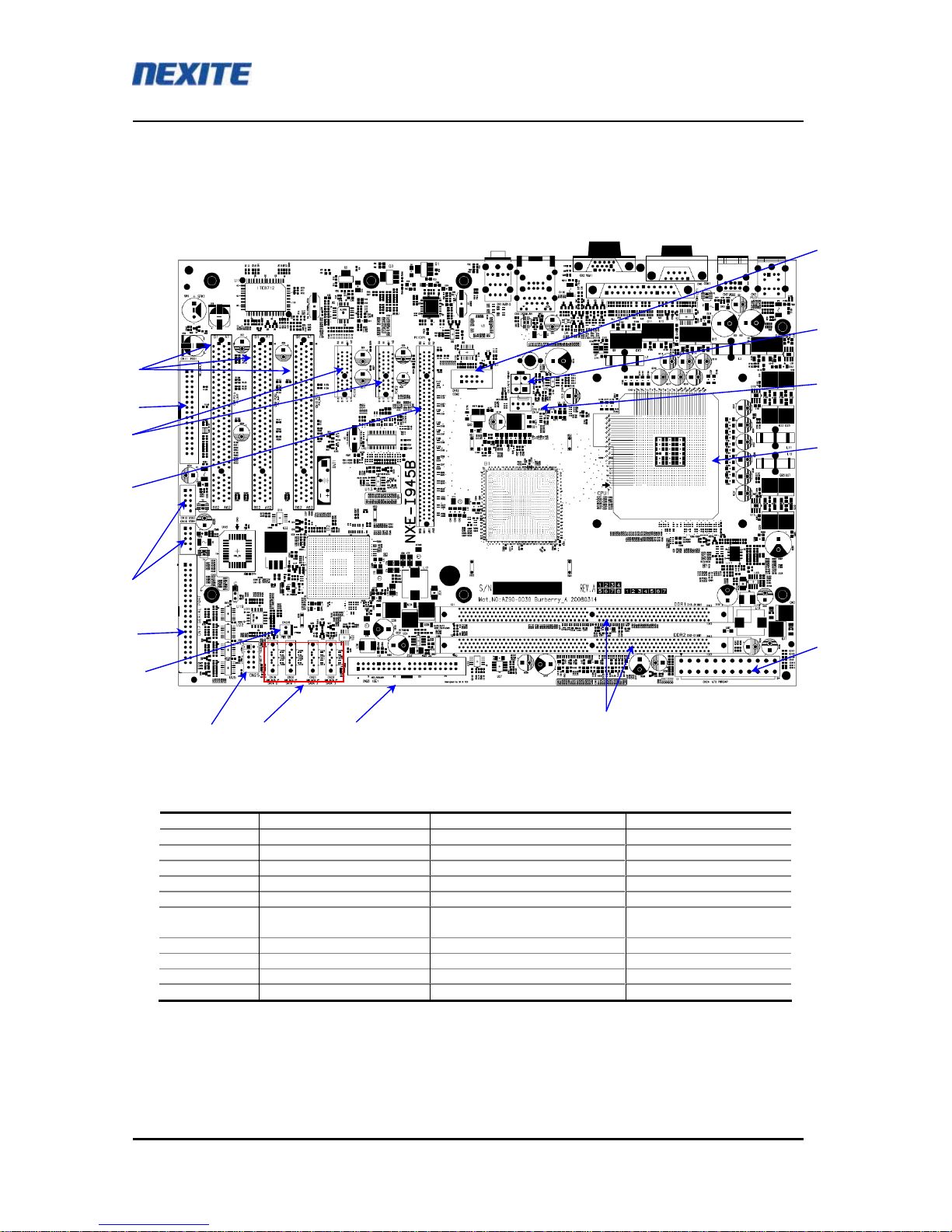
2-1-1. Main Connector, Slot & DIMM
No. Ref No. Description 1 Description 2
2 CN13 - CPU Power 4 pin
4 CPU1 - LGA775 CPU socket
5 CN24 - Main Power 24 pin
6 DDR1 ~ DDR2 U : DDR1 ÆDDR2 : D DDR2 DIMM slots
7 CN23 IDE1 IDE connector
8 CN19 ~ 22 L : CN19 ÆCN22 : R
L : SATA0 ÆSATA3 : R SATA II Connectors
12 PCIEXP1 - PCI express 16X slots
13 PCIE1 ~ PCIE2 L : PCIE1 ÆPCIE2 : R PCI express 1X slots
14 CN11 FDD1 FDD connector
15 CN8 ~ CN10 L : PCI3 ÆPCI1 : R PCI Slots
PWR Conn.
4
2
5
1
13
15
12
11
10
9 8 7 6
3
14
16

Hardware Document
nxtrdhw-001
Nexite, Inc. 11 /14 Revision 1.0
2-1-2. I/O Header & connectors
θ1: Serial interface connector (CN12 – COM2)
θ3 : CPU FAN connector (CN14)
Pin number Signal description
1 GND
2 +12V
3 FAN_Tacho output
4 FAN_CTL
θ9 : Front panel connector (CN25)
Pin number Signal description
1 -DCD
2 RXD
3 TXD
4 -DTR
5 GND
6 -DSR
7 -RTS
8 -CTS
9 -RI
10 KEY(NC)
Pin number Signal description
1 HDD_LED+
2 System_LED+
3 HDD_LED-
4 System_LED-
5 GND
6 GND
7 -PWR_ON
8 -System_RST
9 GND
10 NC
1 2 3 4
CN14
1 2
3 4
5 6
7 8
9 10

Hardware Document
nxtrdhw-001
Nexite, Inc. 12 /14 Revision 1.0
θ10 : Serial 4 Ports 40Pin Box Header (CN17)
Pin description Pin No. Pin description Port No.
DCD3 1 2 DSR3
RXD3 3 4 RTS3
TXD3 5 6 CTS3
DTR3 7 8 RI3
GND 9 10 N.C.
Serial Port 3
DCD4 11 12 DSR4
RXD4 13 14 RTS4
TXD4 15 16 CTS4
DTR4 17 18 RI4
GND 19 20 N.C.
Serial Port 4
DCD5 21 22 DSR5
RXD5 23 24 RTS5
TXD5 25 26 CTS5
DTR5 27 28 RI5
GND 29 30 N.C
Serial Port 5
DCD6 31 32 DSR6
RXD6 33 34 RTS6
TXD6 35 36 CTS6
DTR6 37 38 RI6
GND 39 40 N.C
Serial Port 6
Hardware Document
nxtrdhw-001
Nexite, Inc. 13 /14 Revision 1.0
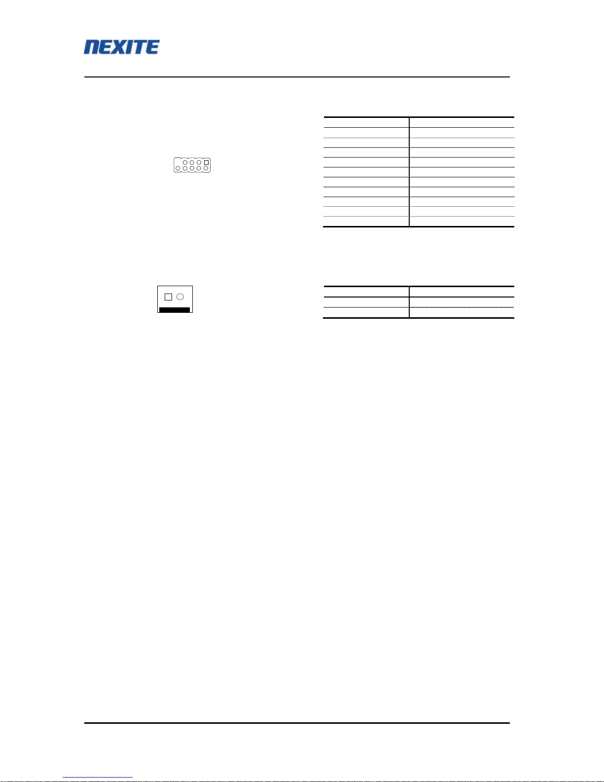
θ11 : USB2.0 interface connector(CN15, CN16)
θ16 : Power switch connector (CN26)
Pin number Signal description
1 VCC
2 USB-
3 USB+
4 GND
5 KEY
6 VCC
7 USB-
8 USB+
9 GND
10 GND
Pin number Signal description
1 -PWR_ON
2 GND
4 3 2 1
10 9 8 7 6

Hardware Document
nxtrdhw-001
Nexite, Inc. 14 /14 Revision 1.0
3. Rear Ports Description
No. Functions Description 1 Description 2
1 Line IN
2 Line OUT
3 Rear Audio Ports Microphone IN CN1
4 RJ-45 Gigabit LAN port
5 LAN USB Stack USB 2.0 X 2 ports CN4
6 Dsub15 VGA port CN2
7 Dsub25 parallel port CN5
8 D-Sub Ports Dsub9 Serial port CN6
9 USB Stack USB 2.0 X 2 ports CN7
10 Mini DIN connector PS2 Keyboard(D) Mouse(U) CN3
1
3
4
2
5 7
8
10
9
6
Table of contents
Other Nexite Motherboard manuals

 User manual")
Popular Motherboard manuals by other brands


MATSONIC
MATSONIC MS6393E user manual

Linear Technology
Linear Technology DC1842B manual

GIGA-BYTE TECHNOLOGY
GIGA-BYTE TECHNOLOGY GA-Z270X-Gaming 5 user manual

ASROCK
ASROCK PHANTOM GAMING Z790 RIPTIDE WiFi user manual

ON Semiconductor
ON Semiconductor NCS36000GEVB user manual

ICOP Technology
ICOP Technology ICOP-6036E user manual