Nexus NX Start Pack 1 User manual

Installation and Operation Manual
NX Start Pack 1
English

Start pack 1 English
1

English Start pack 1
2
Edition: April 2007

Start pack 1 English
3
1Part specification ..............................................................................................................5
2Installation .........................................................................................................................7
2.1 Installing the instrument ...................................................................................................8
2.2 Installing the WSI-box ......................................................................................................9
2.3 Installing the Wind Transducer.........................................................................................9
2.3.1 IMPORTANT Installation information!....................................................................9
2.3.2 Location.................................................................................................................9
2.3.3 Mounting in the mast head....................................................................................9
2.3.4 Mounting the wind transducer step by step.........................................................10
2.4 Installing the Log and depth transducers .......................................................................11
2.4.1 Correct location of transducer .............................................................................11
2.4.2 Installing the through hull fittings.........................................................................13
3Installation .......................................................................................................................13
3.1 Bedding ..........................................................................................................................13
3.2 Installing.........................................................................................................................13
3.3 Checking for Leaks.........................................................................................................15
3.4 Installation in a Cored Fiberglass Hull............................................................................15
3.5 Electrical Installation.......................................................................................................17
4Pairing procedure of wind transducer .......................................................................... 18
5Winter storage and re-initialization ...............................................................................19
6First start..........................................................................................................................20
6.1 Initialising the instrument................................................................................................20
6.2 How to use the push-buttons of the Sea Data................................................................21
6.3 Instrument backlight .......................................................................................................22
7Function overview of the Sea Data................................................................................22
8SPEED functions.............................................................................................................23
SPEED main-function.................................................................................................................23
SPEED sub-functions.................................................................................................................23
TRIP LOG (TRP) ....................................................................................................................23
TOTAL LOG (LOG).................................................................................................................23
START TIMER (STA).............................................................................................................23
TIMER ....................................................................................................................................23
AVERAGE SPEED (AVS) ......................................................................................................23
MAXIMUM SPEED (MAX)......................................................................................................24
DEPTH (unit/DPT)..................................................................................................................24
BATTERY (BAT).....................................................................................................................24
TEMPERATURE (TMP) ......................................................................................................... 24
9DEPTH functions.............................................................................................................25
DEPTH main-function.................................................................................................................25
DEPTH sub-functions.................................................................................................................25
LIGHT CONTROL...................................................................................................................25
SHALLOW ALARM (SHA)......................................................................................................25
DEPTH ALARM (DEA)...........................................................................................................25
ANCHOR ALARM...................................................................................................................25
BOAT SPEED (BSP/unit).......................................................................................................25
Barometric pressure (unit/hPA)..............................................................................................25
9.1.1 TRUE WIND ANGLE (TWA)................................................................................25
9.1.2 APPARENT WIND ANGLE (TWA)......................................................................26
9.1.3 TRUE WIND SPEED TWS..................................................................................26
9.1.4 APPARENT WIND SPEED (AWS)......................................................................26
9.2 Set shallow (SHA) and depth alarm (DEA).....................................................................26
9.3 Set and turn on anchor alarm (ANC)..............................................................................26
9.4 Clear an alarm value ......................................................................................................26

English Start pack 1
4
9.5 Silencing an alarm ..........................................................................................................27
9.6 Turning OFF or ON an alarm..........................................................................................27
10 Customise your display ..................................................................................................28
10.1 Move and lock a sub-function....................................................................................28
10.2 Copy and lock a sub-function ....................................................................................28
10.3 Select power on function ...........................................................................................28
10.4 Cancel a moved or locked sub-function ....................................................................28
11 Calibration setting up the Sea Data instrument............................................................29
11.1 Calibration of speed C10...........................................................................................29
11.1.1 Return C10 (RET) ................................................................................................29
11.1.2 Unit for Speed, C11 (Unit KTS)............................................................................29
11.1.3 Calibration of Speed, C12 (1.25 CAL)..................................................................29
11.1.4 Damping of Speed, C13 (SEA) ............................................................................30
11.1.5 Unit for Depth readings, C14 (Unit m)..................................................................30
11.1.6 Adjust Depth readings, C15 ( - 00.0 ADJ)............................................................30
11.1.7 Unit for Temp readings, C16 (Unit°C) ..................................................................30
11.1.8 Adjustment of Temp reading,C17 (0°C TMP).......................................................31
11.1.9 Unit for Air Pressure, C18 (Unit hPA)...................................................................31
11.1.10 Unit for Wind Speed, C19 (Unit m/s)....................................................................31
11.1.11 Adjustment of Wind Angle, C20 (000° ADJ).........................................................31
11.1.12 Damping of Wind Readings, C21 (SEA LOW).....................................................31
11.1.13 Key beep setting, C22 (OFF KEY).......................................................................31
12 Maintenance and fault finding........................................................................................32
12.1 Maintenance..............................................................................................................32
12.2 Fault finding...............................................................................................................32
12.2.1 General fault finding.............................................................................................32
12.2.2 Fault - action.........................................................................................................33
12.2.3 Error messages....................................................................................................33
13 Specifications ..................................................................................................................34
13.1 Technical specifications Sea Data.............................................................................34
13.2 Technical specifications WSI-box..............................................................................34
14 Waranty.............................................................................................................................35

Start pack 1 English
5
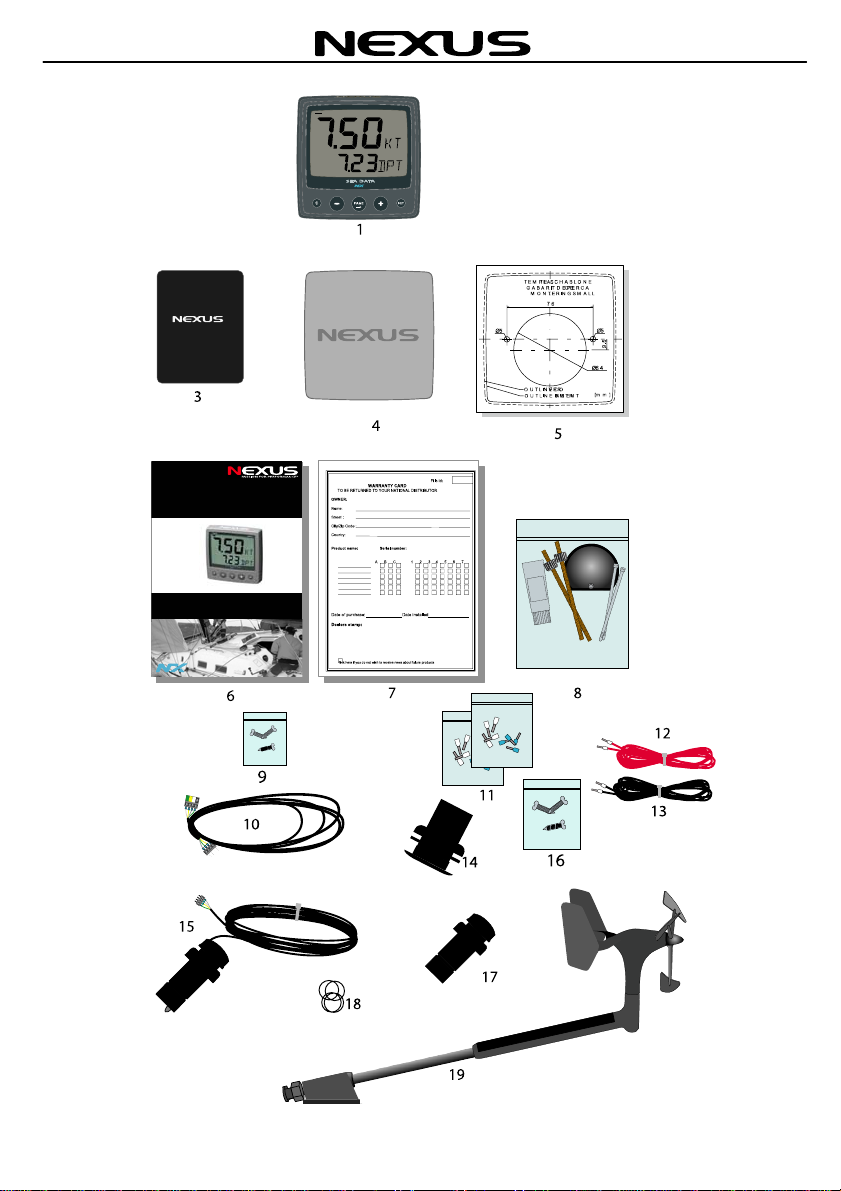
1 Part specification
___________________________________________________________
Items delivered with the instrument
Qty Description Reference
1 NX2 Sea Data instrument 1
1 WSI-box 3
1 Instrument cover 4
1 Drill template for instrument 5
1 Installation and operating manual 6
1 Warranty card 7
2 Instrument mounting screws 8
2 Plastic nuts 8
1 Connection back cover 8
2 Silicon paste tube 8
2 Plastic cable strap 8
3 Mounting screws for WSI-box 9
1 Nexus Network cable, 8 m (26 ft) 10
5 Cable protectors, 0,25 mm (0.1 inch) 11
5 Cable protectors, 0,75 mm (0.3 inch) 11
1 3m red power cable 12
1 3m black power cable 13
1 Through-hull fitting with nut 14
1 Tri-ducer TH52 15
3 Mounting screws for Wind transducer 16
1 Dummy plug 17
2 O-ring 18
1 Wireless wind transducer 19
1 Wind transducer bracket 19
Registering this product
Once you have checked that you have all the listed parts, please take time to fill in the
warranty document and return it to your national distributor.
By returning the warranty card, it will assist your distributor to give you prompt and
expert attention. Keep your proof of purchase. Also, your details are added to our
customer database so that you automatically receive new product catalogues when
they are released.
Warranty conditions see 14.
English Start pack 1
6
- Instrument -
Installation and Operation Manual
NX Sea Data
English

Start pack 1 English
7
2 Installation
• The installation includes 6 major steps:
1. Read the installation and operation manual.
2. Plan where to install the WSI-box, transducers and instruments.
3. Run the cables.
4. Install the WSI-box, transducers and instruments.
5. Learn the functions and calibrate your system.
Before you begin drilling ... think about how you can make the installation as neat
and simple as your boat will allow. Plan where to position the transducers, Server
and instruments. Think about leaving space for additional instruments in the future.
•A few ”do not” you should consider:
−Do not cut the cables too short. Allow extra cable length at the Server so it
can be disconnected for inspection without having to disconnect all
attached cables.
−Do not place sealant behind the display. The instrument gasket eliminates
the need for sealant.
−Do not run cables in the bilge, where water can appear.
−Do not run cables close to fluorescent light sources, engine or radio
transmitting equipment to avoid electrical disturbances.
−Do not rush, take your time. A neat installation is easy to do.
• The following material is needed:
Wire cutters and strippers.
Small and large Philips and small flat head screw driver.
Hole saw for the instrument clearance of 63 mm (2½").
Hole saw for the transducer of 51 mm.
2.8mm drill for the WSI-box mounting screws
5 mm (1/4") drill for the mounting holes.
Plastic cable ties
If you are doubtful about the installation, obtain the services of an experienced
technician.

English Start pack 1
8
2.1 Installing the instrument
•Place the adhesive drill template on the desired location for the instrument. Drill the
2 holes using a 5 mm (1/4") drill for the two pin bolts. Use a 63 mm (2½") hole saw
to machine the clearance hole for the instrument connection socket. Remove the
template.
•Screw the two pin bolts to the instrument
•Put the instrument in place
•Screw the two nuts from the back
Note! The two nuts must just be tighten by hand only
•Run the Nexus Network cable from the WSI-
box to the instrument.
•If you want to cut the Nexus Network cable to
length, disconnect 4-pole jack plug and cut
the cable. Peel off about 35 mm (1.4") of the
cable insulation. Remove about 6 mm (1/4")
from the 3 isolated wires (the 4th wire is an
earth / screen). Attach the 4 cable protectors
to the wires using a pair of flat pliers.
•Connect the 4 cable protectors to the 4-pole
jack plug as shown. Apply silicon paste on all
locations as shown.
Note: Must be done to avoid corrosion.
Silicon paste
Start pack 1 English
9
2.2 Installing the WSI-box
Remove the WSI-box cover from the base plate by removing the
screw. Drill the 3 screw holes using a 2.8 mm (0.11") drill. Mount
the WSI-box using the 3 mounting screws.
Apply silicon paste on the screw terminal. Connect the 8 m Nexus
Network cable supplied with cable protectors to the WSI-box on
pins 13, 14, 15, and 16. Match the colour codes for each wire.
2.3 Installing the Wind Transducer
2.3.1IMPORTANT Installation information!
BEFORE placing the wind transducer on the mast, a pairing
procedure must be done!
2.3.2Location
The transducer should be mounted on a horizontal surface in the mast head. If the
masthead is not horizontal a shim has to be added. A 15 shim for Seldén masts is
available (art.no 67400-15).
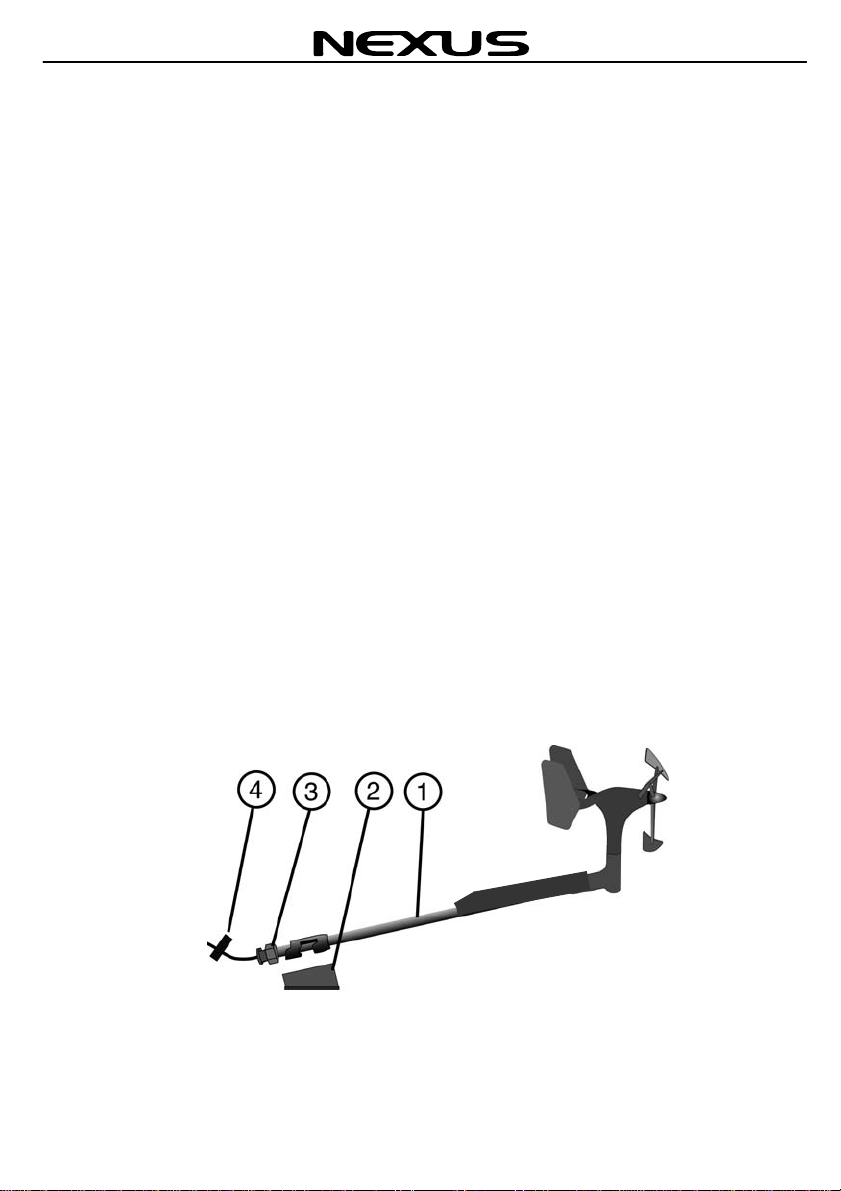
2.3.3Mounting in the mast head
The transducer permits any type of horizontal mounting angle.
Mount the unit by directing the pipe (1) down and backwards in the bracket (2). Secure
the nut (3) towards the attachment BY HAND (tools can be needed when demounting).
Attach the security clamp (4) behind the nut.
Table of contents
Other Nexus Controllers manuals


Popular Controllers manuals by other brands

Digiplex
Digiplex DGP-848 Programming guide

YASKAWA
YASKAWA SGM series user manual

Sinope
Sinope Calypso RM3500ZB installation guide

Isimet
Isimet DLA Series Style 2 Installation, Operations, Start-up and Maintenance Instructions

LSIS
LSIS sv-ip5a user manual

Rockwell Automation
Rockwell Automation 1769-L31 installation instructions


