NI ISC-178 Series User manual

USER MANUAL
ISC-178x
Monochrome/Color Smart Camera
This document contains detailed electrical and mechanical information for the National
Instruments ISC-178x.
Contents
Hardware Overview.................................................................................................................. 1
Connector Pinouts............................................................................................................. 3
LED Indications................................................................................................................ 8
Mounting the ISC-178x.................................................................................................... 9
Connecting to Lighting Devices............................................................................................. 12
Wiring the Isolated Inputs....................................................................................................... 13
Wiring the Isolated Outputs.................................................................................................... 14
Choosing a Pull-up Resistor....................................................................................................16
Safe Mode (NI Linux Real-Time)...........................................................................................16
Image Sensor...........................................................................................................................16
Acquiring Images....................................................................................................................20
Triggering........................................................................................................................20
Exposure and Lighting.................................................................................................... 24
Image Readout................................................................................................................ 25
Trigger Overlap............................................................................................................... 25
Reconfiguring During an Acquisition.............................................................................26
ISC-178x Software Attributes.................................................................................................26
Restoring the NI Linux Real-Time Operating System............................................................35
Restoring the Windows Operating System............................................................................. 36
Creating a Bootable USB Flash Drive............................................................................ 36
Reinstalling Windows..................................................................................................... 37
Where to Go Next................................................................................................................... 38
Worldwide Support and Services............................................................................................ 38
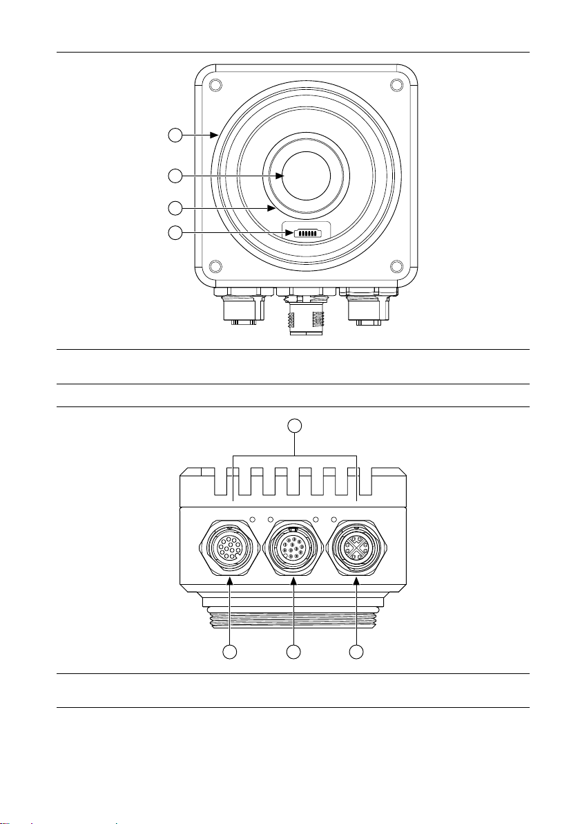
Hardware Overview
ISC-178x smart cameras incorporate a 1.58 GHz dual-core Intel Celeron processor, image
sensor, and digital I/O in a compact, IP67-rated housing.

Figure 1. ISC-178x Front
1
3
4
2
1. Lens cover mount
2. Image sensor
3. C-mount lens mount
4. Varioptic liquid lens connector
Figure 2. ISC-178x Connectors
Power Status User 100/1G
1
2 3 4
1. LED indicators
2. Digital I/O and Power connector
3. VGA and USB connector
4. Network connector
2| ni.com | ISC-178x User Manual

Connector Pinouts
The ISC-178x provides the following connectors.
Power and I/O Connector
The Power and I/O connector is a 12-pin female M12 connector that provides power to the
camera and transmits digital I/O signals.
In addition, the connector has a specialized analog dimmer output intended to be used with
Advanced Illumination lighting devices.
Related Information
Connecting to Lighting Devices on page 12
Wiring the Isolated Inputs on page 13
Wiring the Isolated Outputs on page 14
ISC-178x Power and I/O Connector Pinout
1
2
3
4
5
6
78
9
10
11
12
Table 1. ISC-178x Power and I/O Connector Signal Descriptions
Pin Signal Description
1 C OUT Common reference (negative) for isolated outputs
2 Analog Out Analog reference output for lighting controller
3 Iso Out 2+ General-purpose isolated output (positive)
4 V System power voltage (24 VDC ± 10%)
5 Iso In 0 General-purpose isolated input
6 C IN Common reference (positive or negative) for isolated inputs
7 Iso In 2 General-purpose isolated input
8 Iso In 3 (NI Linux Real-Time) Reserved for safe mode
(Windows) General-purpose isolated input
9 Iso In 1 General-purpose isolated input
ISC-178x User Manual | © National Instruments | 3

Table 1. ISC-178x Power and I/O Connector Signal Descriptions (Continued)
Pin Signal Description
10 Iso Out 0+ General-purpose isolated output (positive)
11 C System power and analog reference common
12 Iso Out 1+ General-purpose isolated output (positive)
The following NI power and I/O cables are available for the ISC-178x.
Table 2. Power and I/O Cables
Cables Length Part Number
A-Code M12 to A-Code M12 Power and I/O Cable 3 m 145232-03
A-Code M12 to Pigtail Power and I/O Cable 3 m 145233-03
A-Code M12 to Pigtail Power and I/O Cable
The A-Code M12 to Pigtail Power and I/O Cable (NI part number 145233-03) provides power
to the NI ISC-178x smart camera and transmits digital I/O signals.
Figure 3. A-Code M12 to Pigtail Power and I/O Cable Pinout
1
2
3
4
5
6
78
9
10
11
12
Table 3. A-Code M12 to Pigtail Power and I/O Cable Wire Designations
Pin Signal Color
1 COUT Brown
2 Analog Out Blue
3 Iso Out 2+ White
4 V Green
5 Iso In 0 Pink
4| ni.com | ISC-178x User Manual

Table 3. A-Code M12 to Pigtail Power and I/O Cable Wire Designations (Continued)
Pin Signal Color
6 CIN Yellow
7 Iso In 2 Black
8 Iso In 3 Gray
9 Iso In 1 Red
10 Iso Out 0+ Violet
11 C Gray/pink
12 Iso Out 1+ Red/blue
VGA and USB Connector
The VGA and USB connector is a 12-pin male M12 connector that provides connectivity
between the ISC-178x, a display device, and USB 2.0 devices like a keyboard or a mouse.
ISC-178x VGA and USB Connector Pinout
11
10
12
4
32
1
9
8
7
6
5
Table 4. ISC-178x USB and VGA Connector Signal Descriptions
Pin Signal Description
1 VBUS USB power (+5 VDC)
2 D+ USB Data +
3 D- USB Data -
4 GND Ground for USB power
5 RED Red analog video signal
6 BLUE Blue analog video signal
ISC-178x User Manual | © National Instruments | 5

Table 4. ISC-178x USB and VGA Connector Signal Descriptions (Continued)
Pin Signal Description
7 VSYNC Vertical synchronization signal
8 HSYNC Horizontal synchronization signal
9 GREEN Green analog video signal
10 GND VGA ground reference
11 GND VGA ground reference
12 GND VGA ground reference
The following NI USB and VGA cable is available for the ISC-178x.
Table 5. USB and VGA Cable
Cables Length Part Number
M12 to VGA/USB Splitter Cable 1 m 782022-01
Network Connector
The network connector is an 8-pin M12 X-coded connector that provides connectivity between
the ISC-178x and a computer or network.
ISC-178x Network Connector Pinout
12
3
4
5
6
7
8
Table 6. ISC-178x Network Connector Signal Descriptions
Pin Fast Ethernet (100 Mbps) Gigabit Ethernet
MDI MDI-X
1 TX+ BI_DA+ BI_DB+
2 TX- BI_DA- BI_DB-
3 RX+ BI_DB+ BI_DA+
6| ni.com | ISC-178x User Manual

Table 6. ISC-178x Network Connector Signal Descriptions (Continued)
Pin Fast Ethernet (100 Mbps) Gigabit Ethernet
MDI MDI-X
4 RX- BI_DB- BI_DA-
5 No Connect BI_DD+ BI_DC+
6 No Connect BI_DD- BI_DC-
7 No Connect BI_DC- BI_DD-
8 No Connect BI_DC+ BI_DD+
The following NI network cables are available for the ISC-178x.
Table 7. Network Cables
Cables Length Part Number
X-Code M12 to RJ45 Network Cable 5 m 145230-05
X-Code M12 to X-Code M12 Network Cable 5 m 145231-05
Varioptic Liquid Lens Connector
The ISC-178x supports the following models of Varioptic liquid lenses.
• Caspian C-39N0-160-I2C
• Caspian C-39N0-250-I2C
Refer to the ISC-178x Getting Started Guide for installation instructions.
ISC-178x Varioptic Liquid Lens Connector Pinout
123456
Table 8. ISC-178x Varioptic Liquid Lens Connector Signal Descriptions
Pin Signal Description
1 Power Power supply (+5 V)
2 Ground Ground
3 SDA Serial data line
ISC-178x User Manual | © National Instruments | 7

Table 8. ISC-178x Varioptic Liquid Lens Connector Signal Descriptions (Continued)
Pin Signal Description
4 SCL Serial data clock
5 Unused Unused
6 Unused Unused
LED Indications
The ISC-178x indicates specific error conditions by flashing the Power, Status, and User
LEDs.
Table 9. LED Indications
Power
LED
Status LED User LED Indication
Off Off Off The ISC-178x does not have power.
Red Red Red The ISC-178x is powered, but is not responding.
Red — Orange Initialization error.
Orange — Orange/Red
blink
Temperature limit exceeded.
Orange Orange/Red
blink
Orange System firmware initializing.
Orange Orange/Red
blink
Green System firmware initialization completed.
Green Orange/Red
blink
Off Sensor driver not loaded. Possible reasons:
• Operating system loading
• ISC-178x is booted in safe mode
(NI Linux Real-Time only)
• NI-IMAQdx Smart Camera Support is not
installed
Green Orange User defined
(default is
Off)
The ISC-178x is ready to use. The sensor driver
is idle.
Green Green User defined
(default is
Off)
The ISC-178x is ready to use. The sensor driver
is in use.
8| ni.com | ISC-178x User Manual

Mounting the ISC-178x
The ISC-178x must be mounted to a support using the provided mounting holes before
operating.
Note The acceptable bend radius for all connected cables is ten times (10x) the
cable diameter.
The following figures provide dimensional drawings for the ISC-178x.
Figure 4. Front View with Dimensions
42.00 mm
(1.654 in.)
21.00 mm
(.827 in.)
16.50 mm
(.650 in.)
61.00 mm
(2.402 in.)
61.00 mm
(2.402 in.)
75.00 mm
(2.953 in.)
7.00 mm
(.276 in.)
7.00 mm
(.276 in.)
37.50 mm
(1.476 in.)
37.50
mm
(1.476
in.)
M4X0.7 – 6H
3.50
mm
(0.138
in.)
75.00 mm
(2.953 in.)
ISC-178x User Manual | © National Instruments | 9

Figure 5. Back View with Dimensions
7.00 mm
(
.276 in.)
91.00 mm
(
3.583 in.)
61.00
mm
(2.402
in.)
87.55 mm
(3.447
in.)
46.50 mm
(1.831
in.)
7.00
mm
(.276
in.)
M4X0.7 – 6H
4.00 mm (0.157 in.)
Figure 6. Side View with Dimensions
46.00 mm
(1.811 in.)
72.00 mm
(2.834 in.)
REF.
10 | ni.com | ISC-178x User Manual

Figure 7. Side View with Dimensions
26.50 mm
(1.043 in.)
41.00 mm
(1.614 in.)
118.00 mm
(4.646 in.)
REF.
Figure 8. Bottom View with Dimensions
Power Status User 100/1G
17.10 mm
(.673 in.)
54.00 mm
(2.126 in.)
24.00 mm
(.945 in.)
2X 6.00
mm (
.236
in.)
ISC-178x User Manual | © National Instruments | 11

Connecting to Lighting Devices
The Power and I/O connector has a specialized analog dimmer output intended to be used with
the Advanced Illumination Inline Control System 3 (ICS 3) or ICS 3S for continuous or
strobed lighting operations.
Related Information
Triggering on page 20
External Trigger on page 21
Power and I/O Connector on page 3
Wiring a Lighting Device for Continuous Mode
The following figure shows how to wire the ISC-178x and an Advanced Illumination ICS 3
lighting controller without a trigger. Use this configuration to run a light in continuous mode.
Figure 9. Wiring a Lighting Controller Without a Trigger
24 VDC
Supply
ICS 3 Lighting
Device
ISC-178x
Trigger
+
–
Analog Out Analog
C
+
–
Wiring a Lighting Device for Strobe Mode
The following figure shows how to wire the ISC-178x and an Advanced Illumination ISC 3
lighting controller using an isolated output as a trigger. Use this configuration to run a light in
strobe mode. This configuration requires that the isolated outputs and system power share the
same ground.
12 | ni.com | ISC-178x User Manual

Figure 10. Wiring a Lighting Controller Using an Isolated Output as Trigger
2 kΩ
0.5 W
24 VDC
Supply
ICS 3 Lighting
Device
ISC-178x
Iso Out Trigger
+
–
Analog Out Analog
C
COut
+
–
Note A different pull-up resistor may be used, as long as the isolated output sink
current specification is not exceeded and the resistor is appropriately rated for the
expected power dissipation.
Related Information
Choosing a Pull-up Resistor on page 16
Wiring the Isolated Inputs
The isolated inputs can be configured as current sinking or current sourcing. The configuration
depends on whether the common input signal is tied to ground (sinking input) or +V (sourcing
input). The isolated inputs cannot be configured individually. The isolated inputs must all be
sinking or must all be sourcing.
Related Information
Power and I/O Connector on page 3
Wiring an Isolated Input to a Sinking Output
The following figure shows how to wire the isolated inputs with a sourcing configuration to a
sinking output. The isolated inputs on the ISC-178x have a built-in current-limiting circuit.
The isolated inputs do not require a current-limiting resistor. Refer to the specifications of the
connected output device to determine if a resistor is needed to limit the output current.
ISC-178x User Manual | © National Instruments | 13

Figure 11. Wiring an Isolated Input to a Sinking Output
External
Power Supply
Sinking Output
Device
ISC-178x
Iso In
CIn
+
–
Wiring an Isolated Input to a Sourcing Output
The following figure shows how to wire the isolated inputs with a sinking configuration to a
sourcing output.
Figure 12. Wiring an Isolated Input to a Sourcing Output
External
Power Supply
Sourcing Output
Device
ISC-178x
Iso In
CIn
+
–
Wiring the Isolated Outputs
The isolated outputs can be wired to a sourcing input or sinking input.
Related Information
Power and I/O Connector on page 3
Wiring an Isolated Output to a Sinking Input
The following figure shows how to wire an isolated output to a sinking input.
14 | ni.com | ISC-178x User Manual

Figure 13. Wiring an Isolated Output to a Sinking Input
2 kΩ
0.5 W
External
Power Supply
Sinking Input
Device
ISC-178x
Iso Out
COut
+
–
Note A different pull-up resistor may be used, as long as the isolated output sink
current specification is not exceeded, the sinking input device specifications are met,
and the resistor is appropriately rated for the expected power dissipation. Refer to
the documentation for the sinking input device for additional requirements.
Related Information
Choosing a Pull-up Resistor on page 16
Wiring an Isolated Output to a Sourcing Input
The following figure shows how to wire an isolated output to a sourcing input.
Figure 14. Wiring an Isolated Output to a Sourcing Input
External
Power Supply
ISC-178x
Iso Out
COut
+
–
Sourcing Input
Device
Note Choose a resistor value that does not exceed the output sink current
specification of the isolated output. The value of the resistor depends on the current-
limiting characteristics of the sourcing input device. A resistor may not be needed if
the current is sufficiently limited by the input device.
Related Information
Choosing a Pull-up Resistor on page 16
ISC-178x User Manual | © National Instruments | 15

Choosing a Pull-up Resistor
Choose a pull-up resistor that does not exceed the maximum current sink rating of the isolated
outputs. The pull-up resistor must have a power rating that will not cause it to overheat.
For example, with a 24 V output, a 2 kΩ resistor will cause a current sink of 24 V / 2 kΩ = 12
mA. This leads to a power consumption in the resistor of 12 mA × 24 V = 0.288 W. In this
example, a 0.5 W resistor would be recommended. Because 12 mA is less than the current sink
rating, a 2 kΩ, 0.5 W resistor would be acceptable.
The resistor value also affects the rise time of the output. For example, a 1 kΩ resistor will rise
more quickly than a 2 kΩ resistor, but the 1 kΩ resistor will consume more power and require
a resistor with a higher power rating.
Related Information
Wiring a Lighting Device for Strobe Mode on page 12
Wiring an Isolated Output to a Sinking Input on page 14
Wiring an Isolated Output to a Sourcing Input on page 15
Safe Mode (NI Linux Real-Time)
When you boot the ISC-178x into safe mode, it launches only the services necessary for
updating its configuration and installing software. Connect the Iso In 3 and CIN signals of the
ISC-178x as shown in the following figure, then apply power to boot into safe mode.
Figure 15. Booting into Safe Mode
ISC-178x
Iso In 3
CIN
C
VExternal
Power Supply
+
–
Image Sensor
This section provides an overview of the ISC-178x image sensors, field of view, and imaging
settings.
All models of the ISC-178x use ON Semiconductor Python NOIP1SN or NOIP1SE sensors.
ISC-178x are available with the following resolution configurations.
16 | ni.com | ISC-178x User Manual

Table 10. ISC-178x Resolution Configurations
Model Resolution
ISC-1780 640 x 480
ISC-1781 1280 x 1024
ISC-1782 1920 x 1200
ISC-1783 2592 x 2048
Field of View
The field of view is the area under inspection that will be imaged by the ISC-178x. It is critical
to ensure that the field of view of your system includes the object you want to inspect.
To calculate the horizontal and vertical field of view (FOV) of your imaging system, use the
following equation. All models of the ISC-178x have square pixels that are 4.8 µm on each
side. Use that value for the Pixel Pitch. The Active Pixels can be obtained from the image
sensor configuration table or the specifications for each model.
= ℎ × ×
ℎ
where
FOV is the field of view in either the horizontal or vertical direction,
Pixel Pitch measures the distance between the centers of adjacent pixels in either the
horizontal or vertical direction,
Active Pixels is the number of pixels in either the horizontal or vertical direction,
Working Distance is the distance from the front element (external glass) of the lens to
the object under inspection, and
Focal Length measures how strongly a lens converges (focuses) or diverges (diffuses)
light.
The following figure illustrates horizontal field of view and working distance.
ISC-178x User Manual | © National Instruments | 17

Figure 16. Parameters of an Imaging System
2
1
3
1. Horizontal Imaging Width
2. Working Distance
3. Horizontal Field of View
For example, if the working distance of the imaging setup is 100 mm, and the focal length of
the lens is 8 mm, then the field of view in the horizontal direction of an ISC-1780 is
ℎ =0.0048 × 640 × 100
8 = 38.4
The field of view in the vertical direction is
ℎ =0.0048 × 480 × 100
8 = 28.8
Based on the results of these two equations, you can adjust the various parameters until you
achieve the right combination of components that match your inspection needs. This might
include increasing the working distance, choosing a lens with a shorter focal length, or
changing to a higher resolution camera.
Related Information
Exposure and Lighting on page 24
Image Readout on page 25
Gain
Gain is a multiplier applied to the analog signal prior to digitization. Increasing the gain
increases the amplitude of the signal. Gain allows you to trade off between making smaller
signals more visible at the cost of increased noise and no longer being able to differentiate
18 | ni.com | ISC-178x User Manual

between larger signals. For most applications, the ISC-178x default gain setting optimizes the
balance between small signals and large signals.
Figure 17. Effect of Gain on the Video Signal
255
Pixel Value
255
Pixel Value
255
Pixel Value
A. B. C.
1. Low Gain
2. Medium Gain
3. High Gain
In figure A, low gain has been applied to the signal. The pixel values in the image are grouped
close together. In figure B, medium gain has been applied to the signal. There are now more
notable differences in pixel value within the image. In figure C, high gain has been applied to
the signal. At high gain, mid-range and bright portions of the image are now both represented
as white, the highest pixel value. In figure C, several bright areas of the image have been
clipped to the maximum pixel value, and you can no longer distinguish subtle shading in the
brightest areas of the image.
Gain can be useful when there is not enough available light and you need to increase the
brightness of images. However, increasing gain multiplies both the signal and noise. When
possible, it is preferable to add additional lighting.
Auto White Level (Color Models Only)
Color models of the ISC-178x allow you to adjust the gain for each color plane in the RGB
color space. The white level specifies the point at which values in the red, green, and blue
color planes converge to produce white. To obtain an accurate white level, either adjust each
gain value manually or use automatic white level adjustment with a test image. For best results
the image should contain a neutral reference, such as a gray piece of paper or a reference card.
There are multiple ways to adjust gain values or enable automatic white balance adjustment:
• MAX—Use the settings on the Color tab of the device configuration page to adjust gain
levels or enable automatic white level adjustment.
• Vision Builder AI—Use the settings on the Color tab of the Acquire Image (Smart
Camera) step to adjust gain levels or enable automatic white level adjustment.
Black Level
The black level specifies the image brightness. Set the black level to the pixel value which
corresponds to true black. If the black level is inaccurate, near-black pixels may be displayed
as black or black objects may appear gray in the output image.
ISC-178x User Manual | © National Instruments | 19

There are multiple ways to adjust the black level:
• MAX—Use the settings on the Camera Attributes tab of the device configuration page.
• Vision Builder AI—Use the settings on the Advanced tab of the Acquire Image (Smart
Camera) step.
Look-up Table
A look-up table (LUT) transformation maps pixel values in the source image into other values
in the transformed image. For example, you can use a LUT transformation to improve the
contrast and brightness of an image. Color models of the ISC-178x allow you to define a LUT
for each color plane in the RGB color space.
To enable a LUT in MAX, use the LUT Controls on the Camera Attributes tab of the device
configuration page. Vision Builder AI does not support LUT editing for the ISC-178x.
Image Sensor Maintenance
Do not touch the image sensor by hand or with other objects. The sensor can be damaged by
electrostatic discharge (ESD), body oils, and particulate matter.
Use a lens mount cover whenever a lens is not mounted on the camera to protect the sensor
from dust and dirt.
Avoid drastic temperature changes to prevent dew condensation.
When necessary, use the following procedure to clean the sensor at a workstation equipped
with anti-ESD facilities. If dust sticks to the sensor, first attempt to blow it off from the side of
the sensor using ionized air. If oils are present on the sensor, clean the sensor with a cotton bud
and ethyl alcohol. Be careful not to scratch the glass. Use only one pass over the glass per
cotton bud to minimize the risk of recontamination and scratching.
Acquiring Images
This section contains information about the main components of acquiring images with the
ISC-178x—triggering, exposure and lighting, and image readout—and explains the
relationships between them.
Triggering
You can configure the ISC-178x to acquire images based on internal timing or an external
trigger signal. When using internal timing, the ISC-178x will trigger the acquisition using an
on-board clock that runs at a constant rate. Once the acquisition is started, images will be
acquired without any external stimulus. When using external triggering, the acquisition of each
frame is tied to the occurrence of the configured external event. The rate of the acquisition is
determined by the rate of the external event. In both cases, the ISC-178x can acquire images at
up to the maximum frame rate.
Related Information
Connecting to Lighting Devices on page 12
Determining the Maximum Frame Rate on page 22
20 | ni.com | ISC-178x User Manual
Table of contents
Other NI Machine Vision System manuals
Popular Machine Vision System manuals by other brands

e-con Systems
e-con Systems See3CAM 130 Getting started manual

opto engineering
opto engineering COE-G Series user manual

Cognex
Cognex In-Sight 8000 Series manual

Cognex
Cognex In-Sight 2000 manual

Allied Vision Technologies
Allied Vision Technologies Vimba C API Programmer's manual

Omron
Omron Vision Sensor FH Series Connection guide