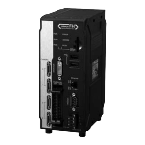
Panasonic IMAGECHECKER PV230 User manual

7
I
Panasonic
®
P 四O
Manual

Before Reading This Manual
Thank you for purchasing the IMAGECHECKER PV230.
This manual describes the functions of PV230 Character Recognition Checker and
Code Reader Checker, and the setting methods.
To ensure that you use this product correctly, read this User's Manual together with
the PV200 User's Manual thoroughly before use for the details of the hardware and
other functions than Character Recognition and Code Reader. Make sure that you fully
understand the product and information on safe.
Safety Precautions
To ensure that you use this product correctly, read this User’s Manual thoroughly before
use. Make sure that you fully understand the product and information on safe.
WARNING
Critical situations that could lead to user’s death or serious injury are assumed by
mishandling of the product:
•Do not use this product in areas with inflammable gas. It could lead to an explosion.
•Exposing this product to excessive heat or open flames could lead to damage to the lithium
battery or other electronic parts.
•Do not store a lens in the locations subject to direct sunlight. It could lead to smoke
generation.
•Do not look at the sun through a lens. It could lead to blindness.
•Always take precautions to ensure the overall safety of your system, so that the whole system
remains safe in the event of failure of this product or other external factor.
CAUTION
Critical situations that could lead to user’s injury or only property damage are assumed by
mishandling of the product:
•Do not dismantle or remodel the product. It could lead to excessive exothermic heat or smoke
generation.
•Do not touch the terminal while turning on electricity. It could lead to an electric shock.
•Do not allow foreign matters such as liquid, flammable materials, metals to go into the inside
of the product. It could lead to excessive exothermic heat or smoke generation.
•Do not bend the cables forcibly, place a heavy object on them or bring them close to a thermal
appliance. It could lead to an electric shock or smoke generation.
•To prevent excessive exothermic heat or smoke generation, use this product at the values
less than the maximum of the characteristics and performance that are assured in these
specifications.
•Use the external devices to function the emergency stop and interlock circuit.
•Connect the wires or connectors securely. The loose connection could lead to excessive
exothermic heat or smoke generation.
•Do not undertake construction (such as connection and disconnection) while the power supply
is on. It could lead to an electric shock.

i
Introduction
Thank you for purchasing Panasonic Industrial Devices SUNX's IMAGECHECKER PV230.
Please read this Instruction Manual carefully and thoroughly for the correct, optimum and safe use of this
product.
All our products are strictly inspected before shipped. However, before using this product, check for problems
that occurred during transport and then perform operation check. If the product is found to be damaged or does
not operate as specified, we are sorry to trouble you, but please contact the shop where you purchased the
product or our nearest local office to you.
Manual Configuration
The following manuals have been prepared for this product. Go through these manuals according to the
objectives and use them fully. Keep the manuals at hand after reading over so that you can see them
whenever necessary.
IMAGECHECKER PV230 Manual Operation Edition (This description)
Describes items necessary for operating the PV230.
If you need the booklet, please contact our
personnel in charge of sales.
•OCR Checker
• Code Reader Checker
•Communication Commands
•Preset menu
For the hardware information and the functions other than OCR Checker and Code Reader Checker, please
refer to the PV200 Manual.
IMAGECHECKER PV200 Manual Operation Edition
Describes items necessary for operating the PV200. Use this manual for preprocessing functions and
procedure for setting inspection conditions of various checkers. If you need the booklet, please contact
our personnel in charge of sales.
• Procedure for setting inspection conditions with various checkers used
(except for Optical Character Reader (OCR) checker and code reader checker)
•Operation and procedure for setting RUN Menu
• Environment Setting
• Tool Setting (Configuration change)
•Debugging of main unit (Inspection re-examination function)
•Select Menu
•Communication Settings
• Tool software for PC
• Specification and Part No. List

ii
Precautions When Using Network Function
There is the risk of suffering following damage when a system using this product is used via a global
network.
(1) Information leakage through this unit
(2) Illegal operations by a malicious third party
(3) Obstructing or stopping by a malicious third party
Sufficient network security measures should be taken including the following measures at your own risk to
prevent such damages.
•Use the system via a network whose safety is secured by a firewall, etc.
•For a system using a computer, perform the check for virus and malicious program infections, and eliminate
them.
•Set a user name and password, and restrict users who can log in the computer to protect the system from
unauthorized attack.
•There is a possibility that information such as image data, authentication information (user name, password),
alarm mail information, FTP server information and DDNS server information is leaked. Take measures such
as restricting access by user authentication.
•Change the password of NAS (FTP server) periodically.
•Do not install the system in a place where cables, etc. can be easily damaged or altered.
•It is recommended to use the system via VPN (Virtual Private Network) or under the environment in which a
dedicated line network is built to enhance security furthermore.
Symbol Indications
Describes the details of its part or useful things.
Describes things that need to be paid special attention when operating the product.
Indicates the reference including the details related to its part.

iii
Table of Contents
Manual Configuration..........................................i
Symbol Indications.............................................ii
Table of Contents..............................................iii
List of menus.....................................................iv
1 Preset Menu....................................... 7
1.1 Preset Menu................................................................8
1.2 Descriptions of Preset Menu.....................................9
1.3 Editing Preset Menu..................................................11
1.4 Using Preset Menu with Other Type Numbers or
After Switching Language ......................................12
2 OCR Checker.................................... 13
2.1 Character Recognition...............................................14
2.2 Setting Items relating to Inspection Area...............15
2.3 Setting Segmentation Condition for Characters.......17
2.3.1 Image Filter............................................................19
2.3.2 Segmentation Condition........................................24
2.4 Creating Dictionary....................................................26
2.5 Setting Inspection Condition......................................34
2.6 Setting Judgement Condition....................................40
2.6.1 General Information on Judgement Condition.....40
2.6.2 Judgement Type -Character String.....................41
2.6.3 Judgement Type -Calendar.................................43
2.6.4 Judging Character Size.........................................46
2.6.5 PeriodIdentification...............................................49
2.6.6 Judgement by recognition rate.............................51
2.7 Executing Test...........................................................54
2.8 List of Output to Numerical Calculation, Judgement
and Data R/W ...........................................................55
3 Code Reader Checker.................... 59
3.1 About Code Reader.................................................60
3.2 Setting Items relating to Inspection Area...............63
3.3 Setting Conditions to Read Codes.........................65
3.3.1 Inspection Condition.............................................66
3.3.2 Code Model Parameter.........................................68
3.3.3 Training (2D Code Only) .......................................72
3.3.4 Other Inspection Conditions..................................75
3.3.5 Outputting Read Code...........................................80
3.4 Setting Judgement Condition....................................83
3.5 Executing Test...........................................................85
3.6 List of Output to Numerical Calculation, Judgement
and Data R/W............................................................86
4 Communication Commands...........89
4.1 General Output of Date and Time Information .....90
4.2 Communication Commands.....................................92
4.2.1 List of Commands..................................................92
4.2.2 Details of Commands............................................93
4.3 PLC Communication Commands...........................100
4.3.1 Read Command Parameters..............................100
4.3.2 Write Command Parameters..............................102
4.4 Reading SD Dictionary with External Device.........104
4.4.1 Reading SD Dictionary by Paralell Input ............104
4.4.2 Reading SD Dictionary by General-purpose
Communication Command.................................105
4.4.3 Reading SD Dictionary by PLC Communication
Command............................................................105
4.4.4 Error Codes..........................................................106
5 Other Functions..............................107
5.1 Other Functions........................................................108
5.1.1 Hide Password.....................................................108
Index ..............................................................................109
iv
List of menus
Code Reader Checker
Area Setting
┬
Comment
├
Select Camera
├
Select Color Image
├
Position Adjustment
└
Area Setting
Segmentatio
n Condition
┬
│
Image Filter
┬
│
Grayscale
Preprocess ─
No / A – P (16 types)
│
│
├
│
Threshold
method ┬
Fixed
│
┬
│
Segment
Color ─
White / Black
│
│
│
└
Slice Level
─
A – P (16 types)
│
│
│
│
│
├
Dynamic
┬
Average Size
─
1 to 255
│
│
│
├
Offset
─
0 to 255
│
│
│
│
│
│
└
Background
(Dynamic) ─
Light / Dark
│
│
│
│
│
│
│
└
Auto
─
Background
(Auto) ─
Light / Dark
│
│
├
│
Segment
Preprocess ─
No/Dilation/Erosion/Dotted Char.
─
Filter X / Filter Y
│
└
Slant Angle
-45.00 to +45.00 degrees
│
└
Segmentation
Condition ┬
│
Max. Area, Min. Area
├
Max. Width, Min. Width
├
Max. Height, Min. Height
├
│
Segment
Direction ─
Left->Right / Right->Left /
Top->Bottom / Bottom->Top
├
Boundary
─
Yes / No
└
Partition
─
No / Yes
─
Character Width (1 to 100)
Inspection
Condition ┬
│
Recognized Reversed
Character ─
No / Yes
├
Output Judged Characters
─
Yes / No
├
Number of Lines
─
Two or more / One
└
Recognition rate method
┬
No / Correlation Value / Subtraction / Max. / Min. / Average
├
Method
─
Details Mode / Rough+Details Mode / Rough
├
Filter
─
No / 2x2 / 3x3 / 4x4 / 5x5 Erosion->Dilation
└
Subtraction Threshold
─
0 to 255
Judgement
Limits 1 ┬
│
Judgement
type
┬
│
Character
String ┬
│
Judgement
characters
│
│
│
│
└
No. of Characters
Judgement ─
No / Yes
─
No. of Characters
(1 to 80)
│
│
│
│
│
│
│
│
└
Calendar
─
Calendar
Condition
┬
│
│
│
│
│
Calendar Format
─
Year/Month/Day,
Day/Month/Year,
Year/Month,
Month/Year,
Month/Day,
Day/Month, Year,
Month, Day

v
│
├
Delimiter
─
“.” / “/” / “-” / None
│
│
├
│
Digits of Month and
Day ─
2-digit / Variable
│
│
│
├
│
│
Digits of Year
(When "Year" is
included in format)
─
4-digit / 2-digit
│
│
├
│
Offset
─
Designated Date /
Range
│
└
OK (Year, Month, Day, Hour)
│
└
Judgement
Character
Size
─
No / per Judge. Char. / per
Dic. Label
─
Character Size (Area, Width, Height)
Judgement
Limits 2 ┬
│
Period
Identification ─
No / Yes
┬
│
Max. Width
2 to 2000
│
└
Max. Height
2 to 2000
└
Individual Judgement
┬
No / per Judge. Char. / per Dic. Label
└
Minimum recognition rate
─
0 to 100
Dictionary
─
Dictionary No.
┬
Registration
┬
Segment (Execute)
│
├
Character Assignment
│
└
Register (Execute)
├
Recognition Speed
─
Normal / High Speed
├
Learning Type
─
Normal / Rough(High-speed) / Fine(Low-speed)
├
Edit
└
Learning (Start)
OCR Checker
Area Setting
┬
Comment
├
Camera
├
Select Color Image
├
Position Adjustment
└
Area Setting
Inspection
Condition ┬
│
Grayscale
Preprocess ─
No / A - P (16 types)
│
├
Code Type (27 types)
│
├
Code Model Parameter
Settings differ depending on the selected code type.
│
├
│
Background
─
Light / Dark
/ Auto
(Not selectable for 2D code when
"Code Model Parameter" is "Enhanced")
│
├
Recognize Reversed Code
─
No / Up-Down / Left-Right
(Not selectable for 2D code)
│
├
Quality Check
─
Invalid / Valid
(Not selectable for bar code)
│
└
Error Output
Menu options of Code Model Parameter
For Bar Code
├
Code Model Parameter
─
Manual
├
Element Height Min.
─
-1, 8 to 200
├
Code Orientation
─
-90.0 to 90.0
├
Code Orientation Tol.
─
0.0 to 90.0

vi
├
Edge Threshold
─
0.01 to 1.00
├
Angle Range
─
2 to 20
└
Composite Code
─
None /
CC-A/B
(Selectable
only for GS1
DataBar)
For Data Matrix
├
Code Model
Parameter ┬
│
Standard / Enhanced / Manual
│
(Following items can be set when selecting "Manual".)
├
Training
└
Base Data on
─
Current Val. / Default Val.
├
Mirrored
─
No / Yes / Auto
├
Contrast Min.
─
1 to 100
├
Strict Model
─
No / Yes
├
Module Columns Min.
─
10 to 144
├
Module Columns Max.
─
10 to 144
├
Module Rows Min.
─
8 to 144
├
Module Rows Max.
─
8 to 144
├
Gap Size Min.
─
No / Small / Big
├
Gap Size Max.
─
No / Small / Big
├
Module Grid
─
Fixed / Variable / Auto
└
Slant Max.
─
0.0 to 30.0

7
Preset menu
1ch.
Chapter 1 Preset Menu

8
Preset Menu
1ch.
1.1 Preset Menu
What is Preset Menu?
Preset Menu is the menu that the functions related to "Optical Character Recognition" and "Code Reader"
are pre-registered in Select Menu provided with PV230, and it is generated when Type No.0 is newly
created.
For the details of "Select Menu", refer to "Chapter 9 Select Menu" in the PV200 User's Manual.
Normal Menu
Select Menu
F2 Key
Pressing the F2 key switches between Normal Menu and Select Menu. However, you cannot switch the
menu when the F2 key is not displayed in the key guide such as in the hierarchy under the submenu in
Normal menu.
Specifying Menu Display in SETUP Menu
In the setting below, you can select which menu is displayed when switching from RUN menu to SETUP
menu.
In PV230, the functions related to "Optical Character Recognition" and "Code Reader" are pre-registered
in the Select Menu.
For the details of "Select Menu", refer to "Chapter 9 Select Menu" in the PV200 User's Manual.
1. Select "ENVIRONMENT" > "System Settings".
2. Select "Operation" > "Menu Display
Priority".
3. Menu Display Priority
Select from Last-used Menu, Normal Menu,
and Select Menu.
By selecting "Last-used Menu", the
last-used menu format is memorized and the
same format is used for displaying menu
next time.

9
Preset menu
1ch.
1.2 Descriptions of Preset Menu
Page 0: Main Menu
Preset Menu [Main Menu]
Set
[Code Reader Setting]
Jump to "Code Reader Setting" page 2.
[OCR Setting]
Jump to "OCR Setting" page 3.
[Select Type]
Jump to "Select Type" menu.
[Camera/Communication Settings]
Jump to "Camera/Communication Settings" page 1.
Save/Read Setting Data
Save Setting Data
Jump to "Save Setting Data" menu.
[Read Setting Data]
Jump to "Save Setting Data" menu.
[SD Dictionary]
Jump to "SD Dictionary" menu.
Page 1: Camera/Communication Settings
Preset Menu [Camera/Communication Settings]
[Main menu]
Jump to "Main Menu" page 0.
Camera
[Camera Setting]
Jump to "Camera Setting" menu.
[Capture Setting]
Jump to "Capture Setting" menu.
Communication Setting
[General Output]
Jump to "General Output" menu.
[Serial]
Jump to "Serial" menu.
[PLC Communication]
Jump to "PLC Communication" menu.
[Network]
Jump to "Network" menu.

10
Preset Menu
1ch.
Page 2: Code Reader Setting
Preset Menu [Code Reader Setting]
[Main menu]
Jump to "Main Menu" page 0.
Code Reader Setting
[Position Adjustment]
Jump to "Position Adjustment" menu.
[Code Reader]
Jump to "Code Reader" menu.
[Numerical Calculation]
Jump to "Numerical Calculation" menu.
[Judgement]
Jump to "Judgement" menu.
[Save Setting Data]
Jump to "Save Setting Data" menu.
[Preprocess]
Jump to "Preprocess" menu.
[Draw Character/Figure]
Jump to "Draw Character/Figure" menu.
Page 3: OCR Setting
Preset Menu [OCR Setting]
[Main menu]
Jump to "Main Menu" page 0.
OCR Setting
[Position Adjustment]
Jump to "Position Adjustment" menu.
[Optical Character Recognition]
Jump to "Optical Character Recognition" menu.
[Numerical Calculation]
Jump to "Numerical Calculation" menu.
[Judgement]
Jump to "Judgement" menu.
[Save Setting Data]
Jump to "Save Setting Data" menu.
[SD Dictionary]
Jump to "SD Dictionary" menu.
[Preprocess]
Jump to "Preprocess" menu.
[Draw Character/Figure]
Jump to "Draw Character/Figure" menu.

11
Preset menu
1ch.
1.3 Editing Preset Menu
Besides Optical Character Recognition and Code Reader, other checker functions can be registered in
Preset Menu.
1. Select "TYPE" > "Select Menu".
2. Select "Set" in "Assign Menu".
The setting window is displayed.
3. Select a page number.
4. Select an item number.
5. Select a function.
Select from Set Button, Set Text, Set
Page Jump and Set Separator.
For the details of setting method, refer to
"9.1.3 Setting Select Menu" in the PV200
User's Manual.
To restore initial state of Preset Menu
1. Select "TYPE" > "Select Menu".
2. Select "Set" in "Preset Menu".
3. Select "Yes" in the confirmation
window.
Select "Yes" to set Preset Menu to the
initial setting.

12
Preset Menu
1ch.
1.4 Using Preset Menu with Other Type Numbers or After Switching
Language
Preset Menu is automatically generated only for Type No.0.
When using Preset Menu with other Type numbers or using it after switching language, the following
setting is required.
Reading New Preset Menu
1. Select "TYPE" > "Select Menu".
2. Select "Set" in "Preset Menu".
3. Select "Yes" in the confirmation window.
Select "Yes" to set Preset Menu to the initial
setting.
Referring to Preset Menus Created for Other
Types
1. Select "TYPE" > "Select Menu".
2. Select "Copy" in "Refer to Other Type
Menus".
3. Select the type number to be copied.
The preset menu created in the copied type
number is copied.

13
OCR Checker
2ch.
Chapter 2 OCR Checker

14
Setting Items relating to Inspection Area
2ch.
2.1 Character Recognition
General Information on Character Recognition
To recognize alphanumeric characters or symbols.
Characters such as a date or lot number are captured and search the most similar image in the image patterns
of characters already registered.
Passing status can be judged by comparing to the date and time based on the specified strings or built-in
calendar as well as outputting recognized strings to an external device.
Flow of Setup
1.Setting items relating to Inspection area. Specify a range to recognize characters.
2.Setting Segmentation condition for
characters. Set the condition to enable segmentation by one
character.
3.Creating Dictionary. Register the character images to be criteria for
Character Recognition checker.
4.Setting Inspection condition. Specify the settings for recognizing reversed
characters and for outputting recognized characters.
5.Setting Judgement condition for recognized
characters.
6.Executing Test. Check whether the recognized result is the one you
desired.

15
Setting Items relating to Inspection Area
2ch.
2.2 Setting Items relating to Inspection Area
Items set in "Area Setting" menu are described below.
For Character Recognition, the inspection area size cannot be adjusted usingArea Size Adjustment and a
Mask Area cannot be set.
Specifying Checker No.
1. Select “Character Recognition” in "Checker Type".
2. Select the checker No. list and specify a checker
number to set.
3. Press the ENTER key to determine the checker No.
“Character Recognition” window is displayed.
About the No. of settable Character recognition checkers
The maximum number of character recognition checkers available for a type is 100. The settable number does
not change even when the number of blocks has been added.
For example, when the number of blocks has been set to "2", available character recognition checkers are 100.
As there is no restriction on the character recognition checker No. to be created, character recognition checkers
can be created in any numbers between No.0 and No.199 when the number of blocks is 2.
Selecting a Camera
Select a camera image to set a character recognition checker.
1. Select a camera No. in “Camera”.
The image of the selected camera is displayed.
Select "Switch Disp." shown by pressing the F1 key to change the displayed image type (Live/Memory and
Gray/Binary) or size.
Selecting Usage of Color Image in Inspection
Set this when using a color camera.
Select "Converted Gray Img." or "Extracted Color Img.".
Refer to Chapter 4.6 in the PV200 User's Manual for the details of setting procedure.
Selecting Position Adjustment
Position Adjustment is helpful when position or angle of an inspection object printed with characters is unstable.
Select a Position Adjustment checker that has been already set. Refer to Chapter 4.8 in the PV200 User’s
Manual for details of position adjustment.
1. Select "Position Adjustment".
The list of position adjustment is displayed.
If a position adjustment checker is not created, “PositionAdj.” cannot be selected.
2. Select a Position Adjustment No. from the list.

16
Setting Items relating to Inspection Area
2ch.
Setting Inspection Area
Specify a range to capture recognized characters.
If no dictionary is created, set the area for the characters to be registered in dictionary. If dictionary has
been created, set the area in the position where the characters to be read exist.
1. Select "Area Setting".
“Area Setting” window is displayed.
2. Select a shape.
Select "Rectangle" or "Doughnut" according to the
shape of recognized character string.
■Rectangle shape
■Doughnut shape
To reverse the area, press the FUNC key and select
"Counterclockwise".
The direction to cut out characers is set to either "Clockwise" or
"Counterclockwise" in "Segment Direction" under "Segment
Condition".
When using "Doughnut", the inspection results of PV230 and
PVWIN230 differ. So always adjust the inspection settings with
PV230.
3. Draw an Area.
Set an area to enclose characters.
Enter the coordinates of the area in order of a start
point and end point. Entering the end point returns
to Character recognition SETUP MENU.
A maximum of 80 characters can be recognized in
1 area.
</= 80 characters
Notice on Character Size
Adjust the lens and working distance for an appropriate view range to make
the character width larger than 10 pixels and the thickness larger than 3
pixels to perform stable character recognition.

17
Sett
ing Segmentation Condition for Characters
2ch.
2.3 Setting Segmentation Condition for Characters
Set items in "Segmentation Condition" menu. Detecting character positions and sizes character by character
is called "Segment" characters. PV230 creates binarized images once for cutting out characters from the
background. Set the conditions for binarization and segmented characters size, etc.
Two "Conditions to segment characters" are available, which are "Image Filter" which adjusts characters to be
images that can be easily captured and "Segmentation Condition" which sets other conditions than images.
Setting Procedure
A Image Filter
Grayscale Preprocess This is a pre-processing filter for captured images. This is shared with
other checkers.
Selection and Adjustment
of Threshold method
Select and set a method to detect the pixels which make up characters.
Select one from three types of threshold methods; Fixed, Auto,
Dynamic.
Segment pre-process filter
(Dilation / Erosion) Set Dilation / Erosion filter for detected pixels. Use this function when a
character is thin, character gap is narrow, or a dotted character is used.
Slant Angle setting
Adjust the angle when the cut out characters are slanted.
It can be set between -45.00 and +45.00 degrees.
Slant Angle setting is available only for Rectangle shape.
B Segmentation Condition
Limitation of Character size
(Area / Width / Height)
It is helpful in eliminating objects larger or smaller
than characters.
Segment Direction
Set the direction of characters.
Boundary
Objects at the top of the frame of Inspection area
are eliminated from the objects for
segmentation.
Partition
It is helpful in segmenting closely adjacent
characters that cannot be separated by Segment
Pre-process Filter.
Limitation of Character size
(Area / Width / Height)
It is helpful in eliminating objects larger or smaller than
characters.

18
Setting Segmentation
Condition for Characters
2ch.
Point to be checked for character segmentation before
registration in dictionary
Confirm if the character is surrounded with a square. At this time, the square should be placed as close to
the character as possible. The common cases of character segmentation are as follows.
- Characters are not segmented.
Adjust the settings of binarization and segment pre-process filter in the
"Image Filter" menu.
- A stain or a burr is also in the box.
Adjust the setting of binarization to prevent stains or burrs from being in
boxes. If a character with an unnecessary object is
registered in the
dictionary, it is recognized as the correct sample. So, capture a clean object
as much as possible for the registration in the dictionary.
- "i" or "j" is divided into multiple boxes.
Adjust using "Segment pre-process filter". Make multiple boxes into a single
box by increasing filter Y with "Dilation".
- Although characters are surrounded wit
h boxes, there are some
holes.
When characters are completely surrounded, it does not matter if there are
spotty parts in red areas. The red areas are for identifying the sizes of
characters. Those grayscale images surrounded with boxes are used for the
dictionary and used as objects for inspections.
- Adjacent characters are in the same box.
This case is no problem.
Select "Yes" for "Partition" under "Segment
Condition", and set a size approx. 1.5 times larger than the character width
in "Character Width". Refer to page 25 for details
- If a character joins another character or an object by "Segmentation",
those characters cannot be segmented.
Change the printed position of the characters. In the left-hand figure, "j" and
"t" cannot be segmented as they are too close.
Confirming Segmented Characters
About <F2> and <F3> Keys
Pressing the F3 key while various items for Segmentation condition are set displays the result of "Segment
pre-process filter", and pressing the F2 key displays the final result of segmentation.Use the F2 or F3 key for
checking the segmentation results and for adjusting each segmentation condition.
•The filter process and segmentation is performed on the last captured image (memory image).
•If an unexpected result is displayed when confirming the segmentation result with the F2 or F3 key, the
image may not have been captured. In such case, run the test (press the TRIG button) to capture the
image, and press the F2 key or F3 key again.
F3: Filter process
Use it to check the dilated or eroded states after the segment filter
process.
As a result of the segment filter process, the extract pixels are
displayed in green.
F2: Segment
The final result of segmentation (the result of all the processes set in
"Segmentation Condition") is displayed. The pixels which make up
characters are displayed in green, and the circumscribing rectangle
for each character is displayed in red.
The area of each character in green, and the widths and sizes of the
red borders are displayed in the list of segmentation results.
Table of contents
Other Panasonic Machine Vision System manuals

Panasonic
Panasonic PVWIN-T30 User manual

Panasonic
Panasonic Micro-Imagechecker AX40 User manual

Panasonic
Panasonic PV-500 User manual

Panasonic
Panasonic Micro-Imagechecker AX40 User manual

Panasonic
Panasonic MICRO-IMAGECHECKER A200 Series User manual

Panasonic
Panasonic Micro-Imagechecker PV310 Mounting instructions

Panasonic
Panasonic A230 User manual