AHEAD OF THE FLOW
www.nibco.com
NIBCO INC. WORLD HEADQUARTERS •1516 MIDDLEBURY ST. •ELKHART, IN 46516-4740 •USA • PH: 1.800.234.0227
TECH SERVICES PH: 1.888.446.4226 •FAX: 1.800.234.0557 •INTERNATIONAL OFFICE PH: +1.574.295.3221 • FAX: +1.574.295.3445
www.nibco.com
®
Installation
• The flexible hose lengths should be selected to avoid unnecessary bending and twisting.
• For solder connections using copper tube, measure and cut the tube lengths carefully to keep the bypass parallel to the
coil.
• Cut the appropriate length of pipe for the bypass to maintain the approximate center distance between the supply and
return branches to that of the coil centers.
• Care should be taken when soldering copper tube into the component solder cups.
• Excessive heat should be avoided to prevent damage to the tube or balancing component.
Ensure the body o-ring does not get damaged or lost. Under no circumstances should attempts be made to solder a
valve or union into the pipeline without rst removing the union nut and solder connector from the body. This
connector should be soldered to the tube away from the valve.
• For threaded kits using flexible hoses the distance between the supply and return branches can be kept to a minimum,
the flexible hoses overcoming the difference in centers with the coil.
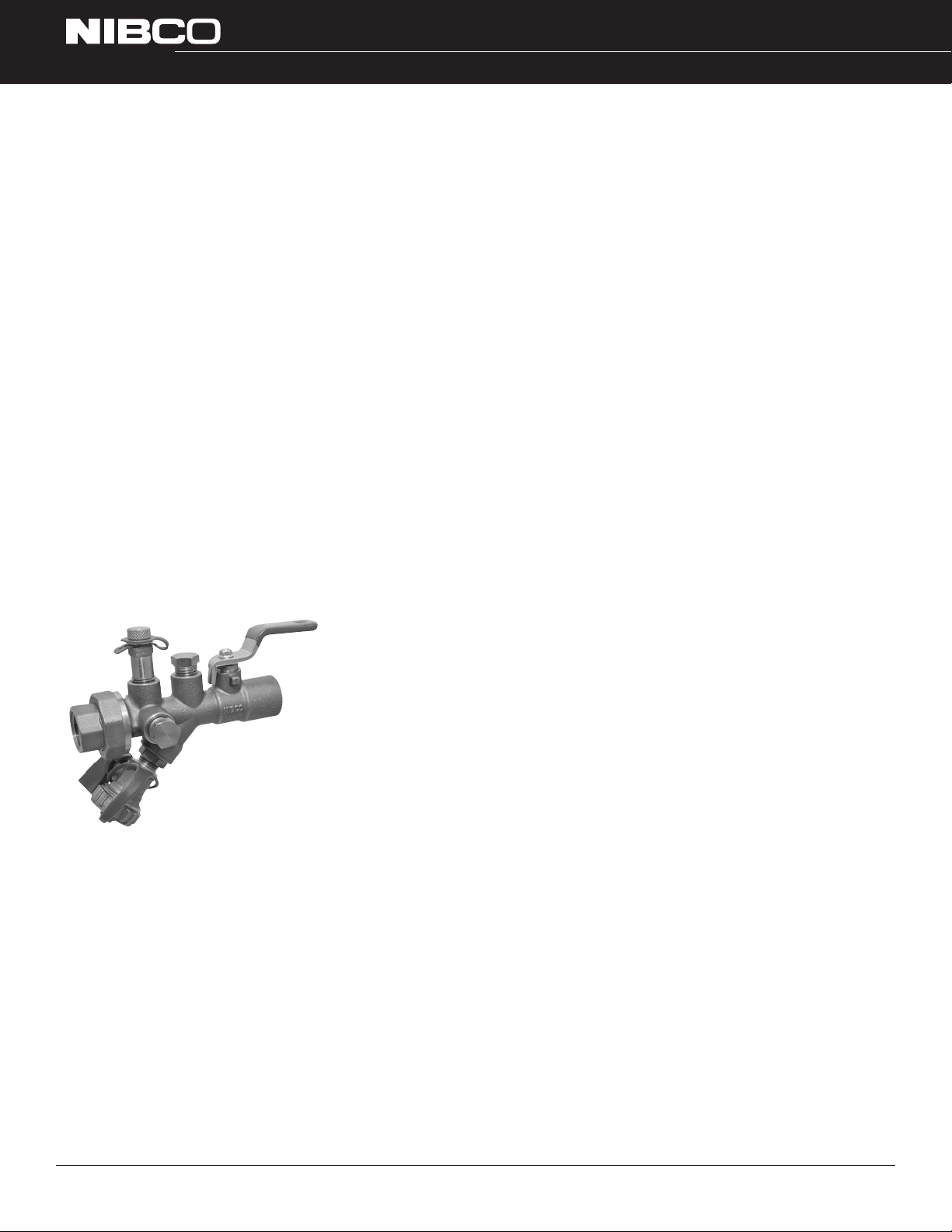
• Assemble and hand tighten all the sub-assemblies together using union connectors ensuring that the body o-ring is in
place and the orientation of the valves is with the drain valve vertically down and the valves with strainer and drain
have the strainer below the horizontal center line as shown.
• Using a correctly fitting wrench or spanner, further tighten the union nut ¼ turn. Excessive force is not required.
• Using the NIBCO® PRESS SYSTEM®TOOL using the correct sized jaws when making press joints.
• Fit the assembled kit to the coil and supply pipework.
Additional Technical Information
For additional technical information on installation see the individual IOMs supplied with the product or which are available
from NIBCO®.
Operation
This IOM is not intended as a guide to system balancing, which should be conducted by a specialist balancing engineer.
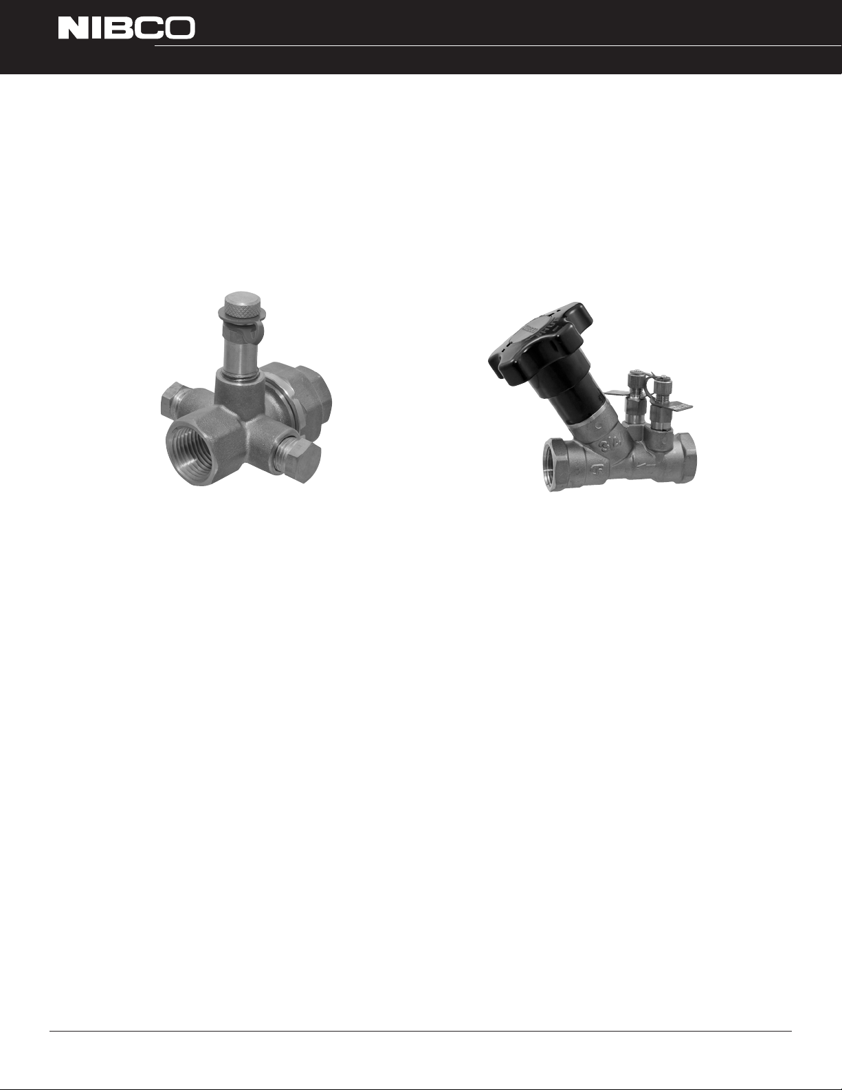
The operation of NIBCO®Coil-Connect®valves will be described along with additional functions.
The valves can be supplied with additional pressure test points and manual air vents to aid the balancing process.
The pressure loss through the coil (differential pressure ∆p) can be determined by using any pressure test points in the
supply and return branches.
The selection of the flow cartridges for the automatic balancing valve should have been made by the system designer, the
cartridge should be installed into the body after flushing but prior to system balancing.
Probe Insertion
For safety reasons, all manometer probe insertions of the P/T port must be carried out with the system cold.
Remove the screwed cap and insert the test probe into the P/T port. A silicone oil or grease should be lightly applied to the
shaft of the probe before insertion. No other type of lubricant should be used. Always refit the screwed cap.
Coil-Connect® Kits
Installation, Operation and Maintenance
5 of 10