1
www.climacoolcorp.com
Introduction
General Description
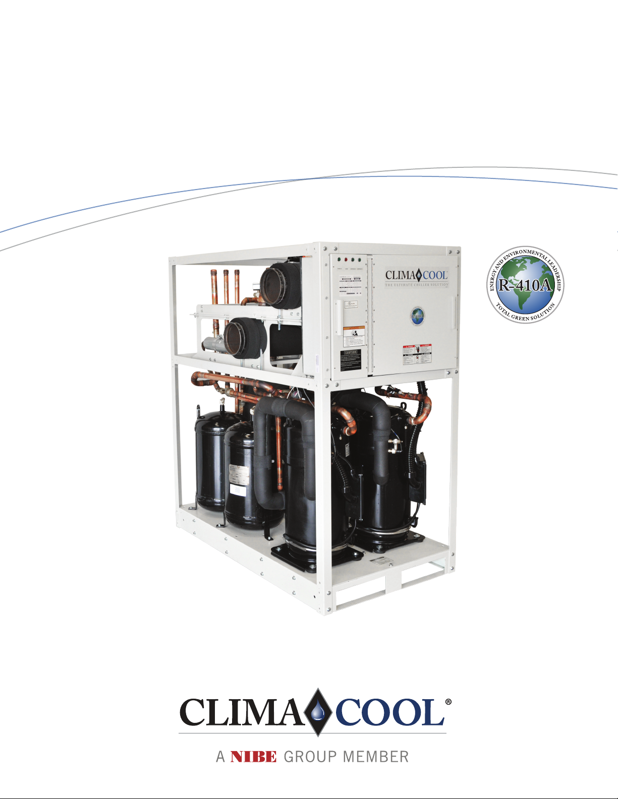
The ClimaCool®
cooled modular chiller is designed to provide the most
and serviceable modular chiller in the industry. The UCR
utilizes R-410A refrigerant.
Modules are available in 30, 50 and 70 tons, which when
capacity requirements from 30 to 400 tons per bank.
Safety
Throughout this manual, warning, danger, caution and
attention notices appear. Read these items carefully before
attempting any installation, service or troubleshooting
of the equipment. All labels on unit access panels must
be observed.
DANGER: Immediate hazardous situation which, if not avoided,
will result in death or serious injury.
WARNING: Potentially hazardous situation which, if not
avoided, could result in death or serious injury.
CAUTION: Potentially hazardous situation or an unsafe practice
which, if not avoided, could result in minor or moderate injury
or product or property damage.
ATTENTION: Notication of installed, operation or maintenance
information which is important, but not hazard related.
CAUTION/ATTENTION
installed wiring. Unit terminals are
not designed to accept other types of
conductors.
Utilisez uniquement des conducteurs en
cuivre pour le câblage. Bornes de l’unité
ne sont pas conçus pour accepter
d’autres types de conducteurs.
CAUTION/ATTENTION
3 PHASE SCROLL
COMPRESSOR UNIT
UNITÉ COMPRESSEUR
SCROLL 3-PHASE
If this unit uses a 3 Phase Scroll
Compressor, the following instructions
MUST BE followed:
• Unit power supply MUST BE wired
in the proper sequence to avoid
damage to the 3 Phase Scroll
Compressor;
• Scroll Compressors with
INCORRECT rotation show the
following characteristics:
- High sound level;
- High suction pressure and low
discharge pressure;
- Low current draw.
• If any of the three above
characteristsics exist, swap
two of the three supply wires
at the disconnect and recheck
compressor for incorrect rotation.
Si cet appareil utilise compresseur
scroll 3-Phase, les instructions
suivantes doivent être suivies:
• L’alimentation de l’appareil doit
être monté dans l’ordre correct
pour éviter endommager le
compresseur scroll 3-Phase;
• Compressuers scroll avec
rotation incorrecte montrent les
caractéristiques suivantes:
- Haut niveau de son;
- Pression d-aspiration élevée
et une faible pression de
décharge;
- Faible ampérage.
• Si l’un des trois éléments
mentionnés ci-dessus sont
remplies, échanger deux des trois
lignes électriques alimen tant la
la rotation du compresseur.
WARNING/ADVERTISSEMENT
To avoid possible injury or death
due to electrical shock, open the
power supply disconnect switch and
secure it in an open position during
installation.
Pour éviter les blessures ou la mort
par électrocution, ouvrir la interrupteur
ouverte lors de l’installation.
CAUTION/ATTENTION
Excessive Chlorine, undissolved
solids and other improper water
conditions WILL DAMAGE the
internal heat exchanger & WILL VOID
YOUR WARRANTY!
Chlore excessive, solides non dissous
et les autres impropre conditions de
l’eau ENDOMMAGERA l’échangeur
de chaleur interne et ANNULERA
VOTRE GARANTIE!
WARNING/ADVERTISSEMENT
WATER AND REFRIGERANT
SYSTEMSUNDERPRESSURE
EAU ET FRIGORIGÈNE
EQUIPEMENTS SOUS
PRESSION
• Isolate/Lockout source and relieve
pressure BEFORE servicing
equipment.
• Failure to relieve pressure may
result in property damage, serious
bodily injury or death!
• Isoler la source / de verrouillage
et de soulager la pression avant
entretien de l’équipement.
• Le défaut de soulager la pression
peut entraîner des dommages
matériels des blessures corporelles
graves ou la mort!
ATTENTION
To avoid the release of refrigerant into the atmosphere, the refrigerant circuit of
this unit must be serviced only by technicians who meet local, state and federal
All refrigerant discharged from this unit must be recovered WITHOUT
EXCEPTION. Technicians must follow industry accepted guidelines and all
local, state and federal statues for the recovery and disposal of refrigerants.
If a compressor is removed from the unit, system refrigerant circuit oil will
remain in the compressor. To avoid leakage of compressor oil, the refrigerant
lines of the compressor must be sealed after it is removed.
WARNING/ADVERTISSEMENT
Disconnect power supply(ies)
before servicing. Refer servicing
Electric shock hazard. May
result in injury or death!
Debrancher avant d’entreprendre
le dépannage de l’appareil.
pour le dépannage. Risque de
choc électrique. Résiltat de mai
dans dommages ou la mort!
CAUTION/ATTENTION
personnel only. Refrigerant
system under pressure. Relieve
pressure before using torch.
Recover refrigerant and store or
dispose of properly.
Conifer la maintenance à un
Décomprimer avant d’exposer
frigorigene et le stocker ou le
détrulre correctement.