3
We reserve the right to make technical changes 83050406cUK – Translation of the operating manual NIBETM AP-AW10
Contents
INFORMATION FOR OPERATORS AND
QUALIFIED SPECIALISTS
PLEASE READ FIRST..................................................................2
SYMBOLS .....................................................................................2
INTENDED USE..........................................................................4
EXCLUSION OF LIABILITY......................................................4
EC CONFORMITY .....................................................................4
SAFETY .........................................................................................4
CUSTOMER SERVICE ................................................................5
WARRANTY / GUARANTEE...................................................5
DISPOSAL ....................................................................................5
FUNCTIONING PRINCIPLE
OF HEAT PUMP SYSTEM ....................................................6
AREA OF UTILIZATION...........................................................6
HEAT QUANTITY RECORDING ............................................6
OPE R ATI ON ................................................................................6
CARE OF THE UNIT..................................................................7
MAINTENANCE OF THE UNIT...............................................7
Cleaning and rinsing of unit components..........................7
MALFUNCTIONS.......................................................................7
INSTRUCTIONS FOR
QUALIFIED TECHNICIANS
SCOPE OF DELIVERY ................................................................8
INSTALLATION ..........................................................................8
Installation location..............................................................8
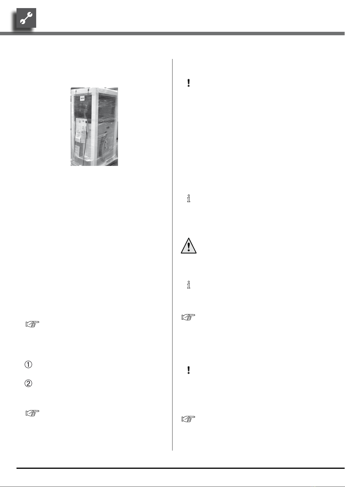
Transport to installation location......................................9
Installation............................................................................10
INSTALLATION OF THE
VENTILATION DUCT....................................................... 11
Converting from air blower on the right to air blower
on the left ......................................................................11
The air duct system 700 (accessory)...............................12
Product advantages.............................................................13
Wall duct(s) assembly.........................................................13
Air ducts assembly..............................................................14
Securing the air duct into the wall duct..........................15
Securing the air duct on the heat pump..........................15
Screen frame assembly.......................................................16
Wire mesh grille and weather/rain guards assembly ....16
INSTALLATION / CONNECTION TO HEATING CIRCUIT
17
Manometer...........................................................................18
Discharge hot water safety valve and condensate
discharge ........................................................................18
HOT-WAT ER TAN K .................................................................19
ELECTRICAL CONNECTIONS .............................................19
RINSING, FILLING AND BLEEDING THE SYSTEM ..........21
Water quality of the fill and additional water in hot
water heating systems .................................................21
INSULATING THE HYDRAULIC CONNECTIONS ..........25
OVERFLOW VALVE..................................................................25
Inspecting and setting up the overflow valve.................25
INSTALLATION OF THE CONTROL ELEMENT ...............26
INSTALLATION AND REMOVAL OF THE SCREEN.........27
COMMISSIONING ...................................................................28
Safety temperature limiter................................................29
DISMANTLING .........................................................................29
TECHNICAL DATA / SCOPE OF DELIVERY ........................30
PERFORMANCE CURVES
Heating capacity/COP / power consumption / Free
compression, heating circuit
AP-AW10-6C.......................................................................32
AP-AW10-8C.......................................................................33
AP-AW10-10C .....................................................................34
AP-AW10-12C .....................................................................35
DIMENSIONAL DRAWINGS .................................................36
INSTALLATION PLANS
Installation plan version 1 .................................................37
Installation plan version 2 .................................................38
Installation plan version 3 .................................................39
Installation plan version 4 ................................................ 40
Installation plan version 5 .................................................41
Installation plan version 6 .................................................42
TERMINAL DIAGRAM.............................................................43
CIRCUIT DIAGRAMS
AP-AW10-6C - AP-AW10-8C ......................................... 44
AP-AW10-10C – AP-AW10-12C ......................................47
APPENDIX
EC DECLARATION OF CONFORMITY..............................50