Nibe F2120 Series User guide

IHB EN 1817-4
331385
INSTALLER MANUAL
Air/water heat pump
NIBE F2120 8, 12, 16, 20


41 Important information
4Safety information
6Symbols
6Marking
6Serial number
6Recovery
6Environmental information
7Inspection of the installation
8
Compatible indoor modules (VVM) and control
modules (SMO)
8Indoor modules
8Control modules
92 Delivery and handling
9Transport and storage
9Assembly
10Compressor heater
10Condensation
13Installation area
13Supplied components
14Removing the side cover and top panel
153 The heat pump design
15General
19Distribution box
204 Pipe connections
20General
20Pipe coupling heating medium circuit
20Pressure drop, heating medium side
21Heat insulation
21Installing flex hoses
225 Electrical connections
22General
23Accessibility, electrical connection
24Configuration using DIP switch
25Connections
28Optional connections
32Connecting accessories
336 Commissioning and adjusting
33Preparations
33Balance temperature
33Filling and venting
34Start-up and inspection
34Readjusting, heating medium side
35Adjustment, charge flow
367 Control - Introduction
36General
36LED status
36Master control
37Control conditions
38Control - Heat pump EB101
398 Disturbances in comfort
39Troubleshooting
419 Alarm list
4310 Accessories
4411 Technical data
44Dimensions
45Sound pressure levels
46Technical specifications
49Working area
50Heating
52Cooling
53Energy labelling
58Electrical circuit diagram
67Item register
71Contact information
3Table of ContentsNIBE F2120
Table of Contents

Safety information
This manual describes installation and service proced-
ures for implementation by specialists.
The manual must be left with the customer.
This appliance can be used by children
aged from 8 years and above and persons
with reduced physical, sensory or mental
capabilities or lack of experience and
knowledge if they have been given super-
vision or instruction concerning use of the
appliance in a safe way and understand
the hazards involved. The product is inten-
ded for use by experts or trained users in
shops, hotels, light industry, farming and
similar environments.
Children must be instructed/supervised to
ensure that they do not play with the appli-
ance.
Do not allow children to clean or maintain
the appliance unsupervised.
This is an original manual. It may not be
translated without the approval of NIBE.
Rights to make any design or technical
modifications are reserved.
©NIBE 2018.
SAFETY PRECAUTIONS
Caution
Install the system in full accordance with this installation manual.
Incorrect installation can cause bursts, personal injury, water leaks,
refrigerant leaks, electric shocks and fire.
Pay attention to the measurement values before working on the
cooling system, especially when servicing in small rooms, so that
the limit for the refrigerant’s concentration is not exceeded.
Consult an expert to interpret the measurement values. If the refriger-
ant concentration exceeds the limit, there may be a shortage of oxygen
in the event of any leak, which can cause serious injury.
Use original accessories and the stated components for the in-
stallation.
If parts other than those stated by us are used, water leaks, electric
shocks, fire and personal injury may occur as the unit may not work
properly.
Ventilate the working area well – refrigerant leakage may occur
during service work.
If the refrigerant comes into contact with naked flames, poisonous
gas is created.
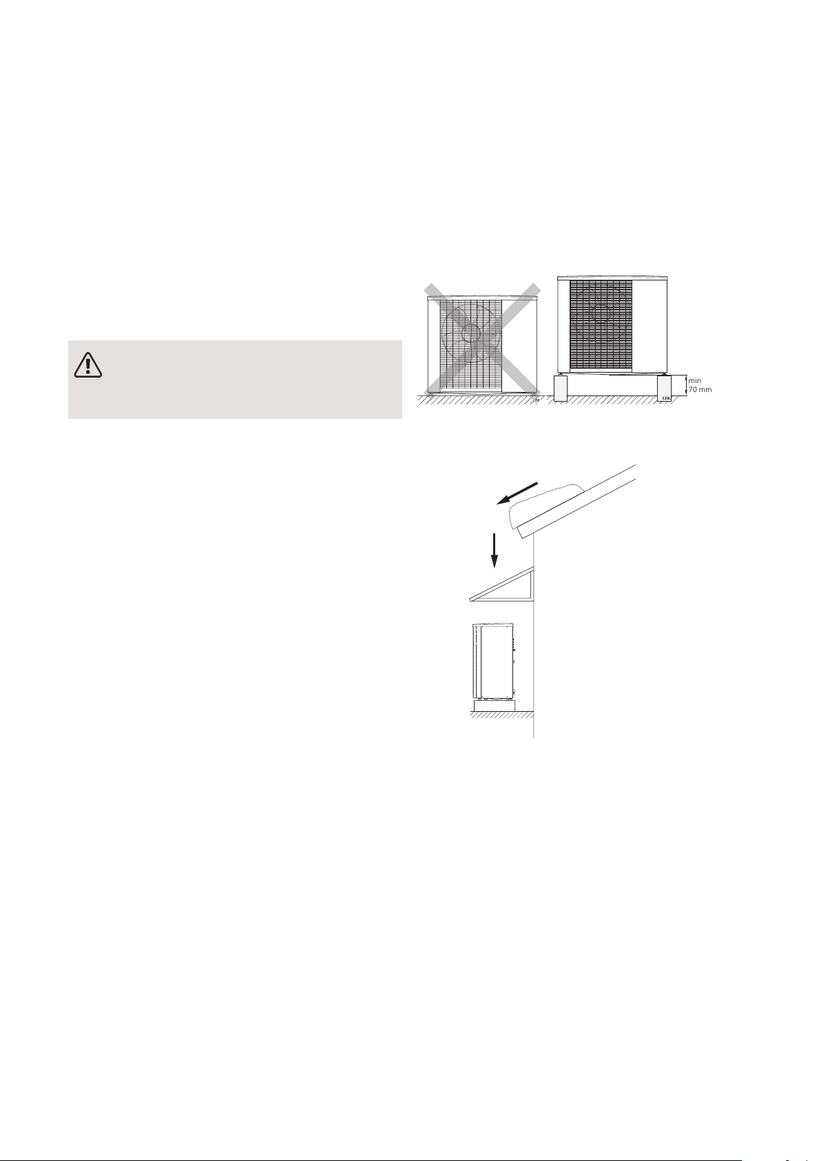
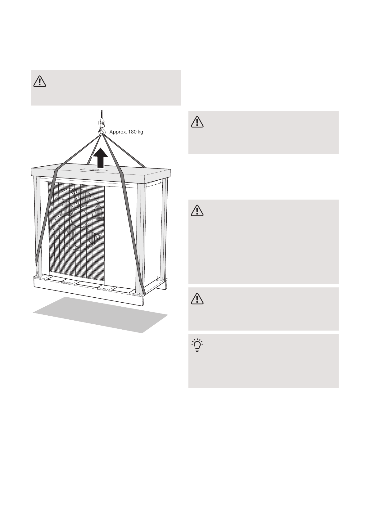
Install the unit in a location with good support.
Unsuitable installation locations can cause the unit to fall and cause
material damage and personal injury. Installation without sufficient
support can also cause vibrations and noise.
Ensure that the unit is stable when installed, so that it can with-
stand earthquakes and strong winds.
Unsuitable installation locations can cause the unit to fall and cause
material damage and personal injury.
The electrical installation must be carried out by a qualified
electrician and the system must be connected as a separate cir-
cuit.
Power supply with insufficient capacity and incorrect function can
cause electric shocks and fire.
Use the stated cables for the electrical connection, tighten the
cables securely in the terminal blocks and relieve the wiring cor-
rectly to prevent overloading the terminal blocks.
Loose connections or cable mountings can cause abnormal heat pro-
duction or fire.
Check, after completed installation or service, that no refrigerant
leaks from the system in gas form.
If refrigerant gas leaks into the house and comes into contact with an
aerotemp, an oven or other hot surface, poisonous gases are produced.
Switch off the compressor before opening/breaching the refriger-
ant circuit.
If the refrigerant circuit is breached /opened whilst the compressor
is running, air can enter the process circuit. This can cause unusually
high pressure in the process circuit, which can cause bursts and per-
sonal injury.
Switch off the power supply in the event of a service or inspec-
tion.
If the power supply is not shut off, there is a risk of electric shocks
and damage due to the rotating fan.
Do not run the unit with removed panels or protection.
Touching rotating equipment, hot surfaces or high voltage parts can
cause personal injury due to entrapment, burns or electric shocks.
Cut the power before starting electrical work.
Failure to cut the power can cause electric shocks, damage and incor-
rect function of the equipment.
Care
Carry out the electrical installation with care.
Do not connect the ground lead to the gas line, water line, lightning
conductor or telephone line's ground lead. Incorrect grounding can
cause unit faults such as electric shocks due to short-circuiting.
Use main switch with sufficient breaking capacity.
If the switch does not have sufficient breaking capacity, malfunctions
and fire can occur.
Always use a fuse with the correct rating in the locations where
fuses are to be used.
Connecting the unit with copper wire or other metal thread can cause
unit breakdown and fire.
Cables must be routed so that they are not damaged by metal
edges or trapped by panels.
Incorrect installation can cause electric shocks, heat generation and
fire.
NIBE F2120Chapter 1 | Important information4
1 Important information

Do not install the unit in close proximity to locations where
leakage of combustible gases can occur.
If leaking gases collect around the unit, fire may occur.
Do not install the unit where corrosive gas (for example nitrous
fumes) or combustible gas or steam (for example thinner and
petroleum gases) can build up or collect, or where volatile com-
bustible substances are handled.
Corrosive gas can cause corrosion to the heat exchanger, breaks in
plastic parts etc. and combustible gas or steam can cause fire.
Do not use the unit where water splashes may occur, for example
in laundries.
The indoor section is not waterproof and electric shocks and fire can
therefore occur.
Do not use the unit for specialist purposes such as for storing
food, cooling precision instruments, freeze-conservation of anim-
als, plants or art.
This can damage the items.
Do not install and use the system close to equipment that gener-
ates electromagnetic fields or high frequency harmonics.
Equipment such as inverters, standby sets, medical high frequency
equipment and telecommunications equipment can affect the unit
and cause malfunctions and breakdowns. The unit can also affect
medical equipment and telecommunications equipment, so that it
functions incorrectly or not at all.
Do not install the outdoor unit in the locations stated below.
- Locations where leakage of combustible gas can occur.
- Locations where carbon fibre, metal powder or other powder that
can enter the air.
- Locations where substances that can affect the unit, for example,
sulphide gas, chlorine, acid or alkaline substances can occur.
- Locations with direct exposure to oil mist or steam.
- Vehicles and ships.
- Locations where machines that generate high frequency harmonics
are used.
- Locations where cosmetic or special sprays are often used.
- Locations that can be subjected to direct salty atmospheres. In this
case, the outdoor unit must be protected against direct intakes of
salty air.
- Locations where large amounts of snow occur.
- Locations where the system is exposed to chimney smoke.
If the bottom frame of the outdoor section is corroded, or in any
other way damaged, due to long periods of operation, it must
not be used.
Using an old and damaged frame can cause the unit to fall and cause
personal injury.
If soldering near the unit, ensure that solder residue does not
damage the drip tray.
If solder residue enters the unit during soldering, small holes can ap-
pear in the tray resulting in water leakage. To prevent damage, keep
the indoor unit in its packing or cover it.
Do not allow the drainage pipe to exit into channels where pois-
onous gases, containing sulphides for example, can occur.
If the pipe exits into such a channel, any poisonous gases will flow
into the room and seriously affect the user's health and safety.
Insulate the unit's connection pipes so that the ambient air
moisture does not condense on them.
Insufficient insulation can cause condensation, which can lead to
moisture damage on the roof, floor, furniture and valuable personal
property.
Do not install the outdoor unit in a location where insects and
small animals can inhabit.
Insects and small animals can enter the electronic parts and cause
damage and fire. Instruct the user to keep the surrounding equipment
clean.
Take care when carrying the unit by hand.
If the unit weights more than 20 kg, it must be carried by two people.
Use gloves to minimize the risk of cuts.
Dispose of any packaging material correctly.
Any remaining packaging material can cause personal injury as it may
contain nails and wood.
Do not touch any buttons with wet hands.
This can cause electric shocks.
Do not touch any refrigerant pipes with your hands when the
system is in operation.
During operation the pipes become extremely hot or extremely cold,
depending on the method of operation. This can cause burn injuries
or frost injuries.
Do not shut off the power supply immediately after operation
has start.
Wait at least 5 minutes, otherwise there is a risk of water leakage or
breakdown.
Do not control the system with the main switch.
This can cause fire or water leakage. In addition, the fan can start un-
expectedly, which can cause personal injury.
5Chapter 1 | Important informationNIBE F2120

Symbols
NOTE
This symbol indicates danger to person or ma-
chine .
Caution
This symbol indicates important information
about what you should consider when installing
or servicing the installation.
TIP
This symbol indicates tips on how to facilitate
using the product.
Marking
The CE mark is obligatory for most products sold in
the EU, regardless of where they are made.
CE
Classification of enclosure of electro-technical equip-
ment.
IP24
Danger to person or machine.
!
Read the User Manual.
Serial number
The serial number can be found at the top left on the
rear cover and at the bottom on the side.
F2120
Serial number
Caution
You need the product's (14 digit) serial number
for servicing and support.
Recovery
Leave the disposal of the packaging to the in-
staller who installed the product or to special
waste stations.
Do not dispose of used products with normal
household waste. It must be disposed of at a
special waste station or dealer who provides this type
of service.
Improper disposal of the product by the user results in
administrative penalties in accordance with current le-
gislation.
Environmental
information
The equipment contains R410A, a fluorinated green-
house gas with a GWP value (Global Warming Potential)
of 2088. Do not release R410A into the atmosphere.
NIBE F2120Chapter 1 | Important information6

Inspection of the installation
Current regulations require the heating installation to be inspected before it is commissioned. The inspection must
be carried out by a suitably qualified person. Fill in the page for information about installation data in the User
manual.
DateSignatureNotesDescription
✔
Heating medium (page 20)
System flushed
System vented
Particle filter
Shut-off and drain valve
Charge flow set
Electricity (page 22)
Fuses property
Safety breaker
Earth circuit-breaker
Heating cable type/effect
Fuse size, heating cable (F3)
Communication cable connected
F2120 addressed (only when cascade
connection)
Connections
Main voltage
Phase voltage
Miscellaneous
Condensation water pipe
Insulation condensation water pipe,
thickness (if KVR 10 is not used)
NOTE
Check the connections, main voltage and phase voltage before the machine is started, to prevent damage
to the heat pump electronics.
7Chapter 1 | Important informationNIBE F2120

Compatible indoor modules (VVM) and control
modules (SMO)
SMO 40SMO 20VVM 500VVM 320VVM 310
XXXXXF2120-8
XXXXXF2120-12
XXXXXF2120-16
XXXXXF2120-20
Indoor modules
VVM 310VVM 310
With integrated EMK 310
Part no. 069 084
Part no. 069 430
VVM 320
Stainless steel, 3x230 V
Part no. 069 113
VVM 320
Stainless steel, 1x230 V
Part no. 069 111
VVM 320
Stainless steel, 3x400 V
Part no. 069 109
VVM 320
Enamel, 3x400 V
With integrated EMK 300
Part no. 069 110
VVM 500
Part no. 069 400
VVM 320
Copper, 3x400 V
Part no. 069 108
Control modules
SMO 20
Control module
Part no. 067 224
SMO 40
Control module
Part no. 067 225
NIBE F2120Chapter 1 | Important information8

Transport and storage
F2120 must be transported and stored vertically.
NOTE
Ensure that the heat pump cannot fall over
during transport.
Ensure that the heat pump cannot be damaged during
transportation.
Assembly
• Place F2120 outdoors on a solid level base that can
take the weight, preferably a concrete foundation. If
concrete slabs are used they must rest on asphalt or
shingle.
• The lower edge of the evaporator must be at the level
of the average local snow depth. The concrete
foundation or concrete plinths must therefore be at
least 70 mm high.
•F2120 should not be positioned next to noise sensitive
walls, for example, next to a bedroom.
• Also ensure that the placement does not inconveni-
ence the neighbours.
• F2120 must not be placed so that recirculation of the
outdoor air can occur. This causes lower output and
impaired efficiency.
• The evaporator must be sheltered from direct wind / ,
which negatively affects the defrosting function. Place
F2120 protected from wind / against the evaporator.
• Some water may drip from the drainage hole below
F2120. Make sure that water can run off by selecting
a suitable material underneath F2120 (see page 10).
• Care must be exercised so that the heat pump is not
scratched during installation.
LEK
F2120
min 300 mm
LEK
F2120
LEK
min
70 mm
Do not place F2120 directly on the lawn or other non
solid surface.
If there is a risk of snow slip from roof, a protective roof
or cover must be erected to protect the heat pump,
pipes and wiring.
9Chapter 2 | Delivery and handlingNIBE F2120
2 Delivery and handling

LIFT FROM THE STREET TO THE SET UP
LOCATION
If the base allows, the simplest thing is to use a pallet
truck to move the F2120 to the set up location.
NOTE
The centre of gravity is offset to one side (see
print on the packaging).
LEK
C:a 180 kg
Approx. 180 kg
If F2120 needs to be transported across soft ground,
such as a lawn, we recommend that a crane is used
that can lift the unit to the installation location. When
F2120 is lifted with a crane, the packaging must be un-
disturbed, see the illustration above.
If a crane vehicle cannot be used the F2120 can be
transported on an extended sack truck. F2120 must be
taken from its heaviest side and two people are required
to lift F2120.
LIFT FROM THE PALLET TO FINAL
POSITIONING
Before lifting remove the packaging and the securing
strap to the pallet.
Place lifting straps around each machine foot. Lifting
from the pallet to the base requires four persons, one
for each lifting strap.
SCRAPPING
When scrapping, the product is removed in reverse or-
der. Lift by the bottom panel instead of a pallet!
Compressor heater
F2120 is equipped with two compressor heaters that
heat the compressor before start-up and when the
compressor is cold.
NOTE
The compressor heater must have been active
for approx. 3 hours before the first start, see
section “Start-up and inspection” on page 34.
Condensation
The condensation water trough collects and leads away
most of the condensation water from the heat pump.
NOTE
It is important to the heat pump function that
condensation water is led away and that the
drain for the condensation water run off is not
positioned so that it can cause damage to the
house.
Condensation runoff should be checked regu-
larly, especially during the autumn. Clean if
necessary.
NOTE
The electrical installation and wiring must be
carried out under the supervision of an author-
ised electrician.
TIP
Pipe with heating cable for draining the con-
densation water trough is not included.
To ensure this function the accessory KVR 10
should be used.
• The condensation water (up to 50 litres/24 hrs) that
collects in the trough should be routed away by a pipe
to an appropriate drain, it is recommended that the
shortest outdoor stretch possible is used.
• The section of the pipe that can be affected by frost
must be heated by the heating cable to prevent
freezing.
• Route the pipe downward from F2120.
• The outlet of the condensation water pipe must be at
a depth that is frost free or alternatively indoors (with
reservation for local ordinances and regulations).
NIBE F2120Chapter 2 | Delivery and handling10

• Use a water trap for installations where air circulation
may occur in the condensation water pipe.
• The insulation must seal against the bottom of the
condensation water trough.
RECOMMENDED ALTERNATIVE FOR
LEADING OFF CONDENSATION WATER
Stone caisson
LEK
Frostfritt djup
F2120
Frost proof
depth
If the house has a cellar the stone caisson must be po-
sitioned so that condensation water does not affect the
house. Otherwise the stone caisson can be positioned
directly under the heat pump.
The outlet of the condensation water pipe must be at
frost free depth.
Drain indoors
Water seal
Joint
The condensation water is lead to an indoor drain (sub-
ject to local rules and regulations).
Route the pipe downward from F2120.
The condensation water pipe must have a water seal to
prevent air circulation in the pipe.
KVR 10 spliced as illustrated. Pipe routing inside house
not included.
Gutter drainage
LEK
F2120
Frostfritt
djup
Frost free
depth
Water seal
The outlet of the condensation water pipe must be at
frost free depth.
Route the pipe downward from F2120.
The condensation water pipe must have a water seal to
prevent air circulation in the pipe.
11Chapter 2 | Delivery and handlingNIBE F2120

Caution
If none of the recommended alternatives is
used good lead off of condensation water must
be assured.
NIBE F2120Chapter 2 | Delivery and handling12

Installation area The distance between F2120 and the house wall must
be at least 350 mm. The free space above F2120 must
be at least 1,000 mm. The free space in front must be
at least 1,000 mm for future servicing.
350 mm
Fritt utrymme bakom
Fritt utrymme framför
dock 1000 mm för ev. framtida service
Min. avstånd
vid användning
av flera F2300
600 mm
1000 mm
400 mm
Minimalt
fritt utrymme
600mm
Minimalt
fritt utrymme
Minimum free
space
However, free space in front must be
1000 mm for future servicing
Minimum free space
Minimum distance during use
of several F2120
600 mm
600 mm
At least 1000
mm
Free space behind
350 mm
400 mm
Supplied components
F2120-8, F2120-12
LEK
LEK
Filterball (G1").
2 x flexible pipes (DN25, G1")
with 4 x gaskets.
F2120-16, F2120-20
LEK
LEK
Filterball (G1 1/4").
2 x flexible pipes (DN25, G1
1/4") with 4 x gaskets.
13Chapter 2 | Delivery and handlingNIBE F2120

Removing the side cover and top panel
LEK
NIBE F2120Chapter 2 | Delivery and handling14

General
F2120 (1x230V)
LEK
GQ1
AA2
UB1
BT12
EP2
XL1
BT3
XL2
HS1
XL21
BT84
QN1
QN4
RM1
QN2
BP11
QN34
BT15
BT14 EB10
QA40 GQ10
BT17
RA1
BP9
BP1
BP2
BP8
XL20
BT81
HQ9
CA1
X6
15Chapter 3 | The heat pump designNIBE F2120
3 The heat pump design

F2120 (3x400V)
LEK
GQ1
AA2
UB1
BT12
EP2
XL1
BT3
XL2
HS1
XL21
BT84
QN1
QN4
RM1
QN2
BP11
QN34
BT15
BT14 EB10
QA40 GQ10
BT17
RF2RA1
BP9
BP1
BP2
BP8
XL20
BT81
HQ9
NIBE F2120Chapter 3 | The heat pump design16

LEK
Data
Serie.nr.
Art.nr.711453
OUT
IN
PF4
BT16
PF1
BT28
EP1
WM5
XL40
XL1
XL2
PF3
PF3
17Chapter 3 | The heat pump designNIBE F2120

Pipe connections
Connection, heating medium out of F2120XL1
Connection, heating medium in to F2120,XL2
Service connection, high pressureXL20
Service connection, low pressureXL21
Connection, drain condensation water troughXL40
Sensors etc.
High pressure pressostatBP1
Low pressure pressostatBP2
Low pressure transmitterBP8
High pressure sensorBP9
Pressure sensor, injectionBP11
Temperature sensor, returnBT3
Temperature sensor, condenser supply lineBT12
Temperature sensor, hot gasBT14
Temperature sensor, fluid pipeBT15
Temperature sensor, evaporatorBT16
Temperature sensor, suction gasBT17
Temperature sensor, ambientBT28
Temperature sensor, injection, EVI compressorBT81
Temperature sensor, suction gas evaporatorBT84
Electrical components
Base cardAA2
Capacitor (1x230V)CA1
Compressor heaterEB10
FanGQ1
InverterQA40
Harmonic filter (3x400V)RA1
Choke (1x230V)RA1
EMC filter (3x400V)RF2
Terminal block (1x230V)X6
Cooling components
EvaporatorEP1
CondenserEP2
CompressorGQ10
Particle filterHQ9
Drying filterHS1
Expansion valveQN1
Bypass valveQN4
4-way valveQN2
Expansion valve, subcoolingQN34
Non-return valveRM1
Miscellaneous
Type platePF1
Serial numberPF3
Sign, pipe connectionsPF4
Cable gland, incoming supplyUB1
Condensation water troughWM5
Designations in component locations according to standard IEC 81346-2.
NIBE F2120Chapter 3 | The heat pump design18

Distribution box
LEK
AA2 FC1
X24 F5 F4 X7 F2 F1
S2
S1
X23
X22
X21
X28 X27 F3 X2 X1 X5
X9
S3
Electrical components
Base cardAA2
Terminal block, incoming supplyX1
Terminal block, compressor supplyX2
Terminal block, external control voltageX5
Terminal block, 230V~X7
Terminal block, connection KVRX9
Terminal block, Compressor blocking,
Tariff
X21
Terminal block, communicationsX22
Terminal block, communicationsX23
Terminal block, fanX24
Terminal block, expansion valve QN1X27
Terminal block, subcooling QN34X28
Fuse, operating 230V~F1
Fuse, operating 230V~F2
Fuse for external heating cable KVRF3
Fuse, fanF4
Fuse, fanF5
Miniature circuit breaker (Replaced with automatic
protection (FB1) when installing accessory KVR 10.)
FC1
DIP switch, addressing heat pump during multi op-
eration
S1
DIP switch, different optionsS2
Reset buttonS3
Designations in component locations according to
standard IEC 81346-2.
19Chapter 3 | The heat pump designNIBE F2120

General
Pipe installation must be carried out in accordance with
current norms and directives.
F2120 can only operate up to a return temperature of
about 55 °C and an outgoing temperature of about 65 °C
from the heat pump.
F2120 is not equipped with external shut off valves on
the water side; these must be installed to facilitate any
future servicing. The return temperature is limited by
the return line sensor.
WATER VOLUMES
Depending on the size of F2120, an available water
volume is required to prevent short operating times and
to enable defrosting. For optimal operation of F2120, a
minimum available water volume of 10 litres times the
size number is recommended. E.g. F2120-12: 10 litres
x 12 = 120 litres.
NOTE
The pipe work must be flushed before the heat
pump is connected, so that any contaminants
do not damage the components.
Pipe coupling heating
medium circuit
• The heat pump must be vented by the upper connec-
tion (XL1) using the venting nipple on the enclosed
flexible hose.
• Install the enclosed particle filter before the inlet, i.e.
the lower connection (XL2) on F2120.
• All outdoor pipes must be thermally insulated with at
least 19 mm thick pipe insulation.
• Install shutoff and drain valves so that F2120 can be
emptied in the event of prolonged power failures.
• The supplied flexible hoses act as vibration dampers.
The flexible pipes are fitted so an elbow is created,
thus acting as vibration damping.
CHARGE PUMP
The charge pump (not included in the product) is
powered and controlled from the indoor module/control
module. It has a built-in anti-freezing function and must
therefore not be switched off when there is a risk of
freezing.
At temperatures below +2 °C the charge pump runs
periodically, to prevent the water from freezing in the
charge circuit. The function also protects against excess
temperatures in the charge circuit.
Pressure drop, heating
medium side
F2120-8, -12, -16, -20
0
1
2
3
4
5
6
7
8
9
10
11
12
13
14
15
00,05 0,1 0,15 0,2 0,25 0,3 0,35 0,4 0,45 0,5 0,55 0,6 0,65 0,7 0,75 0,8 0,85 0,9
Tryckfall
[kPa]
Flöde [l/s]
Tryckfall F2120
Pressure drop
(kPa)
Flow
(l/s)
-12/-16/-20
-8
NIBE F2120Chapter 4 | Pipe connections20
4 Pipe connections
Other manuals for F2120 Series
6
This manual suits for next models
9
Table of contents
Other Nibe Heat Pump manuals
Popular Heat Pump manuals by other brands

aquatherm
aquatherm AT800 installation manual

Carrier
Carrier 50JS Operating and maintaining guide

Trane
Trane Horizon OABE/F Series Installation, operation and maintenance

CIAT
CIAT YUNA II installation manual

Haier
Haier GE APPLIANCES Connect Series Service manual

alphainnoTec
alphainnoTec LW 140 operating manual