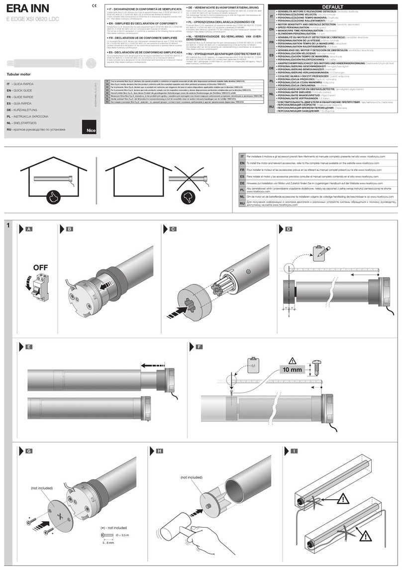
Note for reading this Manual – Some of the figures referred to in the text appear at the end of the manual.
GENERAL WARNINGS: SAFETY - INSTALLATION - USE (original instructions in Italian)
ATTENTION Important safety instructions. Follow all instructions as improper installation may cause serious damage
ATTENTION Important safety instructions. It is important for you to comply with these instructions for your own and other
people’s safety. Keep these instructions
•Before commencing the installation, check the “Technical characteristics” (in this manual), in particular whether this product is suitable for
automating your guided part. If it is not suitable, DO NOT continue with the installation
•The product cannot be used before it has been commissioned as specified in the chapter on “Testing and commissioning”
ATTENTION According to the most recent European legislation, the implementation of an automation system must comply
with the harmonised standards provided by the Machinery Directive in force, which enables declaration of the
presumed conformity of the automation. Taking this into account, all operations regarding connection to the
electricity grid, as well as product testing, commissioning and maintenance, must be performed exclusively by a
qualified and skilled technician!
•Before proceeding with the installation of the product, check that all the materials are in good working order and suited to the intended
applications
•This product is not intended to be used by persons (including children) whose physical, sensory or mental capacities are reduced, or who
lack the necessary experience or skill
•Children must not play with the appliance
•Do not allow children to play with the fixed control devices of the product. Keep the remote controls away from children
ATTENTION In order to avoid any danger from inadvertent resetting of the thermal cut-off device, this appliance must not be powered
through an external switching device, such as a timer, or connected to a supply that is regularly powered or switched off by
the circuit
•Provide a disconnection device (not supplied) in the plant’s power supply grid, with a contact opening distance permitting complete
disconnection under the conditions dictated by overvoltage category III
•Handle the product with care during installation, taking care to avoid crushing, denting or dropping it, or allowing contact with liquids of any
kind. Keep the product away from sources of heat and naked flames. Failure to observe the above can damage the product, and increase
the risk of danger or malfunction. Should this happen, stop installation immediately and contact Customer Service
•The manufacturer assumes no liability for damage to property, items or persons resulting from non-compliance with the assembly instructions.
In such cases the warranty for material defects is excluded
•The weighted sound pressure level of the emission A is lower than 70 dB(A)
•Cleaning and maintenance to be carried out by the user must not be carried out by unsupervised children
•Before working on the system (maintenance, cleaning), always disconnect the product from the mains power supply
•Check the system periodically, in particular all cables, springs and supports to detect possible imbalances, signs of wear or damage. Do not
use, if repairs or adjustments are necessary, since installation failure or an incorrectly balanced automation may cause injury
•The packing materials of the product must be disposed of in compliance with local regulations
•There must be at least 0.4 m between the driven parts and any fixed elements
•The wording on the tubular motors can be covered after assembly
•Motor with fixed power cable: the power cable cannot be replaced. If the cable is damaged, the appliance must be scrapped
•Motor with removable power cable and dedicated connector: if the power cable is damaged, it must be replaced by the manufacturer or
by the latter’s technical assistance service, or by a similarly qualified person, in order to prevent any type of risk.
•Be careful with moving shutters and keep away from them until they have lowered fully
•Be careful when activating the manual release device, as a raised shutter may rapidly drop in case of weak or broken springs
•Do not activate the awning when maintenance activities – such as window cleaning – are being carried out nearby
•Disconnect the awning from the power supply when maintenance activities such as window cleaning are being carried out nearby. Warning
for ‘shades with automatic control’
INSTALLATION WARNINGS
•Prior to installing the drive motor, remove any unnecessary cables and disable any appliance not required for motorised operation
•Install the manoeuvring assembly for manual release at a height below 1.8 m
NOTE: if removable, the manoeuvring assembly must be kept close to the door
•Make sure that the control devices are kept far from moving parts but nonetheless in a visible position.
The manoeuvring assembly of a switch kept manually closed must be located in a position visible from the guided part but far from moving
parts. It must be installed at a minimum height of 1.5 m
•The fixed control devices must be installed in a visible position
•For drive motors that allow for accessing unprotected moving parts once they have been installed, such parts must be installed 2.5 m above
the floor or other surface form which they can be accessed
1– English
