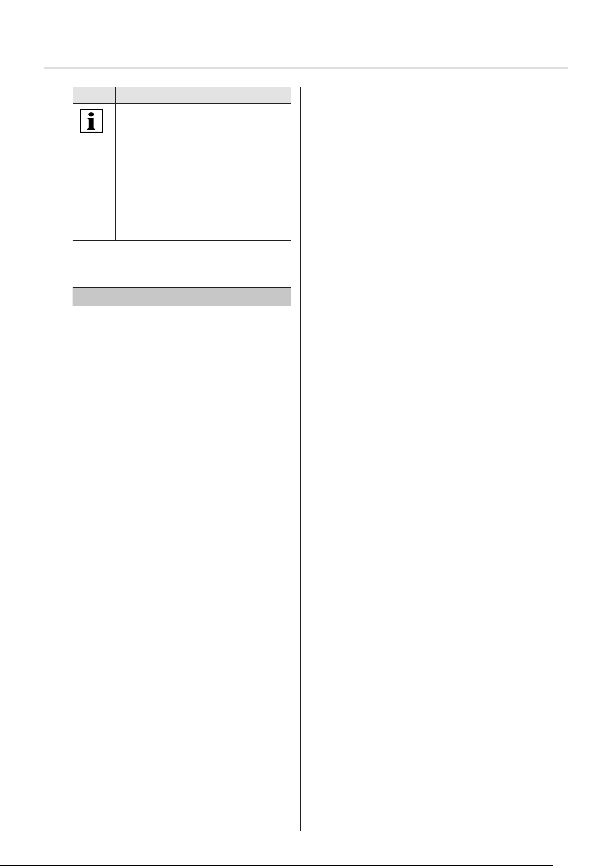
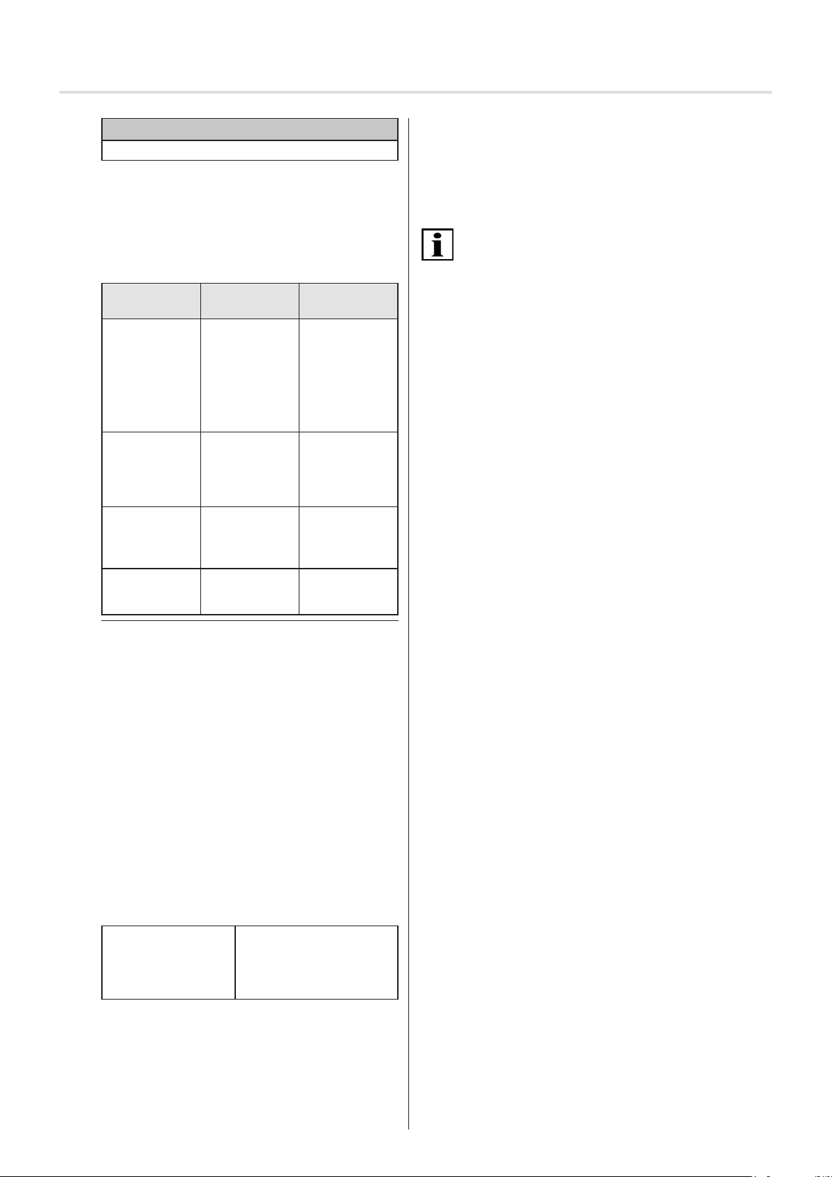
Symbol Signalwort Bedeutung
WICHTIG Dieses Symbol weist
auf wichtige Fakten und
Zustände sowie auf wei-
terführende Informationen
in dieser Betriebs- und
Montageanleitung hin.
Außerdem verweist es auf
bestimmte Anweisungen,
die zusätzliche Informa-
tionen geben oder Ihnen
helfen, einen Vorgang
einfacher durchzuführen.
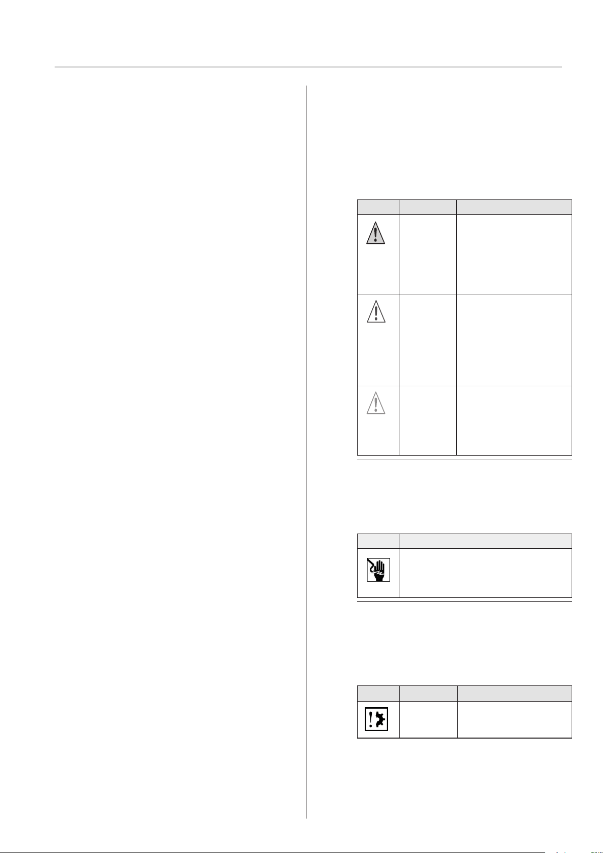
Fig. 3 Notation Sachschaden sowie Zusatzinformation
Das folgende Beispiel stellt den grundsätzlichen Aufbau
eines Sicherheitshinweises dar:
SIGNALWORT
Art und Quelle der Gefahr
Erläuterung zur Art und Quelle der Gefahr
►Maßnahmen zur Abwendung der Gefahr.
3.3 Sicherheitsgrundsätze
Das Produkt ist nach dem Stand der Technik und den
anerkannten sicherheitstechnischen Regeln gebaut und ist
betriebssicher. Bei der Ausführung des Produkts wurden
die grundlegenden Sicherheits- und Gesundheitsanforde-
rungen der zutreenden Gesetze, Normen und Richtlinien
angewandt. Die Sicherheit des Produkts wird durch die
EG-Konformitätserklärung bestätigt.
Alle Angaben zur Sicherheit beziehen sich auf die derzeit
gültigen Verordnungen der Europäischen Union. In anderen
Ländern muss vom Betreiber sichergestellt werden, dass
die zutreenden Gesetze und Landesverordnungen einge-
halten werden.
Neben den Sicherheitshinweisen in dieser Betriebsanlei-
tung müssen die allgemein gültigen Vorschriften zur Unfall-
verhütung und zum Umweltschutz beachtet und eingehalten
werden.
Das Produkt ist nur in technisch einwandfreiem Zustand
sowie bestimmungsgemäß, sicherheits- und gefahrenbe-
wusst unter Beachtung der Betriebsanleitung zu benutzen.
Das Produkt ist für den Einsatz laut Kapitel „Bestimmungs-
gemäße Verwendung“ konzipiert. Bei nicht bestimmungsge-
mäßer Verwendung können Gefahren für Leib und Leben
des Benutzers oder Dritter bzw. Beeinträchtigungen des
Produkts und anderer Sachwerte entstehen. Unfälle oder
Beinaheunfälle beim Gebrauch des Produkts, die zu Verlet-
zungen von Personen und/oder Schäden in der Arbeitsum-
gebung führten oder geführt hätten, müssen dem Hersteller
direkt und unverzüglich gemeldet werden.
Alle in der Betriebsanleitung und am Produkt aufgeführten
Sicherheitshinweise sind zu beachten. Ergänzend zu die-
sen Sicherheitshinweisen hat der Betreiber dafür zu sorgen,
dass alle im jeweiligen Einsatzland geltenden nationalen
und internationalen Regelwerke sowie weitere verbindliche
Regelungen zur betrieblichen Sicherheit, Unfallverhütung
und zum Umweltschutz eingehalten werden. Alle Arbeiten
am Produkt dürfen nur von geschultem, sicherheitstech-
nisch unterwiesenem und autorisiertem Personal durchge-
führt werden.
Die fachlich qualizierte Person muss alle im Installations-
land geltenden Normen und Gesetze befolgen und ihre
Kunden über die Bedienungs- und Wartungsbedingungen
des Produktes informieren.
3.4 Allgemeine Betreiberpichten
Der Betreiber ist verpichtet, das Produkt nur in ein-
wandfreiem und betriebssicherem Zustand einzusetzen.
Er muss dafür sorgen, dass neben den Sicherheitshin-
weisen in der Betriebsanleitung die allgemeingültigen
Sicherheits- und Unfallverhütungsvorschriften, die Vor-
gaben der DIN VDE 0100 sowie die Bestimmungen zum
Umweltschutz des jeweiligen Einsatzlandes beachtet und
eingehalten werden.
Der Betreiber ist dafür verantwortlich, dass alle Arbeiten
mit dem Produkt nur von geschultem, sicherheitstech-
nisch unterwiesenem und autorisierten Personal durch-
geführt werden.
Letztlich verantwortlich für den unfallfreien Betrieb ist
der Betreiber des Produkts oder das von ihm autorisierte
Personal.
Der Betreiber ist für die Einhaltung der technischen
Spezikationen, insbesondere für die Einhaltung der
statischen und dynamischen Lasten, verantwortlich.
Nichtbeachtung der statischen Lasten kann zum
Verlust der Stütz- bzw. Haltefunktion führen.
Im Sinne einer bestimmungsgemäßen Verwendung hat
der Betreiber umgebungsbezogen (gebäudeseitig) für ein
trockenes, nicht zu heißes Umfeld unter dem Einuss von
Strahlungswärme zu sorgen. Abweichungen sind mit dem
Hersteller abzustimmen.
3.5 Anforderungen an das Personal
Jede Person, die beauftragt ist, mit dem Produkt zu
arbeiten, muss die komplette Betriebsanleitung gelesen
und verstanden haben, bevor sie die entsprechenden
Arbeiten ausführt. Dies gilt auch, wenn die betreende
Person mit einem solchen Produkt bereits gearbeitet hat
oder dafür geschult wurde.
Vor Beginn aller Tätigkeiten muss das Personal mit den
Gefahren beim Umgang mit dem Produkt vertraut ge-
macht worden sein.
Jegliches Personal, welches beauftragt wurde, mit dem
Produkt zu arbeiten, darf keine körperlichen Einschrän-
kungen besitzen, die Aufmerksamkeit und Urteilsvermö-
gen zeitweilig oder auf Dauer einschränken (z.B. durch
Übermüdung).
Der Umgang mit dem Produkt sowie alle Montage-,
Demontage- und Reinigungsarbeiten durch Minderjährige
oder Personen, die unter Alkohol-, Drogen- oder Medika-
menteneinuss stehen, ist nicht gestattet.
Das Personal muss entsprechend der anfallenden Arbei-
ten und vorliegenden Arbeitsumgebungen geeigenete
persönliche Schutzausrüstung tragen.
Kindern nicht erlauben, mit ortsfesten Steuerungen zu
spielen; Fernsteuerungen von Kindern fernhalten.
Sich bewegende Rollladen beobachten und Personen
fernhalten, bis der Rollladen vollständig geschlossen ist.
3.6 Sicherheitshinweise zum technischen Zu-
stand
Das Produkt ist vor dem Einbau auf Beschädigungen und
ordnungsgemäßen Zustand zu prüfen.
Der Betreiber ist verpichtet, das Produkt nur in einwand-
freiem und betriebssicheren Zustand zu betreiben. Der
technische Zustand muss den gesetzlichen Anforderun-
gen entsprechen, die zum auf dem Typenschild genann-
ten Produktionsdatum Gültigkeit hatten.
© elero GmbH DE | 3
Sicherheit