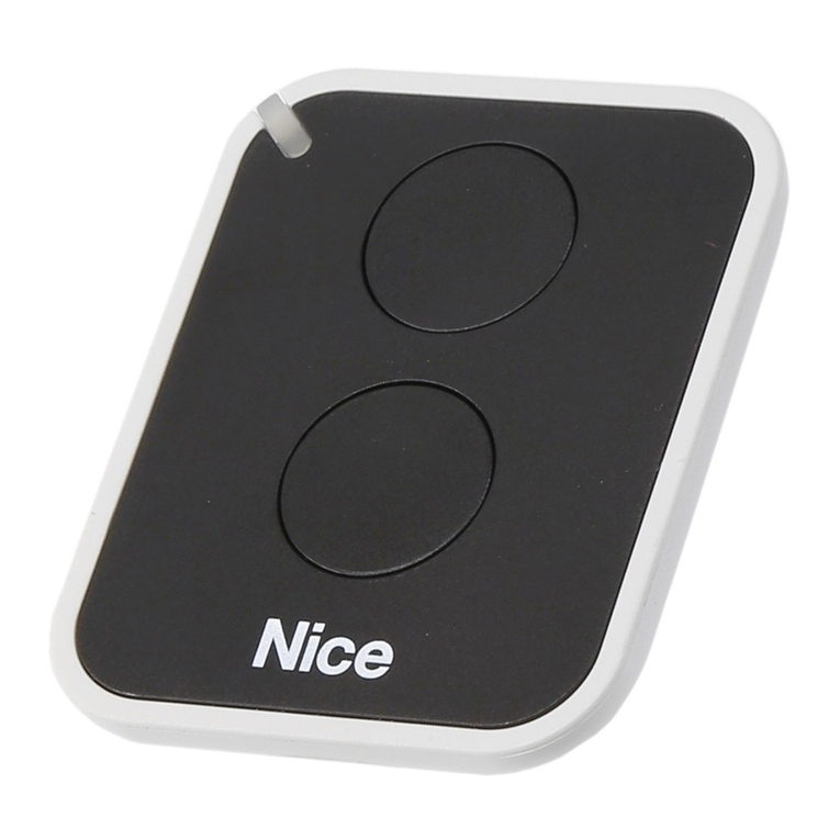
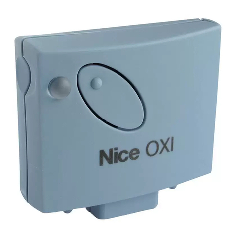
Nice NiceOne OX4 Product manual

EN -Installation and use instructions
and warnings
IT -Istruzioni ed avvertenze per
l’installazione e l’uso
FR -Instructions et avertissements
pour l’installation et l’utilisation
ES -Instrucciones y advertencias
para la instalación y el uso
DE -Anweisungen und Hinweise für
die Installation und die Bedienung
PL - Instrukcje i ostrzeżenia
związane z instalowaniem i
użytkowaniem
NL -Aanwijzingen en aanbevelingen
voor installering en gebruik
NiceOne
0682
Receiver
OX4 / OX4T


1
EN
ENGLISH
WARNINGS
WORKING IN SAFETY!
CAUTION! – For personal safety it is important to
observe these instructions.
CAUTION! – Warning - Important safety instructions:
keep these instructions in a safe place.
CAUTION! – All product installation, connection, pro-
gramming and maintenance operations must be per-
formed exclusively by a qualied and skilled technician.
Observe the following warnings:
– Never make any modications to part of the product
other than those specied in this manual. Unauthor-
ised operations can be the source of hazards and
malfunctions. The manufacturer declines all liability
for damage caused by makeshift modications to the
product.
– For cleaning the product surfaces, use a slightly damp (not
wet) cloth. Important –Never use substances containing
alcohol, benzene, diluents or other ammable substances.
Use of such substances could damage the product.
– Keep this manual in a safe place to enable future product
maintenance and programming operations.
– The product packaging material must be disposed of in full
observance of current local legislation governing waste dis-
posal.
This device complies with Part 15 of the FCC Rules and with
RSS-210 of Industry Canada. Operation is subject to the fol-
lowing two conditions: (1) this device may not cause harmful
interference, and (2) this device must accept any interference
received, including interference that may cause undesired
operation. Any changes or modications made to this device
without the express permission of the manufacturer may void
the user’s authority to operate this device.
1– PRODUCT DESCRIPTION AND
INTENDED USE
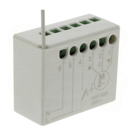
The OX4 / OX4T receiver is part of the NiceOpera System
produced by Nice. It is designed for use in systems for the
automation of gates, garage doors, road barriers, sun awn-
ings, shutters, skylights, and for the control of lights and elec-
trical circuits in general.
Any other use is to be considered improper and is strict-
ly prohibited! The manufacturer declines all liability for
damage resulting from improper use of the product and
other than as specied in this manual.
2– PRODUCT SPECIFICATIONS
–4 relays with normally open (NO) and normally closed (NC)
electrical contacts for use with electric power circuits.
–With 3 dip switches: 2 for Timer programming and 1 for
future use.

2
EN –14 functions for association with output relays.
–Memory capacity for storage of up to 1024 transmitters.
–Compatible with radio encoding “O-Code” / “FloR” /
“TTS”, or “Smilo”, or “Flo”.
(OX4T ONLY) – Integration of a transmitter enables re-
transmission of the received command to a second receiver
(“Repeater” function), thus expanding the operating range of
the receiver-transmitter system.
(OX4T ONLY) – Possibility of connection via radio to the
Obox programming unit by means of the built-in transmitter,
or via cable to the Oview programming unit. These devices
facilitate programming, management of memorised codes,
diagnostics and other operations.
(OX4T ONLY) – Assigned personal ID number, known as
“Certicate”, as stated on the sealed card supplied in the
pack. The certicate enables access to many operations
such as memorisation of new transmitters without the need
for direct intervention on the receiver. Caution! – Keep the
certicate in a safe place to prevent use by unauthorised
persons and “wireless” access to data stored in the receiver,
unless the latter has additional protection such as a pro-
grammed security password.
What is “NiceOpera”?
Nice Opera is a system comprising various
devices normally used in systems for the auto-
mation of gates, garage doors, and road barriers
with mobile arms, designed to communicate and
exchange data via radio, via “O-Code” encoding,
and via cable by means of the protocol “BusT4”,
with full integration of the two systems.
The devices in “NiceOpera” are:
• transmitters in the NiceOne series;
• receivers in the NiceOne series;
• gearmotors with “BusT4” type control unit.
There are also other supplementary software and
hardware devices in addition to the above:
• O-Box programming unit with dedicated
soft ware, for transmitters and receivers;
• Oview programming unit, for control units
and receivers. Oview can also be used in
conjunction with:
– a Bluetooth®module and dedicated soft-
ware, for data communication between
Oview and a Personal computer (or palm-

3
EN
top);
– a GSM®module and dedicated soft-
ware, for data communication via Internet
between Oview and a Personal computer
(or palmtop).
The Gsm®module also enables the use of
a smartphone and standard mobile phone:
these can be used to send a command to
an automation by means of a call or text
message; also, the smartphone, equipped
with the Windows®Mobile operating sys-
tem enables use of the software “Oview
software suite”.
3– PRODUCT INSTALLATION
01. Remove the top cover of the receiver (g. 1).
02. In the zones marked accordingly, drill the holes used to
route the cables and for wall-mounting of the receiver.
Caution! – Take suitable precautions to guarantee
the IP protection rating required for the type of
in stallation. In particular, t cable clamps (not sup-
plied) to guarantee protection of the power cables
and control cables against possible traction or tor-
sion.
03. Fix the receiver housing to the wall (g. 2). Caution! –
The receiver must be positioned so that the cables
enter the housing exclusively from the bottom.
4– ELECTRICAL CONNECTIONS
Fig. 3 shows the terminals and sockets used for connections:
– (A) for electrical power mains connection;
– (B) for aerial connection;
– (C and D) for connection of the contacts of the 4 relays;
– (E) for Obox connection;
– (F) for connection of Oview and the “BusT4” cable.
Each relay is tted with 1 common contact (C), 1 normally
open (NO) contact in standby status and 1 normally closed
(NC) contact in standby status: these are all voltage-free con-
tacts.
The contacts of the 4 relays have double insulation with
respect to the receiver circuit, as well as between the pair of
relays 1 and 2 and the pair of relays 3 and 4.
The double insulation enables the optional use of the contacts
in very low voltage circuits or mains voltage circuits with the
following options:

4
EN – use of all contacts in mains voltage electric circuits;
– use of all contacts in very low voltage electric circuits;
– use of relays 1and 2(or 3and 4) in mains voltage electric
circuits and relays 3and 4(or 1and 2) in very low voltage
electric circuits.
Relay wiring diagrams
Fig. 4 shows the diagram for connection of the relays to a
general electric circuit (motor, lamp etc.) with power from the
mains.
Fig. 5 shows the diagram for connection of the relays to a bi-
directional motor (awnings, Venetian blinds etc.).
Warnings for aerial connection
• When connecting the aerial supplied, leave the wire at the
length supplied and lay straight to avoid excessive bending.
• If the receiver is not in a good position and the radio signal
is weak, replace the aerial supplied with an external version
to improve reception (mod. ABF or ABFKIT). The new aerial
must be positioned as high as possible above any metal or
reinforced concrete structures present in the area.
21

5
EN
AGH
CDB
1234F
L
E
M
3
M
L
230 V
N
CH1
LN
NA
FUSE
CNC
C
NA C NC NA C NC NA C NC
CH2 CH3 CH4
5
L
230 V
N
CH1
LN
NA
FUSE
CNC NA C NC NA C NC NA C NC
CH2 CH3 CH4
4
110 - 230V AC 50/60Hz

6
EN 5– PROGRAMMING
Warnings:
Some programming functions in this chapter use the key P1
and led L1 (g. 3-G/H) of the receiver.
During programming the led emits a specic number of ash-
es, with a specic duration and colour (green, red or orange)
to indicate the current operating status. For the meaning of
these signals, consult Table B at the end of the manual.
Other functions can be programmed exclusively using the
devices Obox or Oview belonging to the NiceOpera system.
5.1 - MEMORISATION OF TRANSMITTERS
The receiver can memorise up to 1024 transmitters. Com-
patible with radio encoding “O-Code” / “FloR” / “TTS”, or
“Smilo”, or “Flo”.
Caution! – these three encoding groups are not compatible
with one another; therefore the rst transmitter memorised in
the transmitter also denes the encoding family for all the sub-
sequent transmitters.
To verify whether transmitters are already memorised on the
receiver and the relative encoding group, disconnect the
receiver from the power supply, switch on again and count the
number of green ashes, emitted by led L1:
1 ash = Flo encoding
2 ashes = O-Code / FloR / TTS encoding
3 ashes = Smilo encoding
5 ashes = no transmitter memorised
The transmitters can be memorised using one of the following
procedures:
• Procedure Mode I: programs all keys(*) of the transmitter
once only, associating each key to a relay, according to the
following scheme: key 1= relay 1/ key 2 = relay 2/ key 3=
relay 3/ key 4= relay 4.
“Mode I” programs each key to operate in “hold-to-run” mode
on the respective relay.
(*)Note – If the transmitter has several codes, – such as the
models ON9, WM009C etc. with the keyboard divided into
groups of keys with each group associated with a specic
code, as if these were separate transmitters – the “Mode I”
procedure only memorises the keys belonging to a specic
group; the procedure must be repeated for each group.
• Procedure Mode II: programs a single key of the trans-
mitter associating it with the required function, from those pre-
sent in Table A.
Memorising a
transmitter in “Mode I”
01. Press and hold P1 on the receiver until the green Led L1
illuminates (after approx. 4 seconds) and then release;
02. Within 10 seconds, press and hold any transmitter key
to be memorised, until the green led L1 on the receiver
emits the rst of 3 ashes to conrm memorisation.
When these ashes are completed, to memorise anoth-
er transmitter in “Mode I”, press any key on the new
transmitter within 10 seconds.
Memorising a
transmitter in “Mode II”
01. In Table A select the function to be programmed (e.g.
“Function 8”);
02. On the receiver, press P1 the same number of times

7
EN
as the number identifying the selected function (in our
example, 8 times). On completion, the green Led L1
emits the number of short ashes, equal to the number
of presses on the key (in our example, 8 short ashes);
03. Within 10 seconds, press and hold any transmitter key
to be memorised, until the green led L1 on the receiver
emits the rst of 3 ashes to conrm memorisation.
When these ashes are completed, to memorise a new
key with the same function (also on another transmitter)
press this new key within 10 seconds.
Table A – Association of functions with a transmitter
key
Function 1: activates relay 1 in hold-to-run mode;
Function 2: activates relay 2 in hold-to-run mode;
Function 3: activates relay 3 in hold-to-run mode;
Function 4: activates relay 4 in hold-to-run mode;
Function 5: activates relay 1 in On/Off mode;
Function 6: activates relay 2 in On/Off mode;
Function 7: activates relay 3 in On/Off mode;
Function 8: activates relay 4 in On/Off mode;
Function 9 (note 1): activates relay 1 and 2for bi-direc-
tional motor control (shutters or sun awnings)
Function 10 (note 1): activates relay 3 and 4for bi-direc-
tional motor control (shutters or sun awnings)
Function 11 (note 2): activates relay 1 for time interval set
in “Timer 1”
Function 12 (note 2): activates relay 3 for time interval set
in “Timer 2”
Function 13 (note 1): activates relay 1 and 2for bi-direc-
tional motor control (Venetian blinds)
Function 14 (note 1): activates relay 3 and 4for bi-direc-
tional motor control (Venetian blinds)
Note 1 (Functions 9, 10, 13, 14)
To memorise this function, press any key on the transmitter.
In this way the receiver memorises transmitter keys 1, 2, 3,
(4) simultaneously, conguring them with the following com-
mands: Key 1 = UP / Key 2 = STOP / Key 3 = DOWN / (Key
4= STOP).
To control a motor in both directions, the relays must be con-
nected as shown in g. 5.
• For Function 9 and 10: using the receiver, each time a
command is sent the relays are activated for the interval set
on the timer: Timer 1 for relays 1 and 2; Timer 2 for relays 3
and 4 (to program the timers, see chapter 5.3).
• For Function 13 and 14: using the receiver, each time a
command is sent, the relays remain active while the hold-
to-run key is pressed. However, if the command lasts for
more than 3 seconds, the relays remain active for the time
set on the timer: Timer 1 for relays 1 and 2; Timer 2 for
relays 3 and 4 (to program the timers, see chapter 5.3).
Note 2 (Functions 11, 12)
Using the receiver, each time a command is sent the relays
are activated for the interval set on the corresponding timer (to
program the timers, see chapter 5.3). Before the time elapses,
simply send a new command to restart the timer. On the other
8
EN 5.2 - MEMORISING A NEW TRANSMITTER
USING THE PROCEDURE “IN THE VICIN-
ITY OF THE RECEIVER”
[requires a transmitter already memorised]
A NEW transmitter can be memorised in the receiver memory
without acting directly on key of the receiver, but by simply
working within its reception range. To use this procedure,
an OLD transmitter, previously memorised (in “Mode I” or in
“Mode II”) and operative, is required. The procedure enables
the NEW transmitter to be memorised with the same settings
as the OLD version. Note – If using NiceOne transmitters as
alternative in this procedure, memorisation may be performed
using the “Enable Code” (refer to transmitter instruction man-
ual).
Procedure warnings
• The procedure must be performed within the recep-
tion range of the receiver (maximum 10-20 m from
receiver).
• If the OLD transmitter is memorised in “Mode I” dur-
ing the procedure press any key either on the Old or
New transmitter; on the other hand, if the OLD trans-
mitter is memorised in “Mode II”, during the proce-
dure press the required command key on the OLD
transmitter and the associated key to be memorised
for this command on the New transmitter.
• There are two procedures: choose one as preferred.
Standard procedure
01. On the NEW transmitter, press and hold the key *** for at
least 5 seconds and then release.
02. On the OLD transmitter, press the key *** 3 times and
then release.
hand, to interrupt the timer before the interval elapses, send a
new command, pressing the key for at least 3 seconds.
When using the receiver, if a relay receives several commands
consecutively – for example from two keys memorised on the
same relay but with different functions – the receiver executes
the last command sent in chronological order.

9
EN
03. On the NEW transmitter, press the same key pressed in
point 01 once and then release.
Alternative procedure
01. On the NEW transmitter, press and hold the key *** for at
least 3 seconds and then release.
02. On the OLD transmitter, press and hold the key *** for at
least 3 seconds and then release.
03. On the NEW transmitter, press the same key pressed in
point 01 for at least 3 seconds and then release.
04. On the OLD transmitter, press the same key pressed in
point 02 for at least 3 seconds.
5.3 - PROGRAMMING A TIMER
“Timer 1” and “Timer 2” represent the time in which the relays
remain active:
– Timer 1 used for relay 1. This timer corresponds to the work
time of relays 1 and 2, when programmed with Function 9,
11 or 13.
– Timer 2 used for relay 3. This timer corresponds to the work
time of relays 3 and 4, when programmed with Function 10,
12 or 14.
The factory settings of the two Timers is 120 seconds. This
value can be modied by means of the following “self-learn-
ing” procedure.
01. If the relay is active, deactivate with the relative command;
02. set dip switch 1 to ON (g. 3-L) to program Timer 1 or
dip switch 2 (g. 3-M) for Timer 2: the led next to the dip
switch illuminates to indicate activation of the program-
ming phase;
03. according to the selected timer, activate the required
relay by means of the relative key: the time count is
then started immediately;
04. when the required time has elapsed, press the key again
to deactivate the relay. The time elapsed has been mem-
orised and will be applied as the new timer value;
05. return the dip switch to OFF: the led next to the dip
switch turns off and the receiver returns to normal operat-
ing status.
5.4 - DELETING THE MEMORY
• Total memory deletion
To delete the entire memory of the receiver, or alternatively
only the memorised transmitters, proceed as follows:
01. Press and hold the receiver key and check the sequence
of the green Led status:
after approx. 4 seconds, the led illuminates
after approx. 4 seconds, the led turns off
after approx. 4 seconds, the led starts ashing…
02. Then:
– to delete all memorised transmitters, release the receiv-
er key on precisely the third ash of the led;
– to delete the entire memory (including transmitter
congurations and encoding family) release the key on
preci sely the fth ash of the led.
This function can be performed also using the programming
unit Obox or Oview.
• Deleting a single transmitter from the memory
To delete a single transmitter from the receiver memory, pro-
ceed as follows:

10
EN 01. Press and hold the receiver key
02. After the green led illuminates, on the transmitter to be
deleted from the memory, press and hold a key (*) until
the led on the receiver emits 5 quick green flashes
(=deletion conrmed). Then release the two keys.
(*)Note – If the transmitter is memorised in “Mode I” press
any key; if the transmitter is memorised in “Mode II” the entire
procedure must be repeated for each memorised key to be
deleted.
This function can be performed also using the programming
unit Obox or Oview.
6– ADVANCED PROGRAMMING
WARNING – Some settings described in this chap-
ter may only be possible if the receiver is combined
with other devices in the NiceOpera System; they also
require use of the programming unit Obox or Oview.
The receiver has other functions not described in this
manual that enable an increase in performance, secu-
rity level and ease of automation use. For further infor-
mation on the functions available, refer to the general
manual “NiceOpera System Book” or the instruction
manual of Obox or Oview.
• SETTING THE PASSWORD ON THE RECEIVER
[with Obox (OX4T ONLY) and Oview]
This function protects all programmed functions on the receiv-
er and also deactivates the key and led function. The function
is enabled by entering a password in the receiver, as selected
by the installer (maximum 10 digits).
When the function is active, the password must be entered
before programming or performing maintenance on the
receiver.
• ENABLING (or disabling) THE RECEIVER FOR
TRANSMITTER MEMORISATION
[with Obox (OX4T ONLY)]
This function is used to enable/disable the option on the
receiver for memorisation of a transmitter by means of the
procedure “in the vicinity of the receiver” (chapter 5, para-
graph 5.2) and/or by means of the “enable code” procedure
present on transmitters in the NiceOne series.
This function is useful to prevent events such as the accidental

11
EN
memorisation of transmitters not belonging to the system. To
enable/disable this function, proceed as follows:
01. Press and hold P1 to power up the receiver and wait for
Led L1 to emit rst the signals as specied in chapter
5.1; then ensure that it emits 2 quick orange ashes (=
procedure activated) and lastly that it indicates the colour
corresponding to the current enable status. Then release
the key.
02. Within 5 seconds, repeatedly press the receiver key to
select one of the following functions:
• Led OFF = No lock enabled
• Led GREEN = Memorisation “in the vicinity” locked
• Led RED = Memorisation with “enable code” locked
• Led ORANGE = Both memorisation modes locked (“in
the vicinity” and with “enable code”)
03. Within 5 seconds, press any key of a transmitter already
memorised on the receiver to save the selected function.
• ENABLING (or disabling) THE RECEIVER FOR
MEMORISATION OF A TRANSMITTER USING
THE RECEIVER “CERTIFICATE NUMBER”
[with Obox (OX4T ONLY)]
This function is used to enable/disable the option on the
receiver for memorising a transmitter by means of the receiver
cer ticate number.
For further information on the use of the certicate, refer to
the instruction manual of the transmitter and the NiceOpera
System Book.
• ENABLING (or disabling) UPDATES TO THE
TRANSMITTER PRIORITY STATUS
[with Obox (OX4T ONLY)]
This function is used to enable/disable the option on the
receiver for updating the priority level of the previously
memorised transmitter in the NiceOne series to a higher level.
This function is enabled by default. For further information on
managing priority, refer to the instruction manual of Obox and
the NiceOpera System Book.
• ENABLING (or disabling) RECEPTION OF NON-
ORIGINAL TRANSMITTER “IDENTITY CODES”
[with Obox (OX4T ONLY)]
This function is used to enable/disable the option on the
receiver to accept the command received from a transmitter
with an identity code that has been modied with respect to
the original factory setting. This function is enabled by default.
For further information on modifying transmitter identity codes,
refer to the instruction manual of Obox.
• ENABLING (or disabling) MANAGEMENT OF
ROLLING CODE (RND)
[with Obox (OX4T ONLY) and Oview]
This function is used to enable/disable the receiver for man-
agement of the variable section (rolling code) of an identity
code sent by a transmitter. When this function is active, the
receiver treats a “rolling code” as if it were a “xed” code, igno-
ring the variable section This function is disabled by default.

12
EN • ENABLING (or disabling) THE “REPEATER”
FUNCTION
[with Obox (OX4T ONLY)]
This function is used to enable/disable the option on the
receiver for repetition via radio of the command receiver, rout-
ing it to a second receiver. Using two receivers, one of which
with the “Repeater” function enabled, an automation can be
controlled from a greater distance to that normally covered by
a normal receiver-transmitter system.
This function is only available if receivers are associated with
transmitters using the “O-code” encoding system.
This function is disabled by default. To obtain this function,
it must be enabled on both the “repeater” receiver and the
required transmitters.
• ENABLING (or disabling) MANAGEMENT OF
TRANSMITTER KEY RELEASE
[with Obox (OX4T ONLY)]
This function is used to enable/disable the option on the
receiver synchronise the release of a key on a transmitter with
“O-Code” encoding and the response of an automation to
this action. Normally, when a command is sent, the manoeu-
vre is not stopped immediately on release of the key but after
a very brief interval (pre-set). Activation of this function enables
instant response of the automation on release of the key. This
function is disabled by default.
• ENABLING (or disabling) COMMAND DELIV-
ERY ON THE “T4 BUS” NETWORK
[with Oview]
This function is used to enable/disable the option on the
receiver for receiving and/or sending radio codes via the
BusT4 cable. On systems using this type of connection, if the
automation needs to be controlled at a distance greater than
that normally covered by the receiver-transmitter system, this
function can be enabled on receivers (at least 2) to increase
the radio transmission range; in this case the rst receiver
receives the command “via radio” and re-transmits it via the
Bus cable to the destination receiver (which has memorised
the code of the transmitter that has sent the command). This
function is disabled by default.
• EXECUTING A COMMAND SENT FROM
TRANSMITTERS IN THE SAME FAMILY
[with Obox (OX4T ONLY)]
To program transmitters with Obox, each transmitter can be
inserted in one or more “families” (up to 4 groups).
When the receiver receives a command, it first checks to
which the transmitter it belongs; if its family is enabled at that
time, the receiver controls the outputs otherwise the com-
mand is blocked and indicated by means of an orange ash
of the led.
The family groups are formed using Obox, while use of the
groups is managed by other devices such as Oview. In par-
ticular, this can enable/disable operation of group of transmit-
ters within specic set time bands.

13
EN
DISPOSAL OF THE PRODUCT
This product constitutes an integral part of the auto-
mation system, therefore it must be disposed of along
with it.
As in installation, also at the end of product lifetime, the dis-
assembly and scrapping operations must be performed by
qualied personnel.
This product is made up of different types of material, some of
which can be recycled while others must be disposed of. Seek
information on the recycling and disposal systems envisaged
by the local regulations in your area for this product category.
Caution! – some parts of the product may contain pollutant
or hazardous substances which, if disposed of into the envi-
ronment, may cause serious damage to the environment or
physical health.
As indicated by the symbol on the left,
disposal of this product in domestic
waste is strictly prohibited. Separate
the waste into categories for disposal,
according to the methods envisaged
by current legislation in your area, or
return the product to the retailer when
purchasing a new version.
Caution! – Local legislation may envisage serious nes in the
event of abusive disposal of this product.

14
EN Table B
SIGNALS EMITTED BY THE
RECEIVER LED
–– Long ashes / GREEN ––
On start-up:
1Z= Code in use: “Flo”
2Z= Code in use: “O-Code”/“FloR”/”TTS”
3Z= Code in use: “Smilo”
5Z= No remote control memorised
During operation:
1Z= Indicates that the code received is not stored in the
memory
1Z= During programming, indicates that the code is
already stored in the memory
3Z= Saving code in memory
5Z= Memory deleted
6Z= During programming, indicates that the code is not
authorised for memorisation
8Z= Memory full
––––––––––––––––––––––––––––––––––––––––––––––––––
–– Short ashes / GREEN ––
1Z = “Certicate” not valid for memorisation
2Z= Code cannot be memorised as is transmitting
“certicate”
3Z= During programming, indicates that the code has
been re-synchronised
4 Z= Output in “Mode II” not managed on control unit
5 Z= During deletion procedure, indicates that the code
has been deleted
5 Z = “Certicate” with higher priority that the admissible
value
6 Z= Code synchronisation failure
6 Z= Code cannot be memorised due to “incorrect key”
––––––––––––––––––––––––––––––––––––––––––––––––––
–– Long ashes / RED ––
1 Z= Non-original code block
2 Z= Code with lower priority than the authorised value
––––––––––––––––––––––––––––––––––––––––––––––––––
–– Short ashes / RED ––
1 Z= “In vicinity” programming mode block
1 Z = Memorisation by means of “certicate” block
2 Z= Memory block (PIN entry)
––––––––––––––––––––––––––––––––––––––––––––––––––
–– Long ashes / ORANGE ––
1 Z= Indicates that the code is in the memory but
outside the group currently enabled
––––––––––––––––––––––––––––––––––––––––––––––––––
–– Short ashes / ORANGE ––
2 Z= Indicates activation of block programming
(on start-up)

15
EN
TECHNICAL SPECIFICATIONS OF THE PRODUCT
• Power supply: 110 ÷ 240 Vac 50/60 Hz
• Maximum absorbed current: 80 mA
• Encoding: O-Code / TTS / FloR (rolling code); or Smilo (rolling code) or Flo.
• Frequency: 433.92 MHz
• Antenna impedance: 52 ohm
• Sensitivity: more than 0,5µV for successful signal
• Range: estimated at 200 m if in open space or 35 m ins8ide buildings
• Radiated power (OX4T ONLY): +2dBm
• Capacity of transmitter memory: 1024 (maximum)
• Outputs: 4 relays with NO and NC contacts, voltage-free
• Contact capacity: 5A - 250V
• Maximum BusT4 current: 200 mA
• Timer times: programmable from 2 seconds to 540 minutes
• Protection rating: IP44 (with container intact)
• Operating temperature: -20 ÷ 55 °C
• Dimensions / weight: 128 x 112 x 43 mm / 260 g
Notes on product technical specications:
– The operating distance between transmitters and receivers (range) is strongly inuenced by other devices working in the area
and at the same frequency (for example: alarm systems, radio earphones etc.). In these cases, Nice cannot provide any guar-
antee as regards the effective capacity of its devices.
– All technical specications stated herein refer to an ambient temperature of 20° C (± 5° C).
– Nice reserves the right to apply modications to the product at any time when deemed necessary, maintaining the same
intended use and functionality.

16
EN EC DECLARATION OF CONFORMITY
Declaration in compliance with Directive 1999/5/EC
Note – This Declaration of Conformity covers the contents of the single declarations of the individual products specied herein; it is updated to
the date of publication of this manual and has been re-edited for editorial purposes. A copy of the original declaration for each product can be
requested from Nice S.p.a. (prov. of Treviso – Italy)
Declaration number: 283/OX4 Revision: 2 Language: EN
The undersigned, Luigi Paro, in his role of Managing Director, hereby declares, under his sole responsibility, that the pro-
duct:
Manufacturer’s name: NICE s.p.a.
Address: Via Pezza Alta 13, Z.I. Rustignè, 31046 Oderzo (TV) Italy
Type: Receiver-transmitter 433,92MHz for remote control of doors, gates, shutters, awnings, roller
shutters, lights and similar applications
Models: OX4, OX4T
Accessories:
Conform with the requirements of the EC directive:
• DIRECTIVE 1999/5/EC OF THE EUROPEAN PARLIAMENT AND OF THE COUNCIL of 9 March 1999 on radio equipment
and telecommunications terminal equipment and the mutual recognition of their conformity, in accordance with the fol-
lowing harmonised standards:
•Health and safety (art. 3(1)(a)): EN 50371:2002
•Electrical safety (art. 3(1)(a)): EN 60950-1:2006 + A11:2009
•Electromagnetic compatibility (art. 3(1)(b)): EN 301 489-1 V1.8.1:2008, EN 301 489-3 V1.4.1:2002
•Radio spectrum (art. 3(2)): EN 300 220-2 V2.3.1:2010
Oderzo, 31 May 2012 Mr. Luigi Paro
(Managing Director)

1
IT
ITALIANO
AVVERTENZE
OPERARE IN CONDIZIONI DI SICUREZZA!
ATTENZIONE! – Per la sicurezza delle persone è
importante rispettare queste istruzioni.
ATTENZIONE! – Istruzioni importanti per la sicurezza:
quindi, conservare queste istruzioni.
ATTENZIONE! – Tutte le operazioni di installazione, di
collegamento, di programmazione e di manutenzione
del prodotto devono essere effettuate esclusivamente
da un tecnico qualicato e competente!
Rispettare le seguenti avvertenze:
– non eseguire modifiche su nessuna parte del pro-
dotto, se non quelle previste nel presente manuale.
Operazioni non autorizzate possono essere fonte di
pericolo e causa di malfunzionamento. Il costruttore
declina ogni responsabilità per danni derivanti da pro-
dotti modicati arbitrariamente.
– Per la pulizia superciale del prodotto, utilizzare un panno
morbido e leggermente umido (non bagnato!). Importante
– Non utilizzare liquidi contenenti alcool, benzene, diluenti o
altre so stanze inammabili. L’uso di tali sostanze potrebbe
danneggiare il prodotto.
–Conservare con cura questo manuale per facilitare eventuali
interventi futuri di programmazione o di manutenzione del
prodotto.
–Smaltire il materiale dell’imballaggio del prodotto nel pieno
rispetto della normativa in vigore sul territorio.
1– DESCRIZIONE DEL PRODOTTO E
DESTINAZIONE D’USO
Il ricevitore OX4 / OX4T fa parte del Sistema NiceOpera di
Nice. È destinato ad essere utilizzato negli impianti di automa-
tizzazione per cancelli, portoni da garage, alzabarriere stradali,
tende da sole, tapparelle, lucernari e per il comando di luci e
circuiti elettrici in generale.
Ogni altro uso è da considerarsi improprio e vietato! Il
costruttore non risponde dei danni risultanti da un uso
improprio del prodotto, diverso da quanto previsto nel
presente manuale.
2– CARATTERISTICHE DEL PRODOTTO
–Possiede 4 relè con contatto elettrico normalmente aperto
(NA) e normalmente chiuso (NC), adatti ad essere utilizzati
su circuiti elettrici di potenza.
–Possiede 3 dip-switch: 2 per la programmazione dei Timer e
1 per usi futuri.
–Dispone di 14 funzioni associabili ai relè di uscita.
– Possiede una memoria capace di contenere no a 1024 tra-
smettitori.
– È compatibile con le codiche radio “O-Code” / “FloR” /
“TTS”, oppure “Smilo”, oppure “Flo”.
(SOLO PER OX4T) – Integra un trasmettitore che permette
istruzioni originali

2
IT
di ritrasmettere il comando ricevuto verso un secondo ricevi-
tore (funzione “Repeater”), ampliando così il raggio d’azione
del sistema ricetrasmittente.
(SOLO PER OX4T) –Può essere collegato via radio all’unità
di programmazione Obox tramite il trasmettitore integrato, o
via cavo all’unità di programmazione Oview. Questi dispo-
sitivi facilitano la programmazione, la gestione dei codici
memorizzati, le operazioni di diagnostica e altre operazioni.
(SOLO PER OX4T) – Possiede un numero d’identicazione
personale chiamato “Certicato”, riportato nel tagliando
siggillato presente nella confezione. Il certicato permette di
accedere a molte operazioni come, ad esempio, la memo-
rizzazione di nuovi trasmettitori senza la necessità di interve-
nire direttamente sul ricevitore. Attenzione! – Si consiglia di
custodire il certicato in un posto sicuro perché può essere
utilizzato da estranei per accedere in modo “wireless” (colle-
gamento senza cavo) ai dati contenuti nel ricevitore, a meno
che non si programmino in questo ulteriori protezioni come
le password di sicurezza.
Che cos’è “NiceOpera”
Nice Opera è un sistema formato da vari dispo-
sitivi impiegati solitamente negli impianti per l’au-
tomatizzazione di cancelli, portoni da garage e
barriere stradali mobili, in grado di dialogare tra
loro e di scambiarsi i dati via radio, attraverso la
codica “O-Code”, e via cavo attraverso il pro-
tocollo “BusT4”, con piena integrazione dei due
sistemi tra loro.
I dispositivi che fanno parte di “NiceOpera” sono:
• i trasmettitori della serie NiceOne;
• i ricevitori della serie NiceOne;
• i motoriduttori con centrale di comando di
tipo “BusT4”.
A questi dispositivi se ne aggiungono altri di tipo
software e hardware che sono complementari ai
primi e sono:
• l’unità di programmazione Obox, con sof-
tware dedicato, per i trasmettitori e i ricevi-
tori;
• l’unità di programmazione Oview per le
centrali di comando e i ricevitori. Con l’O-
This manual suits for next models
1
Table of contents
Languages:
Other Nice Receiver manuals

Nice
Nice OXI Technical specifications

Nice
Nice HSTT2L User manual

Nice
Nice OXILR Technical specifications

Nice
Nice OXIBD User manual

Nice
Nice OXIBD Technical specifications

Nice
Nice RB02 User manual

Nice
Nice FLOX1 User manual

Nice
Nice BIO Series User manual

Nice
Nice HSRE12 User manual

Nice
Nice TT2N Technical specifications

Nice
Nice SMXI User manual

Nice
Nice RMF3004 User manual

Nice
Nice TT2Z K Operating instructions

Nice
Nice NiceOne OX4T Operating instructions

Nice
Nice FLOXMR Service manual

Nice
Nice OXILR User manual

Nice
Nice tt2d User manual

Nice
Nice SMX2 Product manual

Nice
Nice OXIBD User manual

Nice
Nice FLOX2R Installation manual