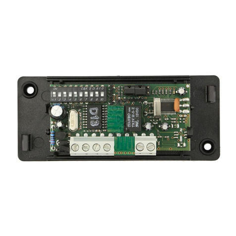
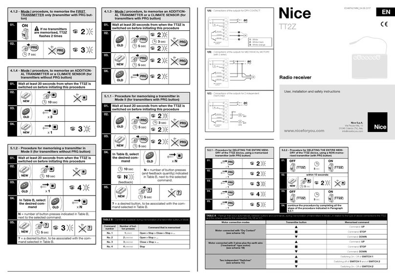
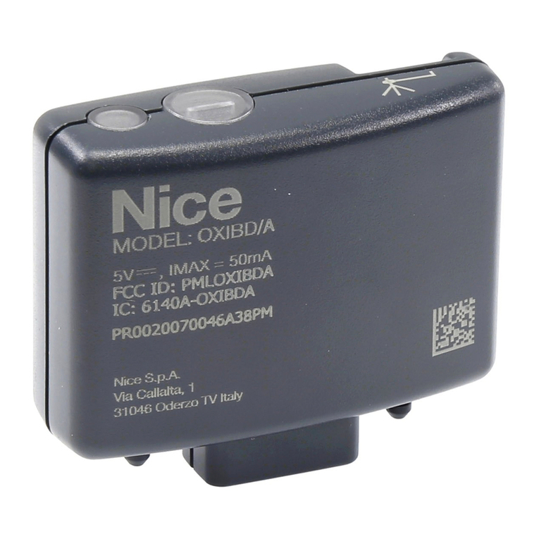
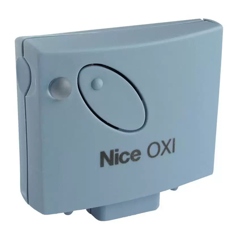
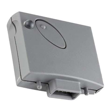
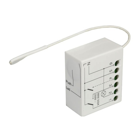
Nice NiceOne OXI/A Series Technical specifications

NiceOne
Receiver
Receiver
OXI/A family
EN - Instructions and warnings for
installation and use
FR - Instructions et avertissements
pour l’installation et l’utilisation
ES - Instrucciones y advertencias
para la instalación y el uso


1
EN
ENGLISH
1– PRODUCT DESCRIPTION AND
INTENDED USE
This receiver is part of the series “NiceOne” produced by
Nice spa. The receivers in this series are destined for use
on the control units fitted on systems for the automation of
gates, garage doors and road barriers. Any use other than
as specified herein is to be considered improper and is
strictly prohibited! The manufacturer denies all liability
for damage deriving from improper use of the product
and use other than as specified in this manual.
1.1 – The “NiceOpera” system
The receivers in the series NiceOne are part of the “NiceOp-
era” system. This system has been designed to simplify the
programming phases, use and maintenance of the devices
normally used in automation systems. The system comprises
various software and hardware devices capable of intercom-
municating via radio, by means of the “O-Code/A ” encoding
system or a “physical” connection via cable.
The main devices that make up the NiceOpera system are:
– O-Code/A compatible transmitters;
– O-Code/A compatible receivers;
– O-box programming unit;
– Control units and gearmotors with “T4 Bus”;
– O-View programmer for devices with “T4 Bus”.
2– FUNCTIONAL PRODUCT
SPECIFICATIONS
–The receiver manages “O-Code/A” radio encoding with
variable code (rolling-code), which enables use of all the
new functions in the NiceOpera system.
The receiver is also FLOR/A compatible. However, in this
case some of the exclusive NiceOpera system func-
tions described in this manual cannot be used.
–The receiver has a capacity of 1024 spaces in which to
memorise transmitters. If the transmitter is memorised in
“Mode I”, all the relative keys will occupy 1 memory alloca-
tion; otherwise if memorised in “Mode II”, each memorised
key will occupy 1 memory allocation (for memorisation pro-
cedures, see below in this manual).
–Each receiver has its own identification number called a
“Certificate”.
This number enables access to a series of operations, such
as: Memorisation of new transmitters without the need for
direct intervention on the receiver and use of the O-View
unit, by means of the “T4 Bus” connection.
The sealed coupon in the product pack contains the sheet
with the certificate number of this receiver. Caution! – this
coupon must be kept in a safe place as it enables access
to data stored in the receiver, unless further protection mea-
sures are adopted, such as the use of a security password.
–This product may only be used with control units equipped
with SM plug connectors (fig. 1). Note – to identify compat-
ible control units, refer to the Nice product catalogue.
–These models automatically recognise the characteristics of
the control unit to which they are connected and the receiv-
er self-installs as follows.
Caution! – The number and variety of the commands avail-

2
EN
1
able depend on the type and model of control unit used.
The “Table of commands” of each control unit is provided in
the instruction manual of the relative control unit.
3– PRODUCT INSTALLATION
Install the receiver by plugging it into the control unit (fig. 1).
Caution! – Before connecting or removing the receiver,
disconnect the control unit from the power supply.
The aerial supplied must also be installed, connecting it to the
specific terminals on the control unit.
Installation of an external aerial
If the aerial supplied is in an unfavourable position and the
radio signal is weak, an external aerial may be installed to
improve reception. The new aerial must be positioned as high
as possible and above any metal or reinforced concrete struc-
tures present in the area.
– Connection to the Control Unit: Use a coaxial cable with
an impedance of 75ohm. Caution! – To reduce signal dis-
persion use a cable that is as short as possible (not exceed-
ing 10 m).

3
EN
Programming warnings
The settings described in this chapter (except for pro-
cedure 6) require use of the key and led on the receiver
(fig. 2). To indicate the state of activity in progress, the
led emits a set number of flashes with a specific dura-
tion and colour (green, red or orange). For the mean-
ing of these signals, refer to Table A at the end of the
manual.
PROGRAMMING THE
MAIN FUNCTIONS
4– CAUTION! – READ THIS SECTION
BEFORE MEMORISING THE TRANS-
MITTER
The receiver can only memorise transmitters using O-Code/A
or Flo-R/A encoding.
Caution! – Before memorising a transmitter, carefully
read all memorisation procedures described below to
select the one most suited to your specific application.
5– TRANSMITTER MEMORISATION
PROCEDURE: “Mode I” AND “Mode II”
Each control unit has a set number of commands that can be
activated according to the type of receiver: The models with
“SM” connector provide 4 or 15 commands.
In general the commands can be associated with the trans-
mitter keys in two ways:
• “Mode I”. This mode enables memorisation on the receiver
of all transmitter keys or a group of the latter at once. The keys
are automatically associated with the pre-set commands of
the control unit or the receiver outputs, on models with uni-
versal connectotion.
• “Mode II”. This mode enables memorisation on the receiver
of a single transmitter key. The user can choose to which
command, of those available on the control unit, to assign the
key.
– The available commands are given in the “Commands
Table” (4 or 15 depending on the control unit), included in
the user manual for the control unit to which the receiver is
connected.
2Led Key

4
EN 5.1 – Memorisation in “MODE I”
Warning – This mode automatically assigns all com-
mands available on the receiver/control unit to the keys
on the transmitter; the installer may not change the
key/command assignments. In other words, during the
transmitter memorisation procedure, the system auto-
matically selects the commands available on the receiv-
er/control unit, and assigns them to the transmitter’s
keys. On conclusion of the procedure, each key has
been assigned to a command, according to the control
unit’s factory-set configuration.
01. Press and hold the key on the receiver until the green led
on the receiver illuminates. Then release the key.
02. (within 10 seconds) On the transmitter to be memorised,
press and hold any key until the led on the receiver emits
the first of 3 green flashes to confirm memorisation.
Note – After the three flashes, a 10-second interval is avail-
able to memorise another transmitter as required.
5.2 – Memorisation in “MODE II”
WARNINGS – This mode allows the user to manually
assign one of the available motor commands with one
of the keys of the transmitter; the installer can choose
which command and which key. In other words, during
the transmitter memorisation procedure, the installer
must assign the command (from among those available
on the control unit) to the transmitter’s key. On conclu-
sion of the procedure, to memorise another key with
another command, you must run the procedure again
from the start.
Caution! - Every automation has a list of commands
available for memorisation in Mode II; refer to the
control unit’s manual to determine which commands
are available.
01. In the control unit manual, look up the “Table of com-
mands”, select the command to assign to the transmit-
ter key and note the number corresponding to the com-
mand.
02. (on the receiver) Press the key the same number of times
as the previously noted number – the Led on the receiv-
er emits the same number of flashes repeated at regular
intervals.
03. (on the transmitter within 10 seconds) Press and hold the
selected key for memorisation until the led on the receiver
emits the first of 3 flashes (= memorisation confirmed).
Note – After the three flashes, a 10-second interval is avail-
able to memorise the same command on other keys on the
same transmitter or a new transmitter as required.
6– MEMORISING A TRANSMITTER USING
THE “ENABLE CODE” OF ANOTHER
TRANSMITTER [already memorised]
This procedure can only be used if two transmitters with
“O-Code/A” encoding are used.
Transmitters with this encoding have a secret code stored in
memory, called the ENABLE CODE.
Thanks to this code, operation of NEW transmitter can be
enabled by simply transferring the “enable code” of an OLD
transmitter (previously memorised on the receiver) onto its
memory (fig. 3). Note – For this procedure, refer to the trans-
mitter manual.
Subsequently, when the NEW transmitter is used, it will trans-
mit its own identity code to the receiver as well as the relative

5
EN
“enable code” (the first twenty times only). The receiver, after
recognising the “enable code” of an OLD transmitter (previ-
ously memorised on the receiver) automatically memorises the
identity code of the NEW transmitter sent to it.
• Preventing accidental use of this memorisation proce-
dure
To prevent memorisation on the receiver of other transmitters
not compatible with the system but with the “enable code” of
a transmitter already memorised on the receiver, this proce-
dure can be “locked” (or unlocked) by programming the func-
tion in paragraph 10.
As an alternative to locking memorisation of the entire receiver,
transfer of the “enable code” can be disabled exclusively for
some or all OLD transmitters already memorised. This opera-
tion can be performed using the O-Box programming unit.
3
7– MEMORISATION OF A TRANSMITTER
USING THE PROCEDURE IN THE
VICINITY OF THE RECEIVER
[with a transmitter already memorised]
A NEW transmitter can be memorised in the receiver memory
without acting directly on the key of the receiver, but by sim-
ply working within its reception range. To use this procedure,
an OLD transmitter, previously memorised (in “Mode I” or in
“Mode II”) and operative, is required. The procedure enables
the NEW transmitter to receive the settings of the OLD version.
WARNINGS:
• Use only one of the two procedures described below,
according to requirements.
• The procedure must be performed within the recep-
tion range of the receiver (maximum 10-20 m from
receiver).
• Repeat the same procedure for each transmitter to be
memorised.
Standard Procedure (valid for all Nice receivers)
01. On the NEW transmitter, press and hold the key…. for at
least 5 seconds (see note 1) and then release.
02. On the OLD transmitter, press key…. three times (see
note 1) and then release.
03. On the NEW transmitter, press the same key pressed in
point 01 once and then release.
Alternative Procedure (valid for this receiver only)
01. On the NEW transmitter, press and hold the key…. for at
least 3 seconds (see note 1) and then release.
02. On the OLD transmitter, press and hold the key…. for at

6
EN – (after approx. 4 seconds) the green led illuminates;
– (after approx. 4 seconds) the green led turns off;
– (after approx. 4 seconds) the green led starts flashing.
02. At this point release the key exactly......
•on the 3rd flash, to delete all transmitters, or,
•on the 5th flash, to delete the entire memory of the
receiver, including configurations.
Alternatively this function can be performed using the O-Box
or O-View programming unit.
9– DELETING A SINGLE TRANSMITTER
FROM THE RECEIVER MEMORY
A single transmitter (in your possession) memorised can be
deleted from the receiver memory as follows:
01. Press and hold the receiver key.
02. After approx. 4 seconds the green led illuminates (keep
the key pressed).
03. On the transmitter to be deleted from the memory, press
and hold any key (see note 1) until the led on the receiver
emits 5 green flashes (= deletion confirmed).
Note 1:
If the transmitter is memorised in “Mode I” any key can be
pressed.
If the transmitter is memorised in “Mode II” the entire proce-
dure must be repeated for each memorised key to be deleted.
Alternatively this function can be performed using the O-Box
or O-View programming unit.
least 3 seconds see note 1) and then release.
03. On the NEW transmitter, press the same key pressed in
point 01 for at least 3 seconds and then release.
04. On the OLD transmitter, press the same key pressed in
point 02 for at least 3 seconds and then release.
Note 1:
If the OLD transmitter is memorised in “Mode I” the NEW
transmitter will also be memorised in “Mode I”. In this case,
during the procedure press any key on either the OLD or NEW
transmitter.
If the OLD transmitter is memorised in “Mode II” the NEW
transmitter will also be memorised in “Mode II”. In this case,
during the procedure press the required command key on the
OLD transmitter and the associated key to be memorised for
this command on the NEW transmitter. This procedure must
also be repeated for each key of the NEW transmitter to be
memorised.
• Preventing accidental use of this memorisation proce-
dure
To prevent the continuous reception of a signal transmitted at
random by a transmitter not part of the system from acciden-
tally activating the memorisation procedure, this procedure
can be “locked” (or unlocked) by programming the function
in paragraph 10.
8– TOTAL RECEIVER MEMORY DELETION
All transmitters memorised can be deleted from the receiver
memory, or all data present in the latter can be deleted as
follows:
01. Press and hold the receiver key and check the following
changes in Led status:

7
EN
10 – ENABLING (or disabling)
THE RECEIVER FOR TRANSMITTER
MEMORISATION
This function enables the user to prevent memorisation of new
transmitters when the procedures “in the vicinity”(factory
setting is ON) or with “enable code” (factory setting is ON)
are used as described in this manual. To enable or disable this
function, proceed as follows:
01. Disconnect the receiver from the power supply and wait
5 seconds.
02. Power the unit up again while holding down the receiver’s
button until its led’s stop signalling and the procedure ini-
tiates; this is indicated by two short orange flashes. Then
release the key.
03. (within 5 seconds) Press the receiver key repeatedly to
select one of the following functions (Warning! – on each
press of the key the Led changes colour to indicate the
currently selected function):
•LedOFF = No lock enabled
•LedRED = Memorisation “in the vicinity” locked
•LedGREEN = Memorisation with “enable code” locked
•LedORANGE = Both memorisation modes locked (“in
the vicinity” and with “enable code”).
04. (within 5 seconds) Press any key of a transmitter already
memorised on the receiver to save the selected function.
Alternatively the lock (or unlock) function can be applied using
the O-Box or O-View programming unit.

8
EN 11 – MEMORISATION OF A TRANSMITTER
USING THE RECEIVER
“CERTIFICATE NUMBER”
[with O-Box] – This procedure can only be used if a transmit-
ter is used with “O-Code/A” encoding and when in posses-
sion of the receiver “Certificate Number”.
The “CERTIFICATE” is a personal number (factory set) identi-
fying the single receiver to distinguish it from all others.
Use of this “certificate” simplifies the procedure required to
memorise the transmitter in the receiver, as it no longer oblig-
es the installer to work within the receiver operating range.
In fact the new procedure enables transmitter memorisation
from any distance, even far from the installation site (for exam-
ple from the installer’s office – fig. 4).
WARNING – The settings described in this chapter
require use of the O-Box or O-View programming unit.
For operation of these devices, refer to the relative
instruction manuals, also available on the internet site:
www.niceforyou.com.
• The models with “SM” connector are connected to the
O-Box unit by inserting the receiver in the relative con-
nector.
OTHER FUNCTIONS
4

9
EN
Initially, the procedure consists in the installer entering, with
the aid of the programming unit “O-Box”, the required func-
tions and the relative receiver “certificate” in the memory of
the transmitter. The transmitter, ready to use, is then sent
to the client.
Subsequently, when the transmitter is used, it will transmit the
command along with the “certificate” to the receiver (the first
twenty times only). The receiver, after recognising the “certifi-
cate” as its own, automatically memorises the identity code of
the transmitter that sent the certificate.
12 – REMOTE REPLACEMENT OF A
TRANSMITTER USING “PRIORITY”
MODE
[with O-Box] – The ID code of a transmitter using O-code/A
is accompanied by a number (from 0to 3), which enables the
user to specify the transmitter’s priority level on a receiver
with respect to any other transmitters with the same code.
This “priority” serves to replace, and thus disable, use of a
transmitter that has been lost or stolen, without the need to
return to the client’s system.
Use of priority mode requires knowledge of the code of the
lost transmitter and enables maintenance of the same code
and functions of the previous transmitter.
Therefore the lost transmitter can be disabled by simply
updating the priority level of the new transmitter with the
next highest value.
On first use of the transmitter, the receiver memorises the
new priority level received and ignores any command sent
by the lost or stolen transmitter if subsequently used.
This function can be enabled (or disabled) on the receiver
(factory setting ON) and, when active, the receiver does not
update the priority level sent by the transmitter.
13 – ENABLING (or disabling)
RECEPTION OF NON-ORIGINAL
“IDENTITY CODES”
[with O-Box / O-View] – The identity codes of transmitters
with “FloR/A” and “O-Code/A” encoding can be modified as
required, using the “O-Box” or “O-View” programming unit.
The receiver can normally recognise whether a code is original
(factory set) or modified.
When this function is enabled or disabled (factory setting ON)
the receiver has the option to accept (or not) the command of
a transmitter with a modified identity code.
14 – LOCKING (or unlocking)
THE MOBILE SECTION (Rolling code)
OF THE IDENTITY CODE
[with O-Box / O-View] – This function enables the user to
lock (or unlock) management on the receiver of the variable
section (rolling code) of an identity code sent by a transmit-
ter. When the lock function is active (factory setting OFF),
the receiver treats a “rolling code” as if it were a “fixed” code,
ignoring the variable section.

10
EN 17 – CREATING THE “FAMILY GROUPS”
OF TRANSMITTERS
[with O-Box] – Each code memorised on the receiver can
be associated with one or more “family groups”, from the 4
available.
The formation of groups and their activation or deactivation
(factory setting OFF) is managed by means of the O-Box pro-
gramming unit while use of the groups, for example in a set
time-band, is managed by means of the O-View programming
unit.
18 – PROTECTION OF PROGRAMMED
FUNCTION SETTINGS
[with O-Box / O-View] – This function enables the user to
protect all programmed functions on the receiver, also disa-
bling functionality of the key and relative led. The function is
enabled by entering a password on the receiver, i.e. a maxi-
mum of 10 digits, as set by the installer.
When the function is enabled, before programming and
maintenance of the receiver, the special password must be
entered on the programming unit to unlock the receiver.
15 – MANAGING RELEASE OF THE
TRANSMITTER KEYS
(Function available only on transmitters using encoding
O-Code/A)
[with O-Box / O-View] – Normally, after sending a com-
mand, on release of the key the manoeuvre is not stopped
immediately but proceeds for a very short pre-set interval.
If necessary, the manoeuvre can be interrupted at the exact
time of key release (required for example during minimal
adjustments) by enabling this function (factory setting OFF).
16 – ENABLING (or disabling)
COMMAND DELIVERY ON THE
“T4 BUS” NETWORK
[with O- View] – On systems in which connection is via the
“T4 Bus”, if more than one receiver is installed, and there is
the need for control at a distance greater than that normally
covered by the transmitter and receiver, this function can
be enabled (on at least 2 receivers) to increase the receiver
reception range.
This enables the receiver that receives a command “via
radio” to re-transmit the command via the Bus cable to the
final receiver (in which the sending transmitter identity code is
memorised), so that this can execute the command.
To enable or disable the option to receiver and/or send radio
codes on the “T4 Bus” in a receiver (factory setting OFF), the
receivers concerned must be duly programmed, using the
O-View programming unit.

11
EN
DISPOSAL OF THE PRODUCT
This product constitutes an integral part of the automa-
tion system, therefore it must be disposed of along with it.
As in installation, also at the end of product lifetime, the disas-
sembly and scrapping operations must be performed by qua-
lified personnel.
This product is made up of different types of material, some of
which can be recycled while others must be disposed of. Seek
information on the recycling and disposal systems envisaged
by the local regulations in your area for this product category.
Caution! – some parts of the product may contain pollutant
or hazardous substances which, if disposed of into the envi-
ronment, may cause serious damage to the environment or
physical health.
As indicated by the symbol on the left,
disposal of this product in domestic
waste is strictly prohibited. Separate
the waste into categories for disposal,
according to the methods envisaged by
current legislation in your area, or return
the product to the retailer when purcha-
sing a new version.
Caution! – Local legislation may envisage serious fines in the
event of abusive disposal of this product.
OXI/A
•Decoding “O-Code/A” / “FLOR/A”
•Maximum absorption 30 mA
•Reception frequency 433.92 MHz
•Sensitivity Above 0.5 µV
•Operating temperature –20° C ÷ +55° C
•Outputs 4 (on “SM” connector)
•Dimensions and weight L. 50; H. 45; P. 19 mm;
weight 20
•Input impedance 75ohm
PRODUCT TECHNICAL SPECIFICATIONS

12
EN
As well as the functions and settings described in this
manual, the receiver offers many other features to
enhance performance, safety and ease of use.
All these settings require use of the O-Box (or in some
cases O-View) programming unit.
• Notes on Product Technical specifications
– The range of the transmitters and reception capacity of the
receivers is strongly influenced by other devices (for exam-
ple: alarms, radio headphones etc.) operating in the zone at
the same frequency. In these cases, Nice cannot guarantee
the effective capacity of its devices.
– All technical specifications stated in this section refer to an
ambient temperature of 20°C (± 5°C).
– Nice reserves the right to apply modifications to the product
at any time when deemed necessary, while maintaining the
same functionalities and intended use.
This device complies with Part 15 of the FCC Rules and with
RSS-210 of Industry Canada. Operation is subject to the fol-
lowing two conditions: (1) this device may not cause harmful
interference, and (2) this device must accept any interference
received, including interference that may cause undesired
operation. Any changes or modifications made to this device
without the express permission of the manufacturer may void
GENERAL NOTES
the user’s authority to operate this device.

13
EN
Table A
SIGNALS EMITTED BY THE
RECEIVER LED
–– Long flashes / GREEN ––
On start-up:
2Z= Transmitters with O-Code/A or Flo-R/A encoding
stored in memory
5Z= No remote control memorised
During operation:
1Z= Indicates that the code received is not stored in the
memory
1Z= During programming, indicates that the code is
already stored in the memory
3Z= Saving code in memory
5Z= Memory deleted
6Z= During programming, indicates that the code is not
authorised for memorisation
8Z= Memory full
––––––––––––––––––––––––––––––––––––––––––––––––––
–– Short flashes / GREEN ––
1Z= “Certificate” not valid for memorisation
2Z= Code cannot be memorised as is transmitting
“certificate”
3Z= During programming, indicates that the code has
been re-synchronised
4 Z= Output in “Mode II” not managed on control unit
5 Z= During deletion procedure, indicates that the code
has been deleted
5 Z= “Certificate” with higher priority that the admissible
value
6 Z= Code synchronisation failure
6 Z= Code cannot be memorised due to “incorrect key”
––––––––––––––––––––––––––––––––––––––––––––––––––
–– Long flashes / RED ––
1 Z= Non-original code block
2 Z= Code with lower priority than the authorised value
––––––––––––––––––––––––––––––––––––––––––––––––––
–– Short flashes / RED ––
1 Z= “In vicinity” programming mode block
1 Z= Memorisation by means of “certificate” block
2 Z= Memory block (PIN entry)
––––––––––––––––––––––––––––––––––––––––––––––––––
–– Long flashes / ORANGE ––
1 Z= Indicates that the code is in the memory but
outside the group currently enabled
––––––––––––––––––––––––––––––––––––––––––––––––––
–– Short flashes / ORANGE ––
2 Z= Indicates activation of block programming
(on start-up)


1
FR
FRANÇAIS
1– DESCRIPTION DU PRODUIT ET
APPLICATION
Leprésentrécepteurfaitpartiedelasérie«NiceOne»de
Nice spa. Les récepteurs de cette série sont destinés à être
utilisés sur les logiques de commande présentes dans les
installations d’automatisation de portails, portes de garage
et barrières levantes routières. Toute autre utilisation
doit être considérée comme impropre et interdite! Le
constructeur ne répond pas des dommages résultant
d’une utilisation impropre du produit, différente de ce
qui est prévu dans cette notice.
Les récepteurs de la série NiceOne font partie du système
«NiceOpera».CesystèmeaétéconçuparNiceSpApour
simplifier les phases de programmation, d’utilisation et de main-
tenance des dispositifs utilisés dans les installations d’automa-
tisation. Le système est constitué de différents dispositifs, logi-
ciels et matériels, capables de d’échanger des données et des
informations par radio à travers un système de codage appelé
«O-Code/A»ouuneliaisonfilaire«physique».
Les principaux dispositifs qui forment le système NiceOpera
sont:
– émetteurs compatibles avec O-Code/A ;
– récepteurs compatibles avec O-Code/A ;
– unité de programmation O-Box;
– logiques de commande et opérateurs avec «Bus T4»;
– programmateur O-View pour dispositifs avec «Bus
T4».
2– CARACTÉRISTIQUES FONCTION-
NELLES DU PRODUIT
• Pour tous les modèles
–Lerécepteurgèrelecodageradioappelé«O-Code/A»,
avec code variable (rolling-code), qui permet d’exploiter
toutes les nouvelles fonctions du Système NiceOpera.
Le récepteur est également compatible avec codage
FLOR/A. Dans ce cas, il ne sera toutefois pas possible d’uti-
liser certaines fonctions exclusives du système NiceOpera
décrites dans ce guide.
–Le récepteur dispose d’une mémoire avec 1024 emplace-
ments dans lesquels mémoriser les émetteurs. Si celui-ci est
mémoriséen«Mode I»,toutes ses touches occuperont
1espacedemémoire;siparcontreilestmémoriséen
«Mode II»,chaque touche mémorisée occupera 1 espace
de mémoire (pour les modes de mémorisation, voir plus loin
dans la notice).
–Chaque récepteur possède son propre numéro d’identifica-
tionappelé«Certificat».Cenuméropermetd’accéderà
denombreusesopérationscomme,parexemple:lamémo-
risation de nouveaux émetteurs sans avoir besoin d’interve-
nir directement sur le récepteur et l’emploi de l’unité O-View
enutilisantlaconnexionavec«BusT4».
Le numéro de certificat appartenant au présent récepteur
est imprimé sur le coupon scellé se trouvant dans l’embal-
lage du produit. Attention! – ce coupon doit être conser-
vé dans un endroit sûr car il permet l’accès aux données
contenues dans le récepteur à moins que des protections

2
FR
1
supplémentaires soient insérées telles qu’un Mot de passe
de sécurité.
–Ce produit peut être utilisé exclusivement avec les logiques
decommandeàconnecteurmâledetype«SM»(fig. 1).
Note - pour identifier les logiques de commande adaptées,
consulter le catalogue des produits Nice.
–Ces modèles reconnaissent automatiquement les caracté-
ristiques de la logique de commande dans laquelle ils sont
montés et le récepteur se règle automatiquement de la
façonsuivante.
Attention! – Le nombre et la variété des commandes à
disposition dépendent du type et du modèle de Logique
quel’onutilise.Le«Tableaudescommandes»dechaque
logique de commande figure dans la notice spécifique de
cette dernière.
3– INSTALLATION DU PRODUIT
Pour installer le récepteur, il faut le connecter à la logique de
commande en insérant son connecteur dans celui prévu sur
la logique (fig. 1). Attention! – Avant de connecter ou de
déconnecter le récepteur, couper l’alimentation élec-
trique de la logique de commande.
D’autre part, il faut installer aussi l’antenne fournie, en la
connectant aux bornes présentes sur la logique de com-
mande.
Installation d’une antenne extérieure
Si l’antenne fournie se trouve dans une position défavorable
et que le signal radio est faible, pour améliorer la réception il
est conseillé de remplacer celle-ci en installant une antenne
extérieure. La nouvelle antenne doit être positionnée le plus
haut possible et au-dessus d’éventuelles structures métal-
liques ou de béton armé présentes dans la zone.
– Connexion à la logique de commande: utiliser un câble
coaxial avec impédance de 75ohm. Attention! – Pour
réduire la dispersion du signal, utiliser un câble le plus court
possible (il ne doit pas dépasser 10 m).

3
FR
Recommandations pour la programmation:
Les programmations présentes dans ce chapitre (à
l’exclusion de la procédure 6) demandent l’emploi de la
touche et de la led sur le récepteur (fig. 2). Pour indiquer
l’état des activités en cours, la led émet un nombre de
clignotements donné, avec une durée spécifique et une
couleur de lumière donnée (verte, rouge ou orange).
Pour connaître la signification de ces signalisations
consulter le Tableau A, présent à la fin de cette notice.
PROGRAMMATION DES
FONCTIONS PRINCIPALES
2Led Key
4– ATTENTION ! – LIRE CE QUI SUIT
AVANT DE MÉMORISER UN
ÉMETTEUR
Le récepteur ne peut mémoriser que des émetteurs ayant un
codage O-Code/A ou Flo-R/A.
Attention! – Avant de commencer la mémorisation d’un
émetteur, lire attentivement tous les modes de mémo-
risation décrits ci-après pour évaluer lequel d’entre eux
est le plus approprié à votre cas spécifique.
5– MODES DE MÉMORISATION D’UN
ÉMETTEUR: «Mode I» et «Mode II»
Chaque logique de commande dispose d’un nombre de
commandes donné qui peuvent être activées suivant le type
derécepteur:lesmodèlesavecconnecteur embrochable
«SM»rendentdisponibles4ou15commandes;lesmodèles
avec connecteur universel rendent disponibles 2 sorties.
En général, l’association entre ces commandes et les touches
d’unémetteurpeutêtrefaitededeuxmanièresdifférentes:
• «Mode I».Ce mode permet de mémoriser dans le récep-
teur, en une seule fois, toutes les touches de l’émetteur ou un
seul groupe de touches (dans les émetteurs qui ont plusieurs
codes d’identité comme par exemple le modèle ON9). Les
touches sont associées automatiquement aux commandes
préétablies dans la logique de commande ou aux sorties du
récepteur, dans les modèles avec connecteur embrochable.
• «Mode II».Ce mode permet de mémoriser dans le récep-
teur une seule touche de l’ émetteur. L’utilisateur peut choisir

4
FR
librement à quelle commande, parmi celles disponibles sur la
logique de commande, associer la touche choisie.
– Il est possible de choisir la commande désirée parmi celles
disponiblesdansle«Tableaudescommandes »(4ou15
selon la logique), présent dans le manuel de la logique de
commande à laquelle le récepteur est connecté.
5.1 – Mémorisation en «MODE I»
Avertissement – Cette modalité attribue automatique-
ment et toutes ensemble, les différentes commandes
disponibles dans le récepteur/logique de commande,
aux touches disponibles sur l’émetteur, sans que l’ins-
tallateur puisse modifier l’association entre les com-
mandes et les touches. Autrement dit, pendant l’exé-
cution de la procédure qui mémorise l’émetteur dans
cette modalité, c’est le système qui associe automa-
tiquement les commandes disponibles dans le récep-
teur/logique, à chaque touche présente sur l’émetteur.
A la fin de la procédure, chaque touche sera associée à
une commande déterminée, selon un schéma configuré
en usine dans la logique de commande.
01. Maintenir enfoncée la touche sur le récepteur jusqu’à
ce que la led verte s’allume sur le récepteur. Relâcher
ensuite la touche.
02. (dans les 10 secondes qui suivent) Sur l’émetteur à
mémoriser, maintenir la pression sur une touche quel-
conque jusqu’à ce que la led sur le récepteur émette
le premier des 3 clignotements de couleur verte qui
signalent que la mémorisation a eu lieu.
Note – Après les trois clignotements, on dispose encore de
10 secondes pour mémoriser d’autres émetteurs.
5.2 – Mémorisation en «MODE II»
Avertissements – Cette modalité permet d’associer
manuellement une des commandes disponibles dans
le moteur à une des touches de l’émetteur, permettant
ainsi à l’installateur de choisir la commande et la tou-
che désirée. Autrement dit, pendant l’exécution de la
procédure qui mémorise l’émetteur dans cette moda-
lité, c’est l’installateur qui associe la commande désirée
(parmi celles disponibles sur la logique de commande),
à la touche de l’émetteur. A la fin de la procédure, pour
mémoriser une autre touche avec une autre comman-
de, il faudra répéter la procédure depuis le début.
Attention ! - Chaque automatisme a sa propre liste
de commandes mémorisables en Mode II ; il faut
donc consulter le manuel de la logique de commande
pour choisir la commande à associer à la touche de
l’émetteur.
01. Chercherdanslemanueldelalogiquele«Tableaudes
commandes»disponibles;choisirlacommandequel’on
désire attribuer à la touche de l’émetteur puis noter le
numéro qui correspond à la commande.
02. (sur le récepteur) Presser la touche un nombre de fois
identique au nombre noté ci–dessus – la led du récepteur
émet le même nombre de clignotements répétés.
03. (sur l’émetteur, dans les 10 secondes qui suivent) Main-
tenir la pression sur la touche choisie pour la mémorisa-
tion jusqu’à ce que la led du récepteur émette le premier
des 3 clignotements (= mémorisation effectuée).
Note – Après les trois clignotements, on dispose encore
de 10 secondes pour mémoriser la même commande sur
d’autres touches du même émetteur ou d’un nouvel émetteur.
Table of contents
Languages:
Other Nice Receiver manuals

Nice
Nice RB02 User manual

Nice
Nice OXIBD User manual

Nice
Nice NiceOne OX4 Product manual

Nice
Nice OXILR User manual

Nice
Nice FLOX2R Installation manual

Nice
Nice OXIBD User manual

Nice
Nice HSTT2L User manual

Nice
Nice elero Revio-868 SW User manual

Nice
Nice OXILR Technical specifications

Nice
Nice RMF3004 User manual

Nice
Nice FLOR Technical specifications

Nice
Nice HSRE12 User manual

Nice
Nice elero Revio-868 SW User manual

Nice
Nice FLO Series User manual

Nice
Nice OXI Technical specifications

Nice
Nice TT2N Technical specifications

Nice
Nice TT2Z K Operating instructions

Nice
Nice tt2d User manual

Nice
Nice Apollo FLOR FLOXR Series Technical specifications

Nice
Nice FLOXMR Service manual