Nicherons FXO User manual

!
!
!
SpoTel: SpoATA series FXO/FXS Voice Gateway
User Manual

!
!
!
Table of Contents
1.!Equipment Introduction!.....................................................................................!1!
1.1 Overview!.......................................................................................................!1!
1.2 Equipment appearance (back view)!.........................................................!1!
1.3 Power supply!................................................................................................!2!
1.4Network Applications!....................................................................................!2!
1.5 Functions and Features!..............................................................................!3!
1.5.1Protocol standard supported!............................................................!3!
1.5.2 Voice and Fax parameters!..............................................................!3!
1.5.3 Supplementary service!....................................................................!3!
2.!Basic Operations!.................................................................................................!4!
2.1 Phone Call!.....................................................................................................!4!
2.1.1 Phone or Extension Number!...........................................................!4!
2.1.2 Direct IP Calls (SPOATA-8S FXS gateway)!...................................!4!
2.2 Call Features!.................................................................................................!5!
2.3 Sending and Receiving Fax!........................................................................!6!
2.3.1 SpoATA-8S supports four fax modes:!...........................................!6!
2.3.2 T. 38 and Pass-Through!..................................................................!6!
3.!Local IVR Operation!............................................................................................!7!
3.1 Inquire IP address!.......................................................................................!7!
3.2 Factory Reset!...............................................................................................!7!
3.3 Configure LAN Port’s IP Address!...............................................................!7!
4.!WEB Configuration (all SpoATA series)!...........................................................!8!
4.1 WEB Login!....................................................................................................!8!
4.1.1 Login!..................................................................................................!8!
4.1.2 Login WEB!.........................................................................................!9!
4.2 Configuration menu!...................................................................................!10!
4.3 Status and Statistics!..................................................................................!11!
4.3.1 System Information!.......................................................................!11!
4.3.2 Registration Information!...............................................................!12!
4.3.3 TCP/UDP Statistics!.........................................................................!12!
4.3.4 RTP Session Statistics!....................................................................!12!
4.4 Quick Setup Wizard!...................................................................................!13!
4.5 Network Configuration!..............................................................................!13!
4.5.1 Local Network!.................................................................................!13!
4.5.2 VLAN Parameter!.............................................................................!14!
4.5.3 ARP!...................................................................................................!16!
4.6 SIP Server!...................................................................................................!16!
4.7 Port Configuration!.....................................................................................!18!
4.8 Advanced!....................................................................................................!20!
4.8.1 FXO parameters!..............................................................................!20!

!
!
!
4.8.2 Media Parameter!............................................................................!22!
4.8.3 SIP Parameter!.................................................................................!24!
4.8.5 Digit Map!.........................................................................................!28!
4.8.6 Feature Codec!.................................................................................!29!
4.8.7 System Parameter!..........................................................................!31!
4.9 Call & Routing!............................................................................................!33!
4.9.1 Port Group!.......................................................................................!33!
4.9.2 IP Trunk!...........................................................................................!35!
4.9.3 Routing Configuration!....................................................................!35!
4.9.4 IP-Tel Routing!.................................................................................!36!
4.9.5 Tel-IP/Tel Routing!..........................................................................!37!
4.10 Manipulation Configuration!....................................................................!38!
4.10.1 IP-Tel Caller!..................................................................................!38!
4.10.2 Tel-IP Caller!..................................................................................!39!
4.10.3 Tel-IP Caller!..................................................................................!40!
4.11 Maintenance!.............................................................................................!40!
4.11.1 syslog Parameter!..........................................................................!40!
4.11.2 Firmware Upload!..........................................................................!41!
4.11.3 Data Backup!..................................................................................!41!
4.11.4 Data Restore!.................................................................................!42!
4.11.5 Ping Test!.......................................................................................!42!
4.11.6 Tracert Test!..................................................................................!43!
4.11.7 Password Modification!.................................................................!44!
4.11.8 Factory Reset!................................................................................!44!
4.11.9 Device Restart!..............................................................................!45!
5.!Glossary!..............................................................................................................!45!
6.!Configuration Examples!...................................................................................!46!

! ! ! SpoTel!Series!Voice!Gateway:>!User!Manual!
1!
!
1. Equipment Introduction
1.1 Overview
SpoATA FXO or FXS analog phone adapter (ATA)/gateway provides low cost, simple
operation VoIP solutions for enterprise, the family office (SOHO), remote office and branch
enterprise. ATA connects to analog telephone, fax and traditional analog PBX with
standard voice interfaces and provided high quality voice service. SPOSpoATA series VoIP
access gateway adopts standard SIP protocol and is compatible with leading IP PBX (such
as Asterisk, 3CS), soft-switch and SIP-based platform. SPOSpoATA series analog gateway
includes following model:
!SpoATA-8S (with 8x FXS ports)
!SpoATA-8O (with 8x FXO ports)
!SpoATA-4O (with 8x FXO ports)
This manual is using SptATA-8O as an example, introducing the function of devices and
parameter configuration.
1.2 Equipment appearance (back view)

! ! ! SpoTel!Series!Voice!Gateway:>!User!Manual!
2!
!
1.3 Power supply
SPOATA-4/8O is desktop equipment and powered by an 12DC power adapter which works
between AC 110-240 V
Power adapter specs:
Input: 100-240V, 50-60Hz
Output: 12VDC
1.4Network Applications
!
Figure 4-1:Network Applications

! ! ! SpoTel!Series!Voice!Gateway:>!User!Manual!
3!
!
1.5 Functions and Features
1.5.1Protocol standard supported
• SIP V2.0 (RFC 3261,3262,3264)
• SDP (RFC 2327)
• REFER (RFC 3515)
• RTP/RTCP (RFC 1889,1890)
• STUN (RFC 3489)
• ARP/RARP (RFC 826/903)
• SNTP (RFC 2030)
• DHCP/PPPoE
• TFTP/HTTP/HTTPS
• DNS/DNS SRV (RFC 1706/RFC 2782)
• VLAN 802.1P/802.1Q
• Diff Server
1.5.2 Voice and Fax parameters
• G.711A/U law, G.723.1, G.729AB
• Comfortable Noise Generation (CNG)
• Voice Activity Detection (VAD)
• Echo Cancellation (G.168)
• Adaptive Dynamic Jitter Buffer
• Voice and fax gain control
• Hook flash
• Modem
• T.38/Pass-through
• DTMF Mode: Signal/RFC2833/INBAND
1.5.3 Supplementary service
• Busy tone detection
• No current take out stitches detection
• Voice interrupted detection
• One stage dialing
• Two stage dialing
• PSTN exterior ports polling
• Polarity Reversal
• FAS(Fake billing correction )
• DC/AC impedance config
• Calls detection (Bellcore Type 1&2, ETSI,DTMF)

! ! ! SpoTel!Series!Voice!Gateway:>!User!Manual!
4!
!
• Voice mail
• Direct IP Call
• IP Trunk
2. Basic Operations
2.1 Phone Call
2.1.1 Phone or Extension Number
1)FXO Call Out
• One stage dialing: After receiving dialing number from softswitch/IPPBX, the
number will be called out via FXO ports that is configured under “Port select”.
• Two stage dialing: the call arrives the gateway from SIP connection: the caller
will hear 2nd dial tone and could then dial outside number.
2)Dial the number directly and press #.
• Dial outside number with FXO: when the message “please dial the extension
number” or second dial tone is played, enter the dialing number. The gateway
will then send the number to SIP server/connection, such as soft switch or
IPPBX.
• Off-hook auto-dial: (calling via FXO): the gateway will automatically connect to
the preset extension or ring group number according to the default hotline
number.
2.1.2 Direct IP Calls (SPOATA-8S FXS gateway)
SpoATA-8S allows direct call through IP address. A point-to-point call could be dialed
without registration.
Elements necessary to configure a direct IP call:
1) Both SpoATA-8S or other ATA, are on public IP addresses;
2) Both SpoATA-8S and other ATA are on the same LAN on private IP addresses;
3) Both SpoATA-8S and other ATA could be connected through a router using public or

! ! ! SpoTel!Series!Voice!Gateway:>!User!Manual!
5!
!
private IP addresses (with necessary port forwarding or DMZ).
Operation Process
1)Pick up the analog phone then dial “ *47 ”
2)Enter the target IP address.
【Note】:No dial tone will be played between step 1 and step 2
Examples:
If the target IP address is 192.168.0.160, the dialing convention is *47, then
192*168*0*160. Followed by pressing the “#” key or waiting another 3 seconds, the
remote unit will ring.
【Note】:Th direct IP calls could not be made from one port to another port within the
same gateway since both ports are using the same IP. Only the standard SIP port 5060
could be used in the direct ip dialing.
2.2 Call Features
SpoATA-8S supports all traditional and advanced phone functions.
Table 2.2-1 Feature Codec
Feature Codec
Operation Instructions
*158#
Inquire the LAN port IP address
*159#
Inquire the WAN port IP address
*114#
Inquire port account
*150*
Set how IP address would be obtained
*157*
Set network mode
*152*
Set IP address
*153*
Set Subnet mask
*156*
Set default gateway IP address
*193#
Obtain IP address through DHCP
*160*1#
Open WAN port to access web
*166*000000#
Factory reset

! ! ! SpoTel!Series!Voice!Gateway:>!User!Manual!
6!
!
*111#
Restart device
*#
Call hold
*47*
IP address call
*51#
Enable call waiting
*50#
Disable call waiting
*87*
Blind transfer
*72*
Enable Unconditional Call Forward
*73#
Disable Unconditional Call Forward
*90*
Enable Busy Call Forward
*91#
Disable Busy Call Forward
*92*
Enable No Answer Call Forward
*93#
Disable No Answer Call Forward
*78#
Enable DND
*79#
Disable DND
*200#
Access Voice mail
Flash/Hook
Switch between incoming calls, If not in session, flash/hook will switch a
new channel for new call.
2.3 Sending and Receiving Fax
2.3.1 SpoATA-8S supports four fax modes:
1)T.38(FoIP)
2)Pass-Through
3)Modem
4)adaptive
2.3.2 T. 38 and Pass-Through
T.38 is the preferred method because it is more reliable and works well in most network

! ! ! SpoTel!Series!Voice!Gateway:>!User!Manual!
7!
!
conditions. If the service provider supports T.38, please use this method by selecting T.38
as fax mode (default). If the service provider does not support T.38, pass-through mode
could be used. If there is problem sending or receiving Fax, toggle the Fax Tone Detection
Mode setting.
3. Local IVR Operation
3.1 Inquire IP address
After attaching an to a FXS ports, feature code could be dialed to inspect the current ip
status.
: dialing *158# to inquire LAN IP address
: dialing *159# to inquire WAN IP address.
3.2 Factory Reset
Dial *166*000000#, then hang up. The gateway will then reboot.
3.3 Configure LAN Port’s IP Address
Before configuration, please ensure:(1)The device is power on; (2)device is connected
to the network;(3)Telephone is attached to FXS port.
1) Configure dynamic IP address by DHCP:
Off-hook; Dial “*150*2#”; On-hook/hang up;
After 10 seconds, the device will reboot.
2) Configure Static IP address
Off-hook; Dial “*150*1#”; On-hook;
Then configure IP and mask as follow:
• Configure IP address:
Off-hook; input “*152*172*16*0*100# ”; On-hook
• Configure subnet mask:

! ! ! SpoTel!Series!Voice!Gateway:>!User!Manual!
8!
!
Off-hook; input “*153*255*255*0*0# ”; on-hook
• Configure gateway IP address
Off-hook; input “*156*172*16*0*1# ”; on-hook.
3) Query the IP address of device: Off-hook, input“*158#”
4) If the SpoATA-8S is on PPPoE to get IP address,it should be configured by web
browser.
【Note】:The telephone will play voice prompt “Setting successfully” if the setup is correct
4. WEB Configuration (all SpoATA series)
4.1 WEB Login
First to connect the Device to network properly, refer to chapter 3 “Operation”. Off-hook
and dial*158# to inquire its IP address.
4.1.1 Login
The LAN port default IP address is 192.168.11.1, WAN port will obtain IP address by DHCP.
First modify your pbx to the same IP segment/domain, with Windows 7 as an example, the
computer IP could be set as 192.168.11.10:

! ! ! SpoTel!Series!Voice!Gateway:>!User!Manual!
9!
!
Figure 4.1-1Modify IP address
Check connection between computer and device, click “Start”-> “run”-> input “cmd”, run
“ ping 192.168.11.10 –t “ to verify the connectivity between them.
4.1.2 Login WEB
Open web browser, then enter IP address The login interface will appear.
Figure 4.1-1 Login Interface
Default username and password: admin/admin, click “OK” to enter into web
management interface.

! ! ! SpoTel!Series!Voice!Gateway:>!User!Manual!
10!
!
Figure 4.1-2 Configuration Interface
4.2 Configuration menu
SpoATA web management interface displays in the left. Navigate the menu to complete the
configuration.
Figure 4.2-1 Navigation Tree
When LAN port is set at bridge mode, the several sub-menus will not display, including
"Routing configuration”, "DHCP service", "DMZ host", "forward rules" and "static routing"
and "ARP" etc.
! ! ! SpoTel!Series!Voice!Gateway:>!User!Manual!
11!
!
4.3 Status and Statistics
4.3.1 System Information
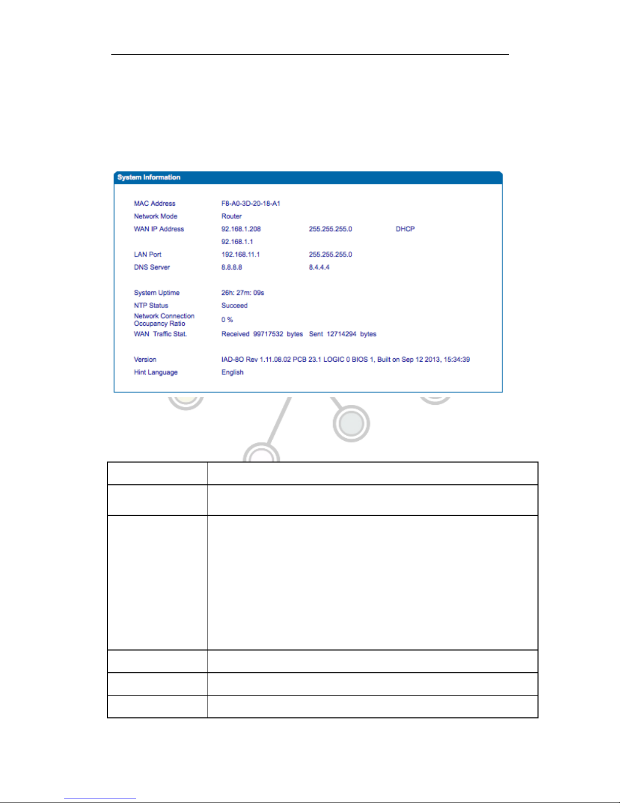
System information interface shows the run information as following figure 4.3.1 below:
Figure 4.3-1 System Information
System information as follow:
Table 4.3-1 System Information Description
MAC address
WAN port hardware address. The device ID in HEX format.
Network Mode
Display network mode, include bridge and rout. If it is bridge, WAN port display
Network, and the WAN port IP as same as the LAN port IP.
WAN Port
Shows WAN IP address of ATA ,
DHCP mode: all the field values for the Static IP mode are not used (even though they
are still saved in the Flash memory.) The ATA acquires its IP address from the first
DHCP server it discovers from the LAN it is connected.
Using the PPPoE feature: set the PPPoE account settings. The ATA will establish a
PPPoE session if any of the PPPoE fields is set.
Static IP mode: configure the IP address, Subnet Mask, Default Router IP address,
DNS Server 1 (primary), DNS Server 2 (secondary) fields. These fields are set to zero
by default.
LAN Port
Shows LAN IP address. If network Mode is bridge, LAN port won’t display.
DNS Server
Display DNS server IP address and default gateway information
System Uptime
Time elapsed from device power on to now.

! ! ! SpoTel!Series!Voice!Gateway:>!User!Manual!
12!
!
Network Traffic Statics
Total bytes of message received and sent by network port.
Version
Includes: product mode, software version, hardware version and built time etc.
4.3.2 Registration Information
Figure 4.3-2 Port and Port group registration information
4.3.3 TCP/UDP Statistics
Figure 4.3-3 TCP/UDP Statistics Information
Figure 4.3-3 shows TCP sending and receiving, UDP sending and receiving packets of
statistical information since the device launched.
4.3.4 RTP Session Statistics
Figure 4.3-4 RTP Session Statistics
Figure 4.3-4 display real-time RTP conversation flow data information, including:
Port, voice codec, packet period, local port, peer IP, peer port, sent packets, receive
packets, lost packets, jitter and duration.

! ! ! SpoTel!Series!Voice!Gateway:>!User!Manual!
13!
!
4.4 Quick Setup Wizard
Quick configuration wizard will guide users to configure the device step by step. Users only
need to configure network, SIP server and sip port during the setup. Basically, after these three
steps, users are able to make voice call through the gateway.
4.5 Network Configuration
4.5.1 Local Network
There are two modes, namely, route and bridge. When the gateway is set as route mode,
the gateway will work as small router and NAT function is enabled. In this setup, WAN
port normally connect to uplink router/switch or ADSL MODEM, while LAN port connects
local computer or other network device (such as Ethernet switches, Hubs etc). When
bridge mode is set, WAN and LAN ports are daisy chained together as in Ethernet switch.
In bridge mode, only WAN IP address and DNS should be configured. In route mode,
default LAN IP is 192.168.11.1 but could be changed by users.
Network configure interface as below:
Figure 4.5-1 Local network

! ! ! SpoTel!Series!Voice!Gateway:>!User!Manual!
14!
!
• “Link Speed & Duplex” used to select Ethernet mode, include 5 selections between,
“Auto Detect” (default)、“10Mbps half-duplex”、“10Mbps full-duplex”,
“100Mbpshalf-duplex”, “100Mbps full-duplex”.
• When select“ obtain IP address automatically”, ATA will obtain IP address by DHCP.
• When select “Use the following IP address”, fixed IP address will be set manually.
• When select “PPPoE”, please fill in account and password from your .
【Notes】:
1)If DHCP is slected, please verify that working DHCP server is in network.
2)After the network configuration, restart device configuration validation.
4.5.2 VLAN Parameter
Quality! of! service! is! particularly! important! for! the! transport! of! traffic! with! special!
requirements.!In!particular,!much!technology!has!been!developed!to!allow!computer!
networks!to!become!as!useful!as!telephone!networks!for!audio!conversations,!as!well!
as!supporting!new!applications!with!even!stricter!service!demands.
1) 802.1Q
The IEEE 802.1Q standards define architecture , services , protocols and algorithms for
Virtual Bridged LANs.
No Quality of Service mechanisms are defined in this standard, but an important
requirement for providing QoS in this standard, e.g. ability to regenerate user priority of
received frames using priority information contained in the frame and the User Priority
Regeneration Table for the reception Port.
2) 802.1p
IEEE 802.1p standards, Traffic class expediting and dynamic multicast filtering:
It describes important methods for providing QoS at MAC level. IEEE 802.1p is very
effective. Packets will be sent according to the priority level. IEEE 802.1p describes no

! ! ! SpoTel!Series!Voice!Gateway:>!User!Manual!
15!
!
admission control protocols. It would be possible to give Network Control priority to all
packets and the network would be easily congested.
There are three VLAN: data VLAN, voice LAN and management VLAN. VLAN configuration
interface as following figure 4.5-3:
Figure 4.5-3 VLAN parameter configurations
Table 4.5-1VLAN parameter configurations
Data VLAN
Data 802.1Q VLAN ID(0-4095)
Fill out an ID to describe a data VLAN group, ID 0
used to management VLAN, can’t used to service
configure.
Data 802.1p Priority(0-7)
802.1 protocol to control network traffic priority,
Priority from 0-7.
Voice VALN
Voice 802.1Q VLAN ID(0-4095)
Fill out an ID to describe a voice VLAN group, ID 0
used to management VLAN, can’t used to service

! ! ! SpoTel!Series!Voice!Gateway:>!User!Manual!
16!
!
configure.
Voice 802.1p Priority(0-7)
802.1 protocol to control network traffic priority,
Priority from 0-7.
Voice VLAN use following
separate IP interface
Can use dynamic or static IP address
Voice VLAN DNS Server
Can use dynamic or static DNS server address
Management
VLAN
Management 802.1Q VLAN
ID(0-4095)
Fill out an ID to describe a data VLAN group, ID 0
used to management VLAN, can’t used to service
configure.
Management 802.1p Priority
(0-7)
802.1 protocol to control network traffic priority,
Priority from 0-7.
Management VLAN use
following separate IP interface
Can use dynamic or static IP address
Management VLAN DNS server
Can use dynamic or static DNS server address
【Note】: Restart the device to apply changes
4.5.3 ARP
ARP brief introduction:
ARP is address resolution protocol. After configuring ARP, users can get physical address
through device IP address. Under TCP/IP network environment, each host is assigned a
32-bit IP address. ARP is a tool that converts IP address into MAC address.
ARP configuration interface as follows:
Figure 4.5-4 ARP Parameters
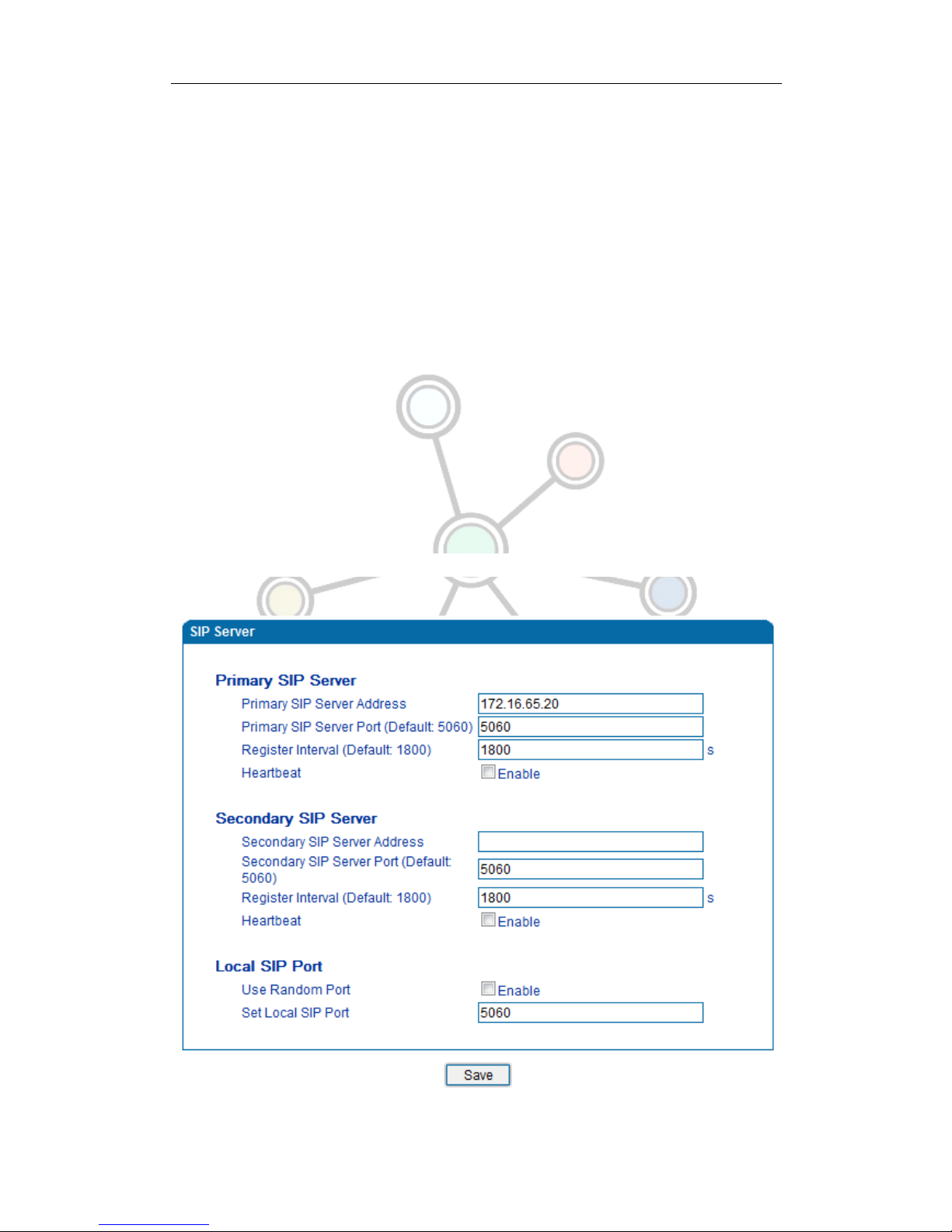
4.6 SIP Server
SIP server introduction:
! ! ! SpoTel!Series!Voice!Gateway:>!User!Manual!
17!
!
1)SIP server is the main component of VoIP network and responsible for establishing
all the SIP phone calls. SIP server also called SIP proxy server or registered server.
IPPBX and the soft-switch can act as SIP server.
2)Usually, SIP server does not participate in the media process.
In SIP network, the media always using end-to-end to hand the consultation. In some
particular situation or business processing such as “Music On Old”, SIP server will
actively participate in the media negotiation. Simple SIP server is responsible only for
establishment, maintenance and cleaning conversation, don't interfere in call. While
relatively complex SIP server also called SIP PBX. It does not only provide the basic
call connection and basic conversational support, but also offer plenty of business
features such as: Presence, Find-me, Music On Hold.
3)SIP server based on Linux platform, such as: SpoTel, OpenSER、sipXecx,VoS,Mera etc.
4)SIP server based on windows platform, such as :miniSipServer、Brekeke,VoIPswitch etc.
5)Carrier grade soft-switch platform, such as Cisco, Huawei, Zteetc.
SIP server configuration interface as follows:
Figure 4.6-1 SIP Server Configuration Interface
This manual suits for next models
3
Table of contents
Other Nicherons Gateway manuals


